Get in touch with Suzhou Simitch Machinery Co., Ltd Company

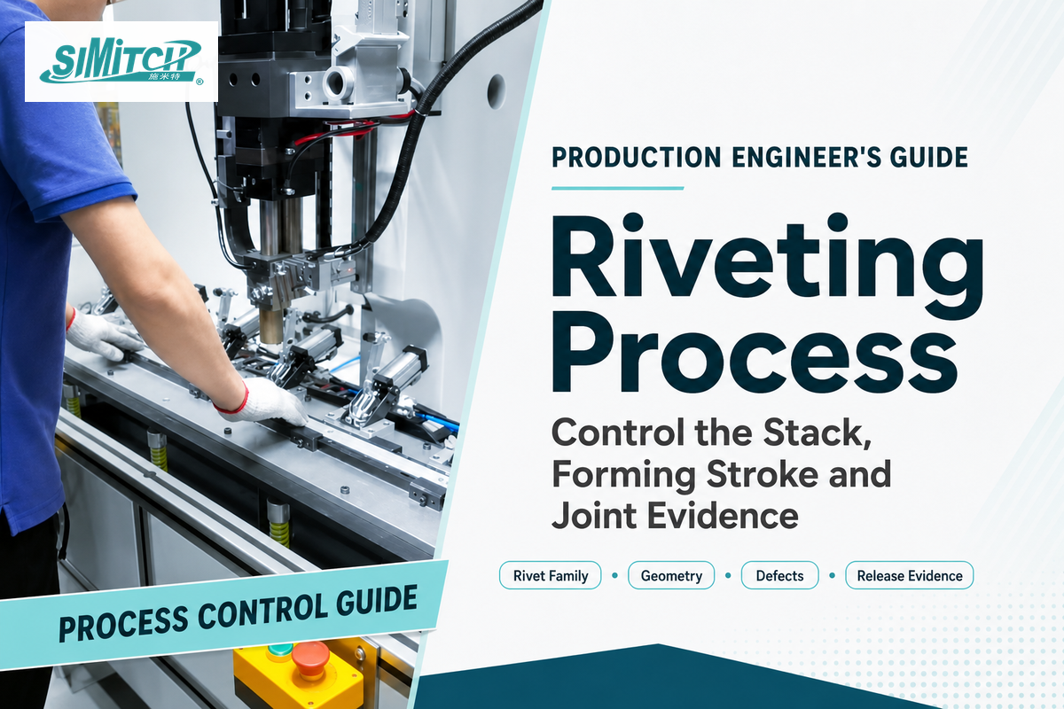
The riveting process is a permanent mechanical joining method that joins two or more parts by placing a rivet through or into the material stack and deforming part of its shank. Once installed, the rivet creates a second head or mechanical interlock that clamps the stack. Joint quality depends on the rivet, hole, access, material pairing, tooling, and verified process window.
This guide starts with five control stages used to organize the analysis, then moves into the choices that matter on a production line: rivet family, forming motion, hole geometry, material pairing, defect diagnosis, monitoring limits, qualification, and the information an equipment supplier needs.
Updated September 2026 · By XCX
Quick process map
| Input | Material stack, access, joint loads, environment, production rate, and inspection plan |
| Geometry | Rivet diameter and length, grip range, hole, edge distance, pitch, head and die |
| Setting | Aligned support plus controlled axial force, impact, orbital motion, or a self-piercing stroke |
| In-process evidence | Tool position, force-displacement signature, recipe, fastener presence, and result code |
| Acceptance | Dimensional checks, sectioning or nondestructive inspection, and destructive tests selected for the joint |
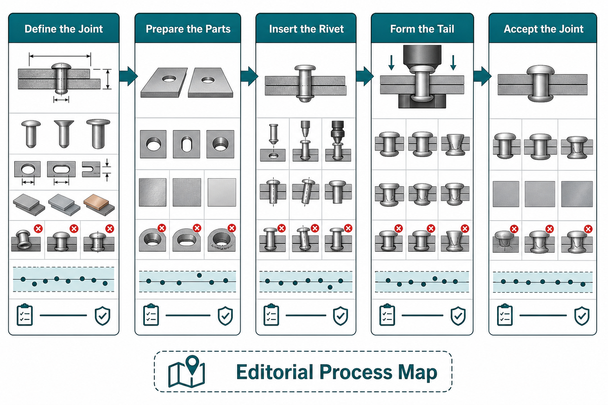
This guide organizes riveting into five control stages: define the joint, prepare the parts, insert or feed the correct rivet, deform the tail or create the interlock, and inspect the result. These stages are an editorial process map, not a standardized industry step count. Production control must cover the prepared stack as well as the setting stroke; a good force curve cannot repair a bad hole or wrong die.
What the Riveting Process Actually Is
The riveting process forms a permanent mechanical joint by deforming a rivet after it reaches the intended position in a material stack. The factory head forms the head on one end, while the tail end of the rivet becomes a shop head, flare, bulb, or interlock on the other side.
In practical terms, riveting is a mechanical assembly process; the research institute TWI describes it as generally permanent even though a rivet can be drilled out. That distinction matters: removal is possible, but removal usually destroys the fastener and may alter the hole. A riveted joint is therefore not a reusable bolted joint, and the exact mechanism changes with the rivet family and rivet material.
- Define the joint — record the materials, stack thickness, access, load direction, environment, appearance, rate, and inspection requirement.
- Prepare the parts — make and verify any required holes, remove harmful burrs, align the stack, and close unintended gaps.
- Insert the rivet — confirm family, material, diameter, length or grip range, head style, orientation, and die match.
- Form the tail — apply the specified axial force, impact, orbital motion, mandrel pull, or self-piercing stroke while supporting the joint.
- Accept the joint — inspect formed geometry and process evidence, then perform the joint tests required by the release plan.
How does riveting work?
During setting, the riveting tool pushes, squeezes, hammers, rotates, or pulls the rivet so material flows into a retained shape. Inserting a rivet is only the start: to install the rivet, place the rivet through the aligned hole or at the defined self-piercing point, then deform the rivet without damaging the rivet shank.
With a blind fastener, the rivet body—the deformable body of the rivet—forms a rear bulb as the mandrel is pulled; solid rivets form a shop head, while self-piercing rivets flare into the lower sheet against a die. TWI reports tail expansion of about 1.5 times the original stem diameter as a general description, but that is not a universal acceptance number; the drawing, fastener specification, and joint qualification control the finished geometry. A useful definition distinguishes the head of the rivet from the tail of the rivet, and a release requirement must name the applicable limits before a station can install rivets repeatedly.
Rivet Types: What Each Family Needs From the Joint
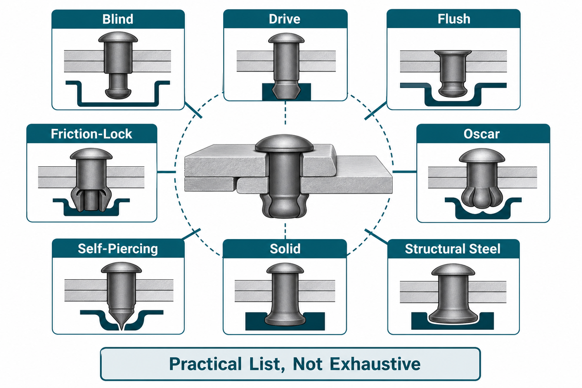
Rivet selection starts with classification axes, not a memorized family count. Ask whether the riveting method requires access to both sides, whether a prepared hole is allowed, how the tail can form, what head can remain, and which materials must touch. Different types of rivets can belong to several descriptive groups at once, so no fixed count is canonical.
TWI lists eight widely used types—blind, drive, flush, friction-lock, Oscar, self-piercing, solid, and structural steel rivets—as its practical taxonomy. These main types are one cited teaching list, not every rivet form in service; a pop rivet is a common blind-rivet name. The reference table below stays within that taxonomy and its cited formation descriptions; it is not a cross-process selection framework.
Keep fastener and equipment labels separate
A rivet set is the tool face that shapes a rivet head; a pneumatic rivet gun and hydraulic riveting equipment describe driving systems, not rivet families. Split rivets, countersunk rivets, structural blind rivets, and a hollow rivet describe different fastener forms, each of which must be matched to the materials to be joined and its own acceptance evidence.
A pneumatic rivet system may be hand-guided, while automated riveting can bind feed, position, force, inspection, and traceability into the assembly process. The selected method still needs representative trials; an equipment label alone does not qualify a joint for aerospace applications or any other industry.
| Rivet type | Cited access or form | Cited formation description | Scope note |
|---|---|---|---|
| Solid | Factory-head and shop-head sides | EAA describes bucking or squeezing the tail into a shop head | Use the applicable fastener and installation procedure |
| Blind | Installed from one side | TWI describes a tool pulling the mandrel so the body expands on the blind side | Published grip and hole limits remain family-specific |
| Drive rivet | TWI classifies it as a blind rivet | A short mandrel is hammered in so the inserted end flares | Verify retention against the substrate and specification |
| Flush rivet | Countersunk head and hole | The installed head finishes at the external surface | TWI identifies appearance and aerodynamic drag as the purpose |
| Friction-lock rivet | Early blind-rivet form; countersunk or domed | TWI describes it as resembling an expanding bolt | Application acceptance still comes from its own specification |
| Oscar rivet | Blind-rivet form with a split hollow shaft | The splits bend and flare as the mandrel is drawn | TWI says the wider surface reduces pull-out risk |
| Self-piercing | No prepared hole | It pierces the top sheet without fully piercing the lower sheet | Stack, die, rivet and force still require joint-specific trials |
| Structural steel | Historically used to join structural steel | TWI notes that high-strength bolts have largely replaced this use | Follow the controlling project code and procedure |
One TWI self-piercing-riveting study shows how quickly a family label becomes a specific process: its example fixes aluminium 6016, a 5 mm rivet diameter, 5 mm rivet length, a DZ 9-0.25 die, and 5 mm edge distance. Those values describe that study matrix, not a universal self-piercing-riveting recipe.
Rivet nuts sit at the boundary of this taxonomy. They install from one side but create a reusable internal thread for a separate bolt or screw, so the final joint is not completed by the rivet nut alone. Treat one as a threaded insert when defining assembly sequence and service access.
Self-piercing riveting deserves a similar scope boundary. It is a cold-forming route with a semi-tubular rivet, punch, and supporting die. Readers comparing that equipment family can continue to self-piercing riveting machines; this article keeps its focus on process control.
Hot Riveting, Cold Riveting, and the Tool Motion That Forms the Tail
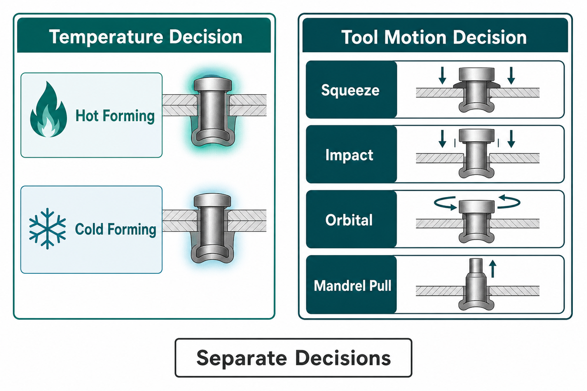
Hot versus cold riveting is a material-formability decision, while squeezing, impact, orbital motion, and mandrel pulling describe how the forming load reaches the rivet. These axes are related but not interchangeable. A viable route must form the head without cracking the rivet, damaging the stack, or exceeding the required cycle.
EAA calculations give about 345 lbf to set a 3/32-inch solid rivet and 615 lbf, about 2.7 kN, for a 1/8-inch rivet. Its description separates continuous axial force from a squeezer and repeated axial impacts from a rivet gun. Either route fails when the load is not aligned with the shank.
The Pacific Northwest National Laboratory publication on AZ31 magnesium riveting shows why temperature cannot be reduced to “large equals hot.” Its abstract describes magnesium as 33% lighter than aluminium and 75% lighter than steel, then reports brittle head fracture at room temperature, extra cycle time from preheating, and a rotating-hammer process that formed a head in 0.23 seconds while refining grains from about 15 to 2.6 µm.
Production equipment operates on a different scale from hand setting. The Simitch servo-riveting page states an 80 kN capacity, 200 mm effective stroke, 0–333 mm/s speed range, ±2% pressure accuracy, and 0.01 mm repeat positioning for its named system. These are first-party specifications for that system, not a joint recipe or proof that maximum force is preferred.
Once trials show that controlled position and force are required, evaluate the joint, feed, fixture, die, inspection, and traceability interfaces of servo-controlled riveting assembly systems. Equipment selection begins after the stack and acceptance plan are defined.
Hole, Grip, Edge Distance, and Pitch
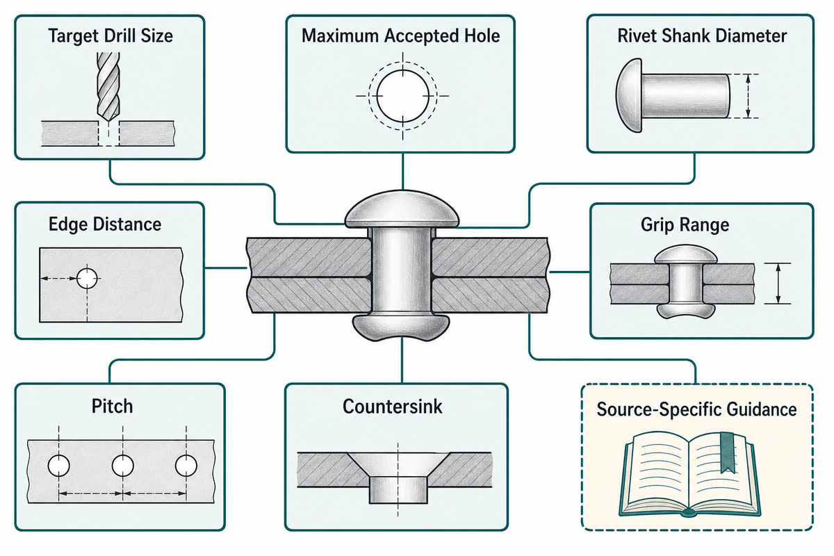
Hole and grip geometry control how the rivet fills, clamps, and transfers load. Specify the target drill separately from the maximum accepted hole, then match rivet diameter and grip to the actual stack. Edge distance and pitch must follow the governing fastener and joint design, because one universal multiple cannot represent every material or rivet family.
Published supplier guidance shows why a drawing note must name its source and process. Atlas Copco’s solid-rivet sizing guide describes a drill about 0.003 inch larger than the rivet. Orbitform’s solid-rivet design guide describes a rivet diameter 0.010 to 0.015 inch smaller than the hole and ties protrusion to forming motion. These are source-specific design guides, not a universal tolerance stack or a substitute for the current fastener specification.
| Published guide | Quantified statement | Context retained here | Release requirement |
|---|---|---|---|
| Atlas Copco | Drill about 0.003 in (0.076 mm) larger than the rivet; formed head above 1.4D across and about 0.3D high | General solid-rivet sizing guidance | Bind the actual hole and head range to the drawing |
| Orbitform | Rivet 0.010–0.015 in (0.254 mm to 0.381 mm) smaller than the hole; stick-out about 50% to 60% of diameter for orbital forming and about 100% for impact | Solid-rivet design with motion-specific protrusion | Validate hole, protrusion, motion and finished head together |
| ASSEMBLY Magazine, quoting BalTec and Alcoa Fastening Systems engineers | For a 0.25 in (6.350 mm) break-stem example: nonstructural hole 0.261–0.272 in (6.629 mm to 6.909 mm); structural hole 0.257–0.261 in (6.528 mm to 6.629 mm) | Break-stem examples, not solid buck-rivet limits | Keep structural and nonstructural fastener data separate |
| TWI research example | Aluminium 6016, 5 mm diameter, 5 mm length, DZ 9-0.25 die and 5 mm edge distance | One self-piercing-riveting test matrix | Do not transfer its values to another stack without trials |
Numbers That Do Not Decide Joint Quality Alone
Separate supplier guides give a roughly 0.003-inch drill allowance and a 0.010–0.015-inch rivet-to-hole difference; neither is a universal acceptance clearance for a 1/8-inch rivet. Blind-rivet holes may differ again because the body and mandrel system behave differently. Reject a datasheet comparison that merges source-specific guidance into one tolerance stack.
Grip range is the fastener’s permitted stack-thickness interval, not simply body length. Measure the compressed stack, including coatings and gaps that will remain after clamping. Edge distance is measured from hole center to the sheet edge, pitch is center-to-center spacing, and a countersink needs its own angle and depth; all interact with material, thickness, load direction, and failure mode.
Material Pairing and Galvanic Risk
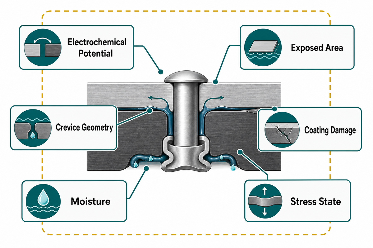
Material pairing must consider electrochemical potential, exposed area, crevice geometry, coating damage, moisture, and the joint’s stress state. Once hole and grip geometry are controlled, a galvanic series can show which metal tends to act as anode or cathode in a stated environment, but potential difference alone does not rank the damage that a real rivet-and-sheet geometry will produce.
University of Delaware corrosion notes place aluminium near −0.8 V and 300-series stainless steel near −0.07 V, a gap of about 0.73 V. Their rivet example changes the outcome without changing that gap: a small aluminium rivet in a large stainless plate is a small anode coupled to a large cathode and can be attacked severely.
Area ratio is still not the whole model. University of Kentucky’s record for Matzdorf and co-authors reports worse nearby coating attack around 316 stainless fasteners than around more noble titanium fasteners in the tested system. Available cathodic current, coatings, electrolyte, and geometry can reverse a simple nobility ranking.
The multi-institutional 2021 study with General Motors co-authors reports less coupled-region corrosion in self-piercing riveted joints than in spot-welded joints because the smaller crevice sustained a higher local pH. Galvanic corrosion still occurred in both. Riveting changed the crevice; it did not remove the mechanism.
Material pairing is one part of the broader sheet-metal fastening decision. For a focused treatment of mixed-metal stacks, see the aluminium joining guide.
What Goes Wrong: Defect Modes in a Riveted Joint
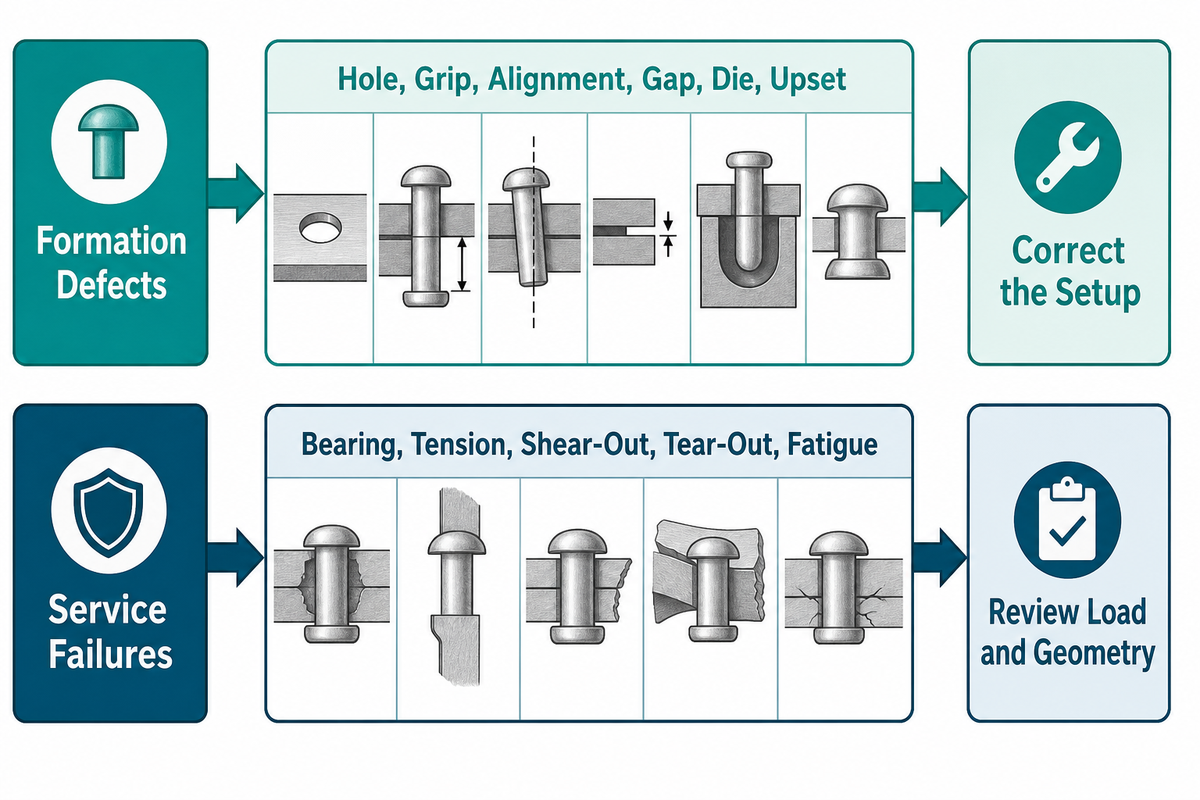
Riveting failures belong to two different lifecycle stages. After material compatibility is bounded, formation defects can still occur during installation: wrong hole, grip, alignment, gap, die, or upset. Load-induced failures appear after a sound joint carries service loads. Mixing the stages misdirects corrective action.
Use the 2-Stage Formation–Service Failure Split
The 2-Stage Formation–Service Failure Split is an editorial diagnostic, not a standard: first decide whether the defect was created during setting or emerged under service load, then choose the inspection and corrective action. A “bad rivet” result is only a symptom label, not a diagnosis. This keeps a malformed head from being confused with a qualified joint that later failed by bearing, shear-out, or fatigue.
Formation defects
| Observed condition | Likely process cause | Check before resetting | Corrective direction |
|---|---|---|---|
| Bent or dumped solid rivet | Excess protrusion or non-axial load | Rivet length, alignment, support | Restore axial load and correct protrusion |
| Gap remains between sheets | Parts not closed before upset | Clamp sequence and stack seating | Close the stack before forming |
| High mandrel break | Grip below minimum, material too soft, or hole variation | Stack thickness and hole map | Match grip and stabilize the hole |
| Mandrel pull-through | Rivet too short, oversized or tapered hole, burr, or sheet gap | Body length, grip, roundness, burr and seating | Correct geometry before changing pull force |
| Cracked shop head | Rivet condition, excess deformation, or poor room-temperature formability | Material state, time window and finished head | Use the specified condition and forming route |
| Unexpected stroke or curve | Wrong die, rivet, stack, seating, or tool condition | Part identity, die height, fastener feed and fixture | Correct the physical mismatch before tuning the band |
For solid riveting, the EAA guide uses 1.5D protrusion before setting and a finished shop head around 1.5D across and at least 0.5D deep as its shop guidance. It also contrasts 36,000 psi AD rivets with softer 16,000 psi A-category rivets and describes a 2 sec to 3 sec driving window for AD material. Those figures belong to that aircraft solid-rivet context and do not transfer to every blind or self-piercing fastener.
Load-induced failure modes
Bearing, net tension, shear-out, tear-out, cleavage, rivet shear, and fatigue cracking describe how a loaded joint may fail. ASTM D5961’s B, C, L, S, and T codes are specifically bearing-response codes for fastened polymer-matrix composite laminate coupons. They are useful vocabulary inside that scope, not a generic metal-rivet defect checklist.
One 2024 carbon/epoxy bolted-coupon study illustrates the geometry interaction: changing edge-distance-to-diameter ratio within the same material system shifted failure from shear-out toward progressive bearing. The lesson is bounded but practical—geometry can change the mode even when material stays fixed; it does not make material or load direction irrelevant.
What In-Process Monitoring Can and Cannot Tell You
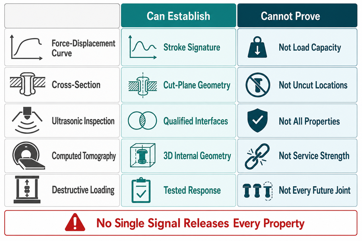
A force-displacement curve is a process indicator, not direct proof of joint load capacity. It can reveal changes in force, position, stroke sequence, stack response, or tool behavior, but interior interlock, remaining sheet thickness, cracks, and destructive strength need other evidence. Acceptance should combine signals instead of asking one trace to certify every property.
| Evidence level | What it can establish | What remains unseen or unproved |
|---|---|---|
| Force-displacement curve | Stroke signature against a validated process envelope | Direct interior geometry and load capacity |
| Cross-section | Interlock, undercut, remaining thickness and local deformation on the cut plane | Uncut locations and service-load distribution |
| Ultrasonic inspection | Selected internal interfaces or discontinuities after method validation | Properties outside the technique’s qualified sensitivity |
| Computed tomography | Three-dimensional internal geometry within resolution limits | Production-rate practicality and direct service strength |
| Destructive loading | Measured response and failure mode for the tested specimen and condition | Every future joint unless sampling and process control support the inference |
ISO 12996:2013 specifies tensile-shear testing for single mechanical joints in one-layer and multilayer specimens up to a single sheet thickness of 4.5 mm. Its purpose is to determine mechanical characteristics and failure modes. The standard’s destructive route makes the boundary clear: an in-process trace and a joint-strength result are different evidence.
The 2021 self-piercing-riveting review reports Mucha’s 2014 steel-joint study, in which raising force from 14 to 32 kN increased strength by 36%. The same review warns that higher force can raise residual stress and die wear. Force is a real lever with a real cost, and it is the wrong lever when the fault is a wrong die or bad stack.
Ford Global Technologies LLC patent US20200094310A1 illustrates a pre-stroke die-height check: the system uses a low-force contact position to infer installed die height before authorizing the operation. The example shows that the pre-stroke check and the final setting curve establish different facts. The client guide on force-displacement curve validation explores the adjacent monitoring layer.
When Riveting Test Results Point to Another Joining Route
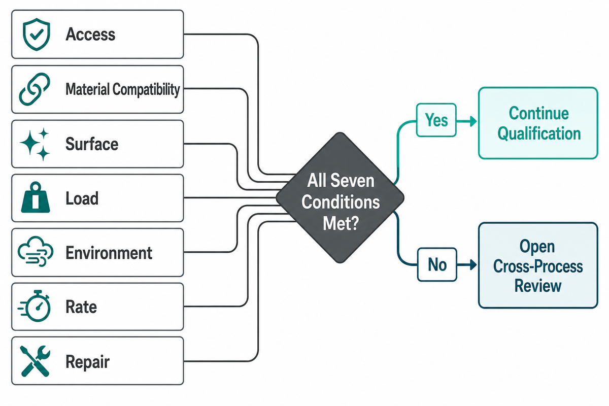
A riveting trial should trigger a broader route review when the chosen rivet family cannot meet access, material compatibility, surface, load, environment, rate, or repair requirements inside a defensible process window. That is a stop condition for this process, not a verdict that one alternative is universally superior.
Is riveting stronger than welding?
Not as a universal rule. Published monotonic comparisons disagree because material, sheet thickness, geometry, load direction, and process setup change the result. The introduction to a study of aluminium 6111 self-piercing-riveted joints, summarising earlier work rather than reporting its own measurement, states that fatigue strength at 10⁶ cycles was about twice that of spot-welded joints. Treat that figure as directional evidence from a secondary summary, not a universal design value.
Mechanism matters more than a winner label. Interfacial slip can relax stress concentration around a weld nugget, and cold forming can add local work hardening where welding adds heat. Corrosion behavior adds a third axis. This article stops at the conditions that invalidate the selected riveting process; use the metal joining methods framework for actual cross-process selection.
Qualifying the Process: Standards Scope and Guarding
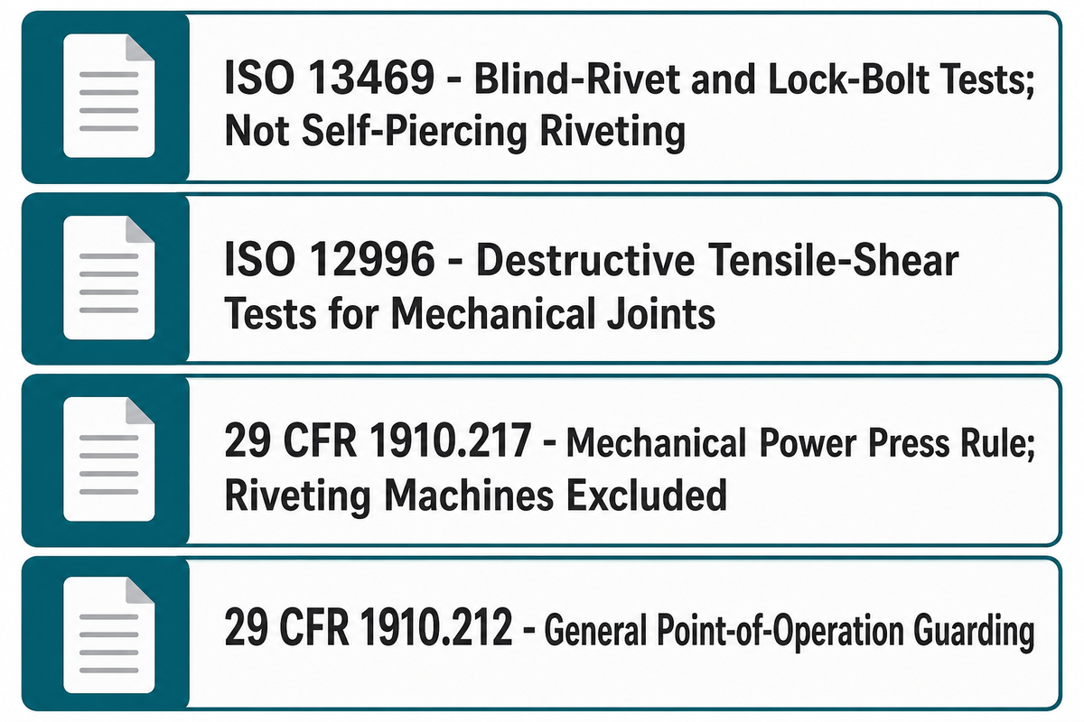
Qualification begins by matching each standard to the joint and test it actually covers. Those process limits then determine which dimensional, blind-rivet, destructive mechanical-joint, installation, and machine-guarding documents apply. A familiar document number provides no protection when its specimen, process, material, or jurisdiction differs from the production case.
ISO 13469:2014 covers test procedures for interference-fit and form-fit blind-rivet joints and lock-bolt joints; it does not cover self-piercing riveting. ISO 12996 covers destructive tensile-shear testing for mechanical joints. The ISO catalogue for rivets records dimensional standards from 1999–2002 at stage 90.93, meaning reviewed and confirmed—not proof of why they remain unchanged.
United States scope has a second trap. 29 CFR 1910.217(a)(5) excludes riveting machines from that section’s mechanical-power-press requirements. It does not exclude them from 29 CFR 1910.212, which requires point-of-operation guarding where machine operation exposes an employee to injury.
“The point of operation of machines whose operation exposes an employee to injury, shall be guarded.”
Section 1910.212 does not name riveting machines in its illustrative list, so the accurate statement is based on the general duty, not a fabricated named-machine clause. Rivet making is different again: 1910.218(i)(2) points rivet manufacturing to forging-machine provisions. A concise machine-guarding review should follow the application risk assessment.
The Rivet Process Release Record: What to Freeze Before Production
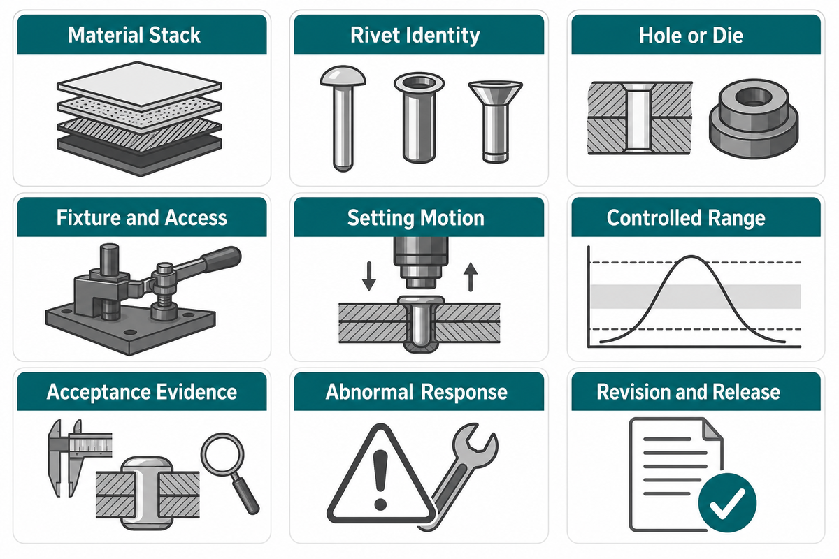
A Rivet Process Release Record binds one selected joint stack, rivet, hole or die, setting motion, controlled variables, inspection method, and abnormal response to one revision. It is a release document for a qualified riveting route, not a supplier-selection scorecard or a comparison among joining technologies.
Complete One Record for One Qualified Route
| Record field | What must be fixed | Evidence to attach | Change-control trigger |
|---|---|---|---|
| Material stack | Material, coating, thickness range and order | Released drawings and material records | Any material, coating or order change |
| Rivet identity | Family, designation, material, head and grip | Fastener specification and lot trace | Supplier, designation or lot rule change |
| Hole or die | Hole range or die identification and condition | Capability study or verified die record | Tool repair, replacement or geometry drift |
| Fixture and access | Clamp sequence, support and tool orientation | Fixture drawing and access trial | Part or station layout change |
| Setting motion | Squeeze, impact, orbital, pull or defined servo profile | Released recipe and tool identification | Machine, actuator or motion change |
| Controlled range | Approved force, position, time and sequence limits | Representative trial and challenge parts | Limit, software or sensor change |
| Acceptance evidence | Geometry, signal and destructive or nondestructive checks | Qualified sample, method and threshold | Inspection method or sampling change |
| Abnormal response | Stop, contain, rework, reject and restart logic | Injected-fault acceptance record | New fault mode or response change |
| Revision and release | Part, process, software and inspection revisions | Named approvals and effective date | Any upstream revision change |
This record is the process-data attachment that should travel with a tooling or equipment discussion. Machine buying questions remain outside this article; the riveting equipment guide and riveting equipment category own that selection intent.
Process data attachment
Attach the released material and part drawings, selected rivet specification, representative qualified sample, approved setting trace, inspection method, and abnormal-response plan. These records describe the chosen process; they do not rank suppliers.
Key takeaway
Reliable riveting controls the stack before the stroke, the rivet and tool during the stroke, and the joint evidence after the stroke. Force traces, sectioned joints, and destructive tests answer different acceptance questions; no single green signal releases every property.
Bring the joint, not just the rivet number
Simitch develops intelligent joining equipment and system-level solutions for automotive components, energy-storage batteries, solar photovoltaic products, home appliances, and HVAC terminals. Share the stack, geometry, acceptance test, rate, and failure response with Simitch’s joining-equipment services team to start a bounded application review.
Frequently Asked Questions
What is the riveting process?
The riveting process inserts a selected rivet into or through a material stack and permanently deforms it to create a retained head or mechanical interlock.
This guide’s process map uses five control stages: define the joint, prepare and align the parts, insert the correct rivet, form it with the specified motion and support, then inspect the geometry and evidence required by the release plan. Different rivet families use different holes, access, tools, and acceptance limits. Each released recipe should bind those inputs to one part revision.
What is riveting used for?
Riveting is used to make permanent mechanical joints where access, mixed materials, coating sensitivity, heat input, appearance, rate, or service behavior favors a fastener-based route.
Applications include sheet-metal assemblies, transport structures, appliances, HVAC products, enclosures, and many other components. Suitability cannot be inferred from the industry label alone. The actual material stack, loads, environment, geometry, production method, and inspection plan determine whether a solid, blind, self-piercing, or alternative joint is viable. Qualification must use representative materials and the intended process window.
Why is riveting no longer used?
Riveting is still widely used, but welding, adhesive bonding, clinching, threaded fasteners, and integrated forming have replaced it in some joints where added mass, holes, noise, access, or fastener cost is unfavorable.
The shift is application-specific rather than universal. Riveting remains attractive for selected dissimilar materials, cold joining, one-sided access with blind fasteners, and processes that need a mechanical fastener. A route should be tested against the actual stack and lifecycle requirements instead of chosen from a claim that one method has replaced another everywhere.
What are the disadvantages of using rivets?
Rivets add fastener mass and supply cost, may require holes or two-sided tooling, can mark coatings, create noise, and are difficult to remove without destroying the fastener.
Poor hole or grip control can also produce a loose or malformed joint. These limits do not make riveting inferior; they are inputs to a route comparison.
How are rivets measured?
Rivets are measured by body diameter and a family-specific length or grip designation, with head style, material, mandrel or stem, and installation-hole range added as needed.
For a solid rivet, length relates to the stack plus the protrusion needed to form the shop head. For a blind rivet, choose a published grip range that contains the compressed stack thickness; body length is not a direct substitute. The prepared hole has both a target and an accepted range. Countersunk heads also require a defined included angle, depth, and finished surface condition. Record the full fastener designation and drawing revision instead of ordering from diameter alone.
What can I use instead of rivets?
Alternatives include resistance spot welding, laser welding, clinching, threaded fasteners, lock bolts, adhesive bonding, flow-drill screws, and formed tabs, but each route needs its own qualification.
Compare them on material compatibility, access, heat, surface effect, disassembly, rate, tooling, inspection, joint loads, and environment. A viable substitute must be proven on the same stack and requirement set.
How this analysis was built
The analysis separates process evidence from equipment claims and traces its dimensional, corrosion, testing, and guarding statements to standards, public research, regulations, and named practitioner material. Simitch’s company scope and the 80 kN named-system figure are identified as first-party information, not universal performance evidence.
References & Sources
- TWI — What Is a Rivet and How Do They Work?
- Atlas Copco — How to Select the Correct Rivet Size
- Orbitform — Design Guidelines for Solid Rivets
- Experimental Aircraft Association — Setting or Driving Solid Rivets
- Pacific Northwest National Laboratory — Friction-Based Riveting of AZ31 Magnesium
- University of Delaware — Galvanic Corrosion and Area Ratio
- Penn State — Corrosion of Spot-Welded and Self-Piercing-Riveted Joints
- Chinese Journal of Mechanical Engineering — Review of Self-Piercing Riveting
- International Journal of Adhesion and Adhesives — Fatigue of Self-Piercing-Riveted Aluminium 6111 Joints
- ISO 12996:2013 — Destructive Testing of Mechanical Joints
- ISO 13469:2014 — Blind-Rivet and Lock-Bolt Joint Testing
- eCFR — 29 CFR 1910.212 General Requirements for All Machines
- eCFR — 29 CFR 1910.217 Mechanical Power Presses