Get in touch with Suzhou Simitch Machinery Co., Ltd Company

Updated August 2026 · Written by XCX
Sheet metal fastening is the use of hardware or formed features to join thin metal parts. Sound selection connects service access, assembly geometry, the exact sheet stack, production controls, and finished-joint proof before anyone commits to hardware or equipment.
Key takeaway
Sheet metal fastening should be selected by screening seven method families against four records: Access, Stack, Service, and Proof. Catalog strength narrows a component choice; representative specimens and an agreed test plan qualify the assembled joint.
Quick specification card
7 method families
Threaded, riveted, captive, and formed
Threaded, riveted, captive, and formed
4 pre-screen inputs
Access, Stack, Service, Proof
Access, Stack, Service, Proof
3 evidence layers
Component, process, finished joint
Component, process, finished joint
1 controlled revision
Drawing, sample, criteria, and owner aligned
Drawing, sample, criteria, and owner aligned
Sheet Metal Fastening at a Glance: What Changes the Choice?
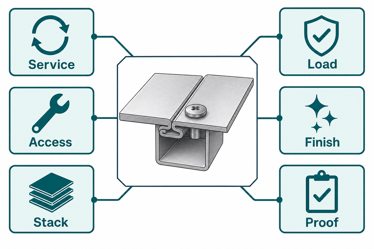
Sheet metal fastening covers added hardware and formed interlocks used to hold thin metal parts together. Before comparing screws, rivets, or joining equipment, define whether the joint must reopen, which sides tools can reach, what each layer is, how the assembly is loaded, and what evidence will count as acceptance.
1. Service
Planned removal, replaceable unit, reuse, tamper control.
Planned removal, replaceable unit, reuse, tamper control.
2. Access
Head side, reaction side, tool approach, inspection path.
Head side, reaction side, tool approach, inspection path.
3. Stack
Grade, temper, thickness, order, coating, environment.
Grade, temper, thickness, order, coating, environment.
4. Load
Shear, peel, tension, vibration, cyclic spectrum, stiffness.
Shear, peel, tension, vibration, cyclic spectrum, stiffness.
5. Finish
Visible head, underside button, distortion, coating repair.
Visible head, underside button, distortion, coating repair.
6. Proof
Specimen, process window, sampling, test direction, limit.
Specimen, process window, sampling, test direction, limit.
Drawings that omit these decisions are not quotation-ready. If welding and adhesive bonding also remain candidates, compare the wider family of metal joining methods before narrowing the mechanical routes.
Common mistake: requesting unit prices while the assembly sequence and acceptance test are still open. Low component cost cannot rescue a route that needs inaccessible tooling or an unplanned secondary operation.
Seven Sheet Metal Fastening Methods Compared
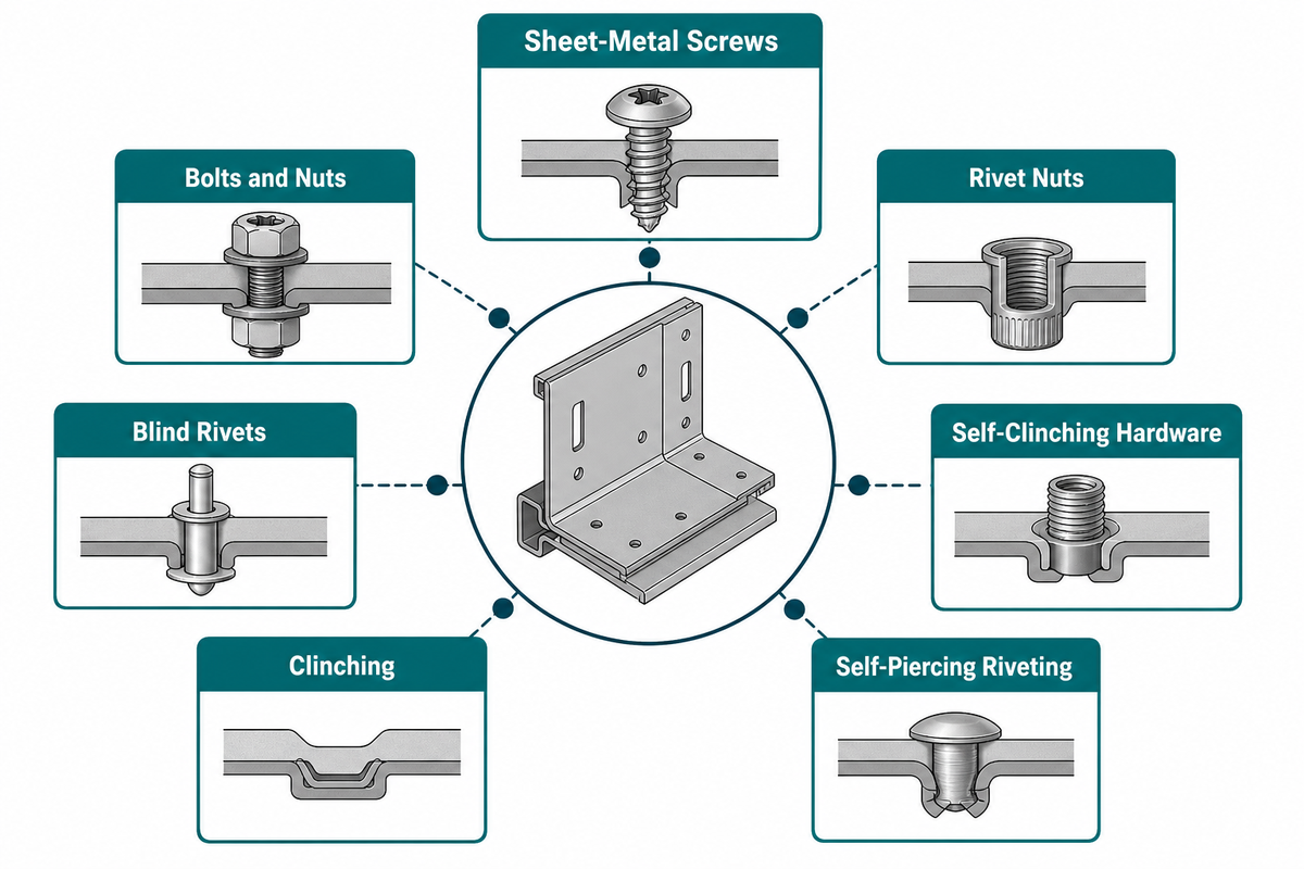
Seven practical sheet metal fastening families cover most production shortlists: sheet-metal screws, bolts and nuts, rivet nuts, blind rivets, self-clinching hardware, clinching, and self-piercing riveting. The table expands two families into common subtypes so buyers can see where installation, service, and proof obligations change.
How do you fasten sheet metal?
Start with the function, then remove infeasible routes. Threaded hardware usually fits planned service; blind fasteners help where the completed assembly blocks the far side; clinching and self-piercing riveting suit permanent formed joints when the stack and two-sided tooling path are qualified. Every route still needs hole, edge, coating, and load checks.
| Fastener type / variant | Typical fit | Installation access | Service | Limitations / not suitable for |
|---|---|---|---|---|
| Self-tapping screw | Direct thread formation in prepared sheet | Driver side; support may still matter | Removable, with finite reuse | Unverified strip torque or weak local sheet |
| Self-drilling screw | Hole-making and fastening in one operation | Driver side plus chip/exit clearance | Removable | Sensitive finish or uncontrolled drilling debris |
| Bolt and nut | Serviceable clamp joint with separate nut | Both sides during assembly | Highly serviceable | Closed cavities without captive reaction |
| Rivet nut / threaded insert | Reusable thread added to thin sheet | Blind-side setting system | Mating screw removable | Unqualified spin-out, pull-out, or hole variation |
| Blind rivet | Permanent lap joint with one working side | One setting side; blind bulb needs space | Destructive removal | No cavity for bulb or retained mandrel risk |
| Self-clinching nut or stud | Captive thread in a prepared hole | Press plus reaction support at installation | Mating hardware removable | Sheet hardness, thickness, or edge geometry outside the qualified window |
| Clinching | Fastener-free permanent interlock | Punch and die sides | Destructive separation | Stack lacks formability or finish cannot accept the formed button |
| SPR, same-material stack | Permanent riveted interlock without a pre-hole | Setter/punch and die sides | Destructive removal | Rivet, die, and stack have no proven process window |
| SPR, mixed-material stack | Permanent joining where fusion routes are difficult | Setter/punch and die sides | Destructive removal | Stack order, corrosion, ductility, or load path is unresolved |
Terminology that changes the specification
In sheet metal fabrication, fastening sheet metal starts by naming the type of sheet metal material and the finished sheet metal surface. Common sheet metal parts include thin sheet metal covers, sheet metal panels, a formed metal panel, and other thin metal sheets; use cases range from automotive housings to consumer electronics.
| Term family | Details to state | Why it matters |
|---|---|---|
| Sheet metal screws | Self-tapping or self-drilling screws; hex or Phillips recess; countersink; pre-drilling | The head, shank or pilot, and driver access define the installation methods. |
| Self-drilling detail | A drill-shaped pilot of the fastener | The screw makes a hole in sheet metal using its own point, so exit clearance and debris control matter. |
| Threaded fasteners | Steel fasteners, bolt/nut sets, reusable joint plan | Thread engagement and torque belong to the actual host sheet and load case. |
| Rivet nuts and rivet bushes | Knurled body, rivet nut tool, hole, grip, push-out, torque-out | They create reusable threads in thin metal, but spin and pull-out still need proof. |
| Self-clinching fastener | Clinching ring, host-sheet hardness, hole, edge, press support | During pressing, metal flows into retention features through controlled cold flow. |
| Unthreaded rivets | Pop rivets, mandrel condition, blind-side cavity | The type of fastener changes removal, retained-part, and inspection planning. |
| Weld fasteners | Weld process, projection geometry, coating repair | They are outside this mechanical shortlist and need a separate thermal joining review. |
| Captive anchor features | Stud, nut, recess, sheet condition | High strength hardware cannot compensate for weak local sheet or a poor hole. |
| Selection language | Fastener types, sheet material, service, access, and proof | The right fastener comes from the right fastening record, not a generic label. |
Fasteners are designed for particular installation conditions, and fasteners are used safely only inside the verified conditions. Treat values recommended by the fastener manufacturer as component inputs; sheet metal fastening solutions and other solutions for sheet metal assemblies still require buyer-owned joint proof.
Procurement should compare process routes only after engineering fixes the required function. Price alone cannot make a rivet and a threaded insert interchangeable when one joint must reopen and the other may be drilled out.
Removable or Permanent? Define Service Needs Early
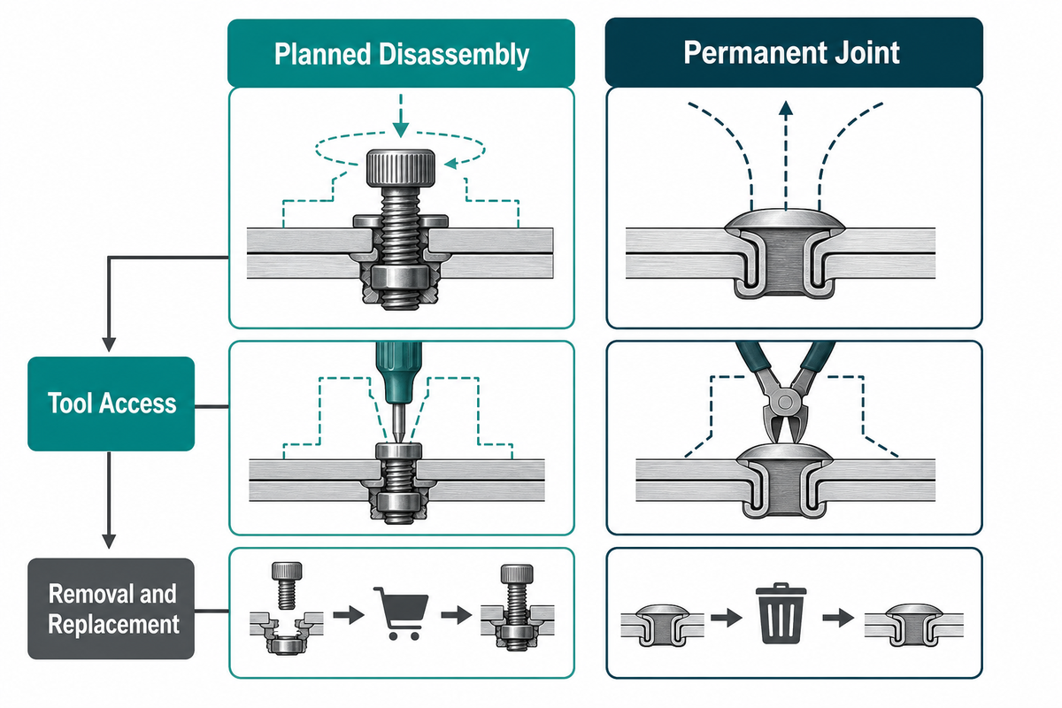
Serviceability and physical access are early gates, but neither one is universally first. Record the replacement unit, expected opening method, tool reach after final assembly, reuse expectation, and tamper need before treating a threaded route as removable or a formed route as permanently inaccessible.
Planned disassembly
- Start with bolts, screws, rivet nuts, or captive threaded hardware.
- Check thread durability and locking strategy.
- Confirm tool access after final assembly.
- Define coating condition after repeated service.
Permanent joint
- Screen blind rivets, clinching, or SPR.
- Define destructive removal and repair.
- Set the scrap and containment boundary.
- Record how rejected joints will be handled.
The 2025 NIST review places disassembly inside product design and the whole product life cycle, while a peer-reviewed joining review treats disassembly capability as one comparison dimension rather than a universal first rule. The practical objection is maintenance ownership: if no team owns removal and replacement, “serviceable” remains a label rather than a controlled requirement.
Boundary: permanence belongs to the qualified joint system. Even a removable screw becomes functionally permanent when the tool cannot reach it, while a nominally permanent joint may have a documented drilling or panel-replacement procedure.
One-Side vs Two-Side Access Changes the Fastening Route
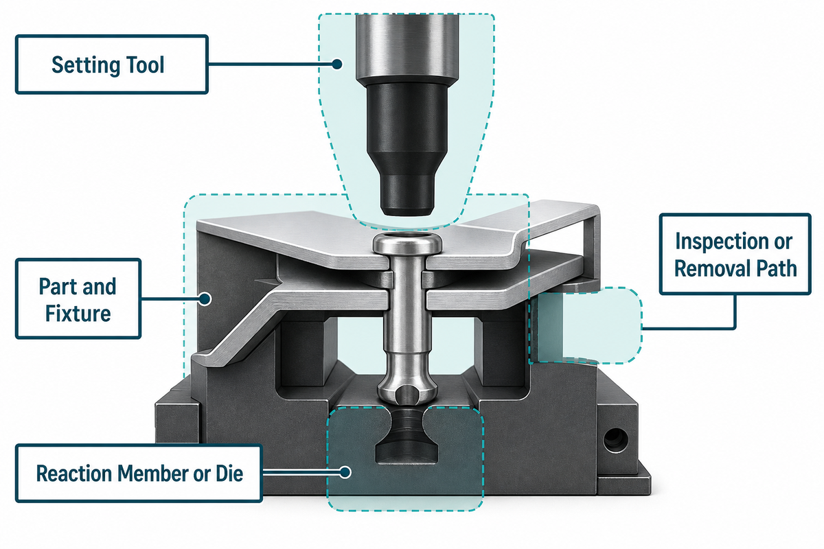
Access means more than seeing the fastener head. Viability requires space for the setting tool, any reaction member or die, the part and fixture during assembly, the operator or automation envelope, and the planned inspection or removal path after surrounding components are installed.
Access-to-proof decision path
- Mark the visible head or driver approach.
- Mark the punch, anvil, die, nut, or reaction path.
- Overlay fixture, throat depth, flange width, and production sequence.
- Overlay guarding, operator reach, and hazardous-energy controls.
- Reserve inspection, sectioning, removal, and repair access.
TWI describes SPR as a semi-tubular rivet driven by a punch and die; the rivet pierces the upper sheet and flares in the lower layer. Clinching likewise forms an interlock through punch-and-die action, so a marketing phrase such as “one-side fastener” cannot establish production access by itself.
What is the best way to mechanically fasten stainless steel sheets?
No single route is best for every stainless stack. For serviceable stainless steel sheets, screws or bolts may fit when thread engagement, locking, access, and corrosion compatibility are controlled; a blind rivet or rivet nut may fit a closed section when hole quality and pull-out or spin-out behavior are qualified.
Permanent high-rate work can justify clinching or SPR only if the exact grade, thickness, ductility, stack order, flange, visible surface, and tool path fit a verified process window. The purchasing objection is often “the prototype fit,” but a hand tool reaching an open sample does not prove that a guarded production head can reach the final flange.
How Material Stack and Hole Strategy Affect Threads and Rivets
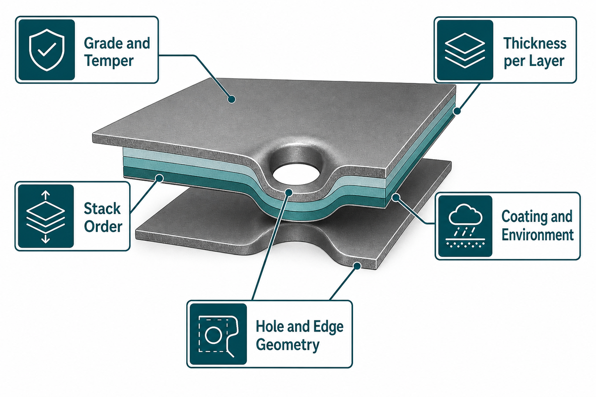
The sheet stack controls how a joint forms and where it fails. Record every layer’s grade, temper or hardness, thickness, coating, order, and exposure, then add hole method, tolerance, edge location, spacing, local stiffness, structural load path, and cyclic spectrum before carrying a catalog value into design review.
| Input | Mechanism it can change | Evidence to request |
|---|---|---|
| Thickness per layer | Thread engagement, rivet flare, local bending | Drawing-linked coupon stack |
| Grade and temper | Flow, cracking, bearing, pull-out | Material certificates plus actual samples |
| Stack order | Piercing and interlock formation | Fixed top/bottom orientation |
| Hole and edge geometry | Strip, spin, tear-out, distortion | Measured hole and edge records |
| Coating and environment | Friction, seating, corrosion compatibility | Finished-condition exposure review |
| Assembly stiffness | Load redistribution beyond one coupon | Assembly-level load path analysis |
Research on SPR makes the limitation concrete. One study tested a 3.0 + 3.0 mm AA5754-H111 stack, another used 2.5 + 2.5 mm AA6082-T6, and a 2025 paper compared five die designs on 1.5 + 1.5 mm AA5052; their findings stay with those specimens, rivets, dies, and load directions.
When not to approve a fastener: do not accept a nominal strength number when the local sheet, hole, formed interlock, coating, or assembly stiffness can control failure. Qualify the component, installation window, and assembled load path separately.
Self-Piercing Riveting vs Clinching: When Formed Joints Fit
A semi-tubular rivet forms the SPR interlock in the lower sheet, while clinching forms the sheets into an interlock without a separate rivet. Both are permanent routes that need a qualified stack, punch-and-die access, controlled tooling, surface acceptance, and finished-joint proof.
Screen SPR when
- The design accepts a separate rivet.
- The upper sheet can be pierced.
- The lower sheet can form a verified interlock.
- Rivet/die selection can be frozen for trials.
Screen clinching when
- The design prefers a fastener-free formed joint.
- Both layers can deform without unacceptable cracking.
- The formed button fits the surface envelope.
- Punch/die geometry can be controlled.
Neither route wins without the actual stack. Peer-reviewed results show that die geometry, stack order, material behavior, and the chosen load test can change how candidates rank; a deeper die or a larger-looking interlock isn’t automatically stronger.
Buyers who have passed this screen can translate the controlled stack into an SPR trial brief and check punch-and-die access against the production flange. The equipment discussion should begin with sample parts, access geometry, monitoring needs, and acceptance ownership rather than an unsupported universal process claim.
Trial boundary: freeze the sheet batch, layer order, rivet or tool revision, setting condition, and test direction. Changing any one of those inputs creates a new comparison condition.
Why Datasheet Values Do Not Qualify the Finished Joint
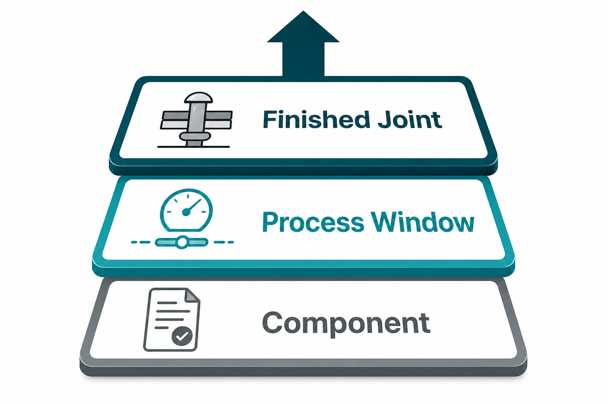
Datasheet values describe a component or a stated test condition; they do not qualify the buyer’s finished assembly. The frozen trial boundary from the previous comparison therefore becomes the starting point for qualification. Release review separates three evidence layers: component capability, repeatable installation within a process window, and joint-level performance on a defined specimen in the real load direction.
“Specifies the specimen dimensions and the tensile shear test procedure for single mechanical joints.”
| Evidence layer | What it can prove | What it cannot prove alone | Owner |
|---|---|---|---|
| 1. Component | Fastener material, geometry, declared rating | Strength of the buyer’s sheet assembly | Supplier plus design engineering |
| 2. Process window | Repeatable installation across controlled variables | System load redistribution or service life | Manufacturing and quality |
| 3. Finished joint | Performance against a defined specimen, direction, and criterion | Different stack, drawing revision, or duty cycle | Buyer’s engineering authority |
ISO 12996 defines specimen dimensions and a tensile-shear procedure for single mechanical joints, but it does not supply one universal acceptance load. The buyer must state specimen revision, load direction, conditioning, sampling, failure definition, and acceptance threshold.
One common failure is accepting a clean cross-section as final proof. Sections can track an established process once their relationship to performance is validated, yet published SPR work shows that familiar interlock dimensions may rank candidates differently from destructive load results.
Use the 4-Input Sheet Fastening Qualification Register as a Pre-Screen
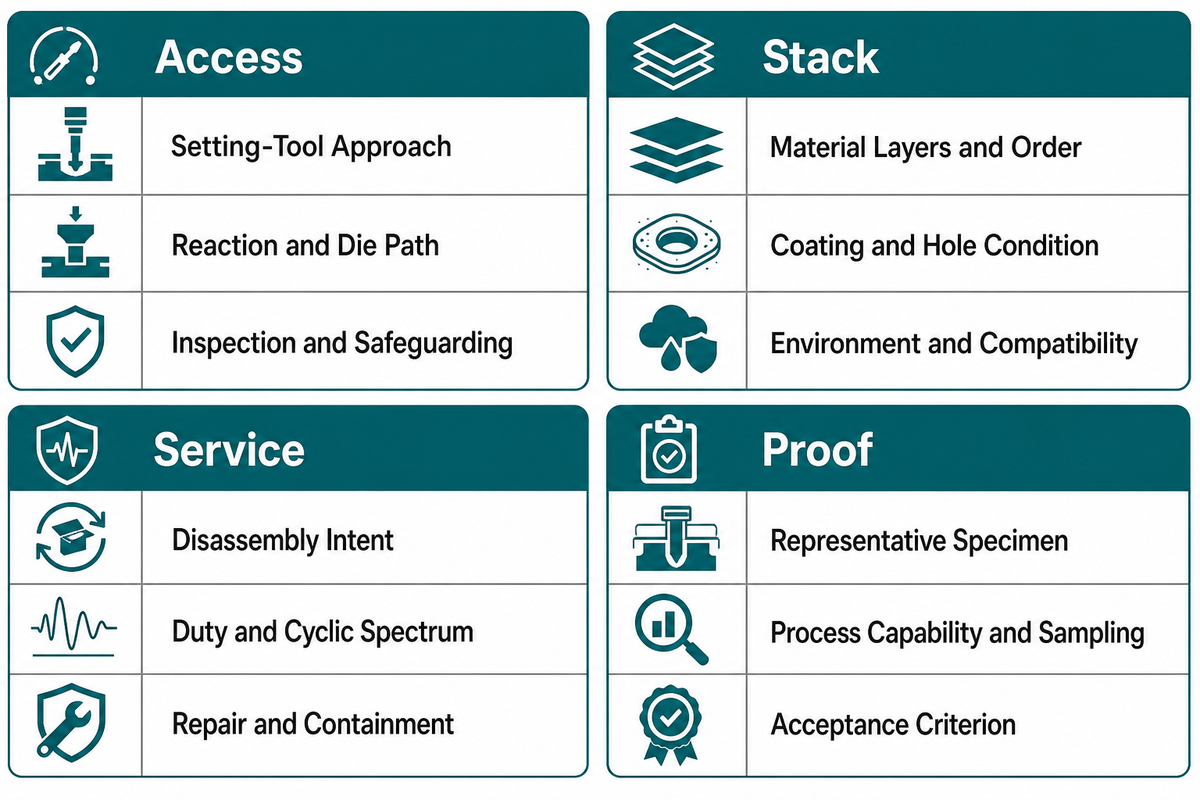
The 4-Input Sheet Fastening Qualification Register gives engineering, procurement, quality, and suppliers one controlled pre-screen. It turns the preceding gap between cross-section evidence and load results into four controlled inputs. The register binds Access, Stack, Service, and Proof to a drawing revision, decision owner, and open-risk list before a method advances to application-specific structural, regulatory, safety, and production qualification.
| Input | Record | Question that blocks release | Status / owner |
|---|---|---|---|
| Access | Setting-tool approach | Does the production head clear the final flange and fixture? | Manufacturing review |
| Reaction and die path | Where does installation force close? | Tooling review | |
| Inspection and safeguarding | Can the joint be checked without defeating the safety concept? | Quality + Safety review | |
| Stack | Material layers and order | Are grade, temper, thickness, and top/bottom order frozen? | Design review |
| Coating and hole condition | Does the trial match the finished part? | Process review | |
| Environment and compatibility | Are moisture, temperature, and galvanic pairs reviewed? | Materials review | |
| Service | Disassembly intent | Must the joint reopen without damage? | Product review |
| Duty and cyclic spectrum | Which loads and cycles represent service? | Analysis review | |
| Repair and containment | What happens to a rejected production joint? | Operations review | |
| Proof | Representative specimen | Which drawing and material batch does the coupon represent? | Quality review |
| Process capability and sampling | How will setting variation and rejected parts be recorded? | Manufacturing review | |
| Acceptance criterion | Who approves the limit, direction, and failure mode? | Engineering authority |
Consider a hypothetical battery enclosure with driver-side service access, a coated aluminium-to-steel stack, permanent panel attachment, and a coupon plus assembly-level cyclic proof plan. That record can expose a galvanic review or die-clearance problem before equipment comparison begins.
Important limitation: this register is an original buyer pre-screen, not a published standard and not a complete structural, code, regulatory, or machinery-safety qualification plan. Add the governing requirements and competent approval for the actual application.
If your team wants a guided first pass, use the joining-route pre-screen, then return the completed register to the drawing review.
Build the RFQ and Trial Plan Before Choosing Joining Equipment
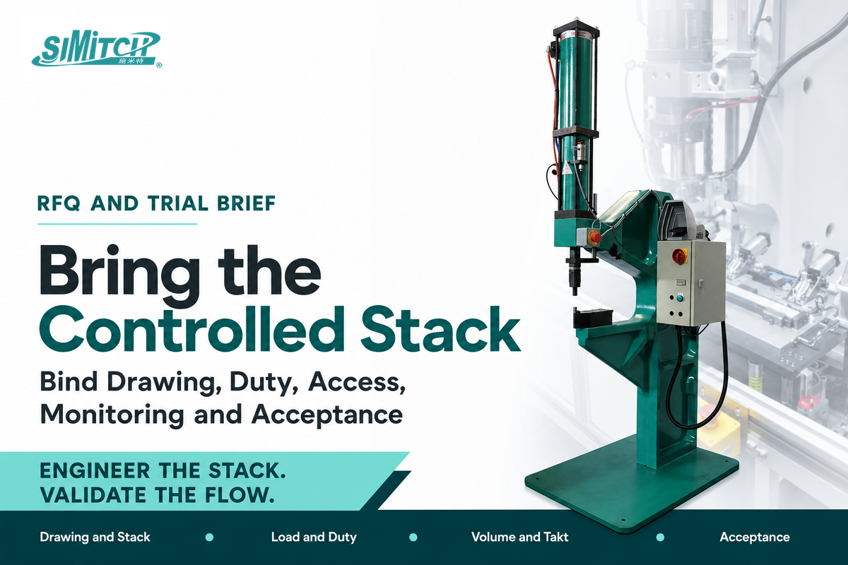
Useful equipment requests contain enough information to reproduce the intended joint and judge it. The completed register from that pre-screen becomes the RFQ’s controlled starting record. Send controlled drawings, representative materials, expected production duty, access and utility boundaries, safeguarding interfaces, monitoring needs, a trial protocol, and the named person who owns acceptance.
Copy the following eight rows into the quote request; every “range” stays buyer-defined until a representative trial supports it.
RFQ checklist: copy these into your quote request
| Parameter | Recommended range | Why it matters | How to verify |
|---|---|---|---|
| Drawing and stack | Exact controlled revision and layer order | Prevents sample drift | Drawing plus actual material batch |
| Load and duty | Buyer-defined directions and cyclic spectrum | Sets the proof case | Approved load document |
| Volume and takt | Buyer’s production range | Shapes feeding and automation | Production forecast and timing study |
| Access and footprint | Line-specific clearance limits | Eliminates unreachable tools | Layout and reach review |
| Utilities and controls | Site-specific limits and interfaces | Defines integration scope | Plant utility and controls schedule |
| Safety interfaces | Risk-assessment-defined boundary | Separates machine and line duties | Safeguarding and energy-control review |
| Monitoring and records | Buyer-defined signals and retention | Supports process evidence | Trial data export |
| Acceptance | Agreed specimen, sampling, and limit | Creates one release decision | Signed trial protocol |
Simitch’s supplied company brief describes a focus on intelligent joining equipment and system-level solutions across hydro-pneumatic boosters, precision servo pressing, Clinching, Riveting, SPAC, and SPR. That capability context does not establish a machine specification or a result for your stack; it explains why the RFQ should cover the joint, equipment, controls, and acceptance system together.
Use the parent view to scope rivet feeding, tooling, controls, and acceptance boundaries when the route is still open, or define force-displacement monitoring and cell-integration requirements when those functions belong in the trial scope. Capital approval should wait until the sample plan, interfaces, and acceptance owner are agreed.
Have a drawing and representative sheet stack?
Prepare the layer order, access envelope, service need, and proposed proof method for a focused discussion with an equipment supplier. Keep the route open until representative samples and agreed acceptance evidence support it.
Conclusion: Choose the Proof Path With the Fastener
Responsible sheet metal fastening decisions freeze the four pre-screen inputs, remove routes that fail service or access constraints, and assign proof before equipment selection. Keep component data, process capability, and finished-joint acceptance separate, then approve the route against one controlled drawing revision.
- Record: Access, Stack, Service, and Proof.
- Screen: compare feasible threaded, riveted, and formed routes.
- Qualify: test representative joints and close open risks with the named owner.
Don’t lock a supplier or tool while the load path, trial specimen, process controls, or acceptance criterion remains ownerless. The fastest quotation is useful only when every bidder is pricing the same joint and the same proof obligation.
Sheet Metal Fastening FAQ
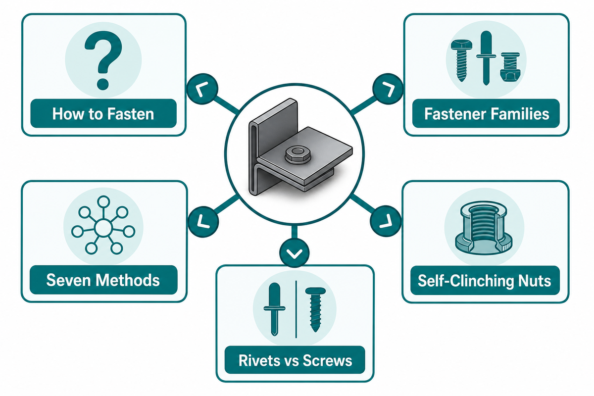
The proof obligation above also frames these common buyer questions about fastening methods, service, and joint qualification.
How do you fasten sheet metal?
View answer
Decide whether the joint must reopen, then record the sheet stack, load direction, installation access, and proof method. Screws, bolts, rivet nuts, and captive threaded hardware support serviceable routes; blind rivets, clinching, and SPR usually create permanent joints. Representative coupons are still needed because material, holes, edges, coatings, and tooling affect the result. For production, add the drawing revision, sample batch, process settings, inspection frequency, failure definition, and the person authorized to accept the joint.
What are sheet metal fasteners?
View answer
Sheet metal fasteners are hardware or formed features that hold thin metal parts together. Examples include screws, bolts and nuts, threaded inserts, rivet nuts, blind rivets, captive self-clinching hardware, and self-piercing rivets. Clinching belongs in the same selection discussion even though it forms an interlock without adding a separate fastener.
What are seven common sheet metal fastening methods?
View answer
Seven common families are sheet-metal screws, bolts with nuts, rivet nuts or threaded inserts, blind rivets, self-clinching nuts or studs, clinching, and self-piercing riveting. They differ in serviceability, hole preparation, one-side or two-side access, surface effects, and the evidence needed for acceptance. Treat the list as a taxonomy, not a strength ranking; the actual stack and proof plan decide which route survives.
How do self-clinching nuts work?
View answer
Press installation seats the hardware in a prepared hole, displacing sheet material into its retention features. Suitability depends on thickness, hardness, hole quality, edge geometry, support, push-out, and torque behavior.
Are rivets stronger than screws in sheet metal?
View answer
No universal ranking is valid. Screw performance may be limited by strip torque, thread damage, or local sheet deformation; a riveted joint may be limited by bearing, tear-out, mandrel behavior, interlock formation, or the sheet stack. Coating, edge location, joint stiffness, temperature, moisture, and cyclic loading can move the failure point again. Compare representative joints in the required load direction, retain rejected samples, and state the acceptance criterion instead of treating either catalog rating as a finished-assembly result.
About Simitch
Established in September 2006 in Taicang, Jiangsu, Simitch focuses on intelligent joining equipment and system-level solutions. Its supplied capability scope includes hydro-pneumatic boosters, precision servo pressing, and lightweight sheet-metal joining routes such as Clinching, Riveting, SPAC, and SPR for automotive components, energy storage, solar photovoltaic, home appliance, and HVAC applications.
References & Sources
- ISO 12996:2013, Mechanical joining, specimen dimensions and tensile-shear test procedure
- NIST, Review of Disassembly Systems for Circular Product Design
- Peer-reviewed comparison of mechanical joining methods and disassembly capability
- Jepps et al., SPR interlock volume and joint performance study
- Haque et al., multi-criteria evaluation of self-piercing riveted joints
- Zhang et al., 2025 study of die geometry in AA5052 SPR joints
- TWI, self-piercing riveting mechanism and process boundary
- TWI, bounded comparison of clinching and self-piercing riveting
![Hot-Melt Connection Molds & Equipment Guide [2026]](https://simitch.com/wp-content/uploads/2026/09/hot-melt-connection-molds-equipment-guide-featured-768x512.png)