Get in touch with Suzhou Simitch Machinery Co., Ltd Company

Hot-Melt Connection Molds & Heat Staking Machine Systems
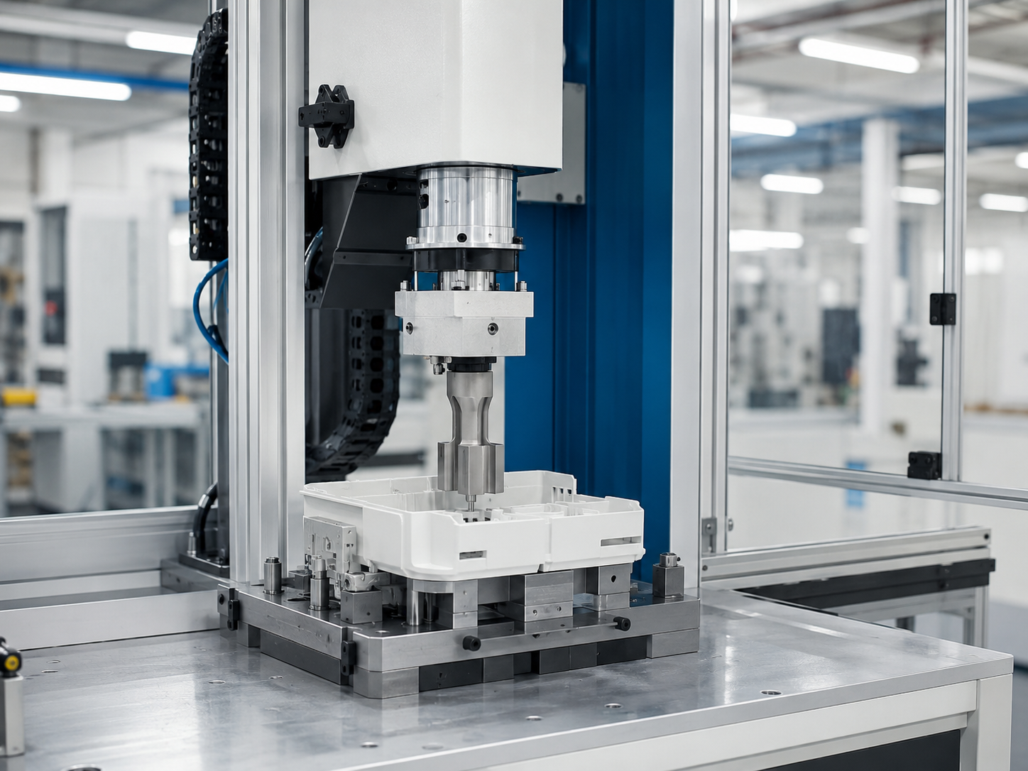
A heat staking machine is only one piece of a solid assembly operation. Simitch uses your part, joint geometry, output target and acceptance criteria to engineer your mold, thermal process, press infrastructure, guarding strategy and line interface.
Check Required Inputs
Send Your Part Drawing
Joint First
Part geometry and material define the process route.
Custom Tooling
Mold, fixture, forming head, and access are reviewed together.
Cell Fit
Manual, semi-automatic, integrated, or automated architecture.
Sample Gate
Application-dependent settings are verified before production scope.
Since 2006
Simitch’s machinery background began with sheet-metal connection equipment.
No Guesswork
Unprovided force, temperature, stroke, cycle, and price data are not invented.
Start With the Joint, Not a Generic Heat Staking Machine
Buy a press first, and it may heat, control, and move accurately while still forming an unstable head. That failure can begin because the plastic, boss volume, fixture contact, or cooling path was never qualified, so start with the plastic part and the retained component rather than a catalog model.
- Part and material
- Stake geometry
- Joint result
- Production context
- Process evidence
- Safety boundary
Part and material
Resin grade, fillers, color, surface treatment, molded condition, and mating-component material.
Stake geometry
Boss profile, available material volume, spacing, access direction, and nearby cosmetic or functional surfaces.
Joint result
Retention requirement, allowable deformation, head profile, visual limit, inspection method, and failure criteria.
Production context
Stake count, loading method, takt target, changeover frequency, shift pattern, and upstream/downstream interfaces.
Process evidence
Sample plan, trial variables, measurement method, acceptable window, control plan, and traceability requirement.
Safety boundary
Operator access, hot surfaces, moving tooling, guard opening, maintenance access, and local regulatory responsibility.
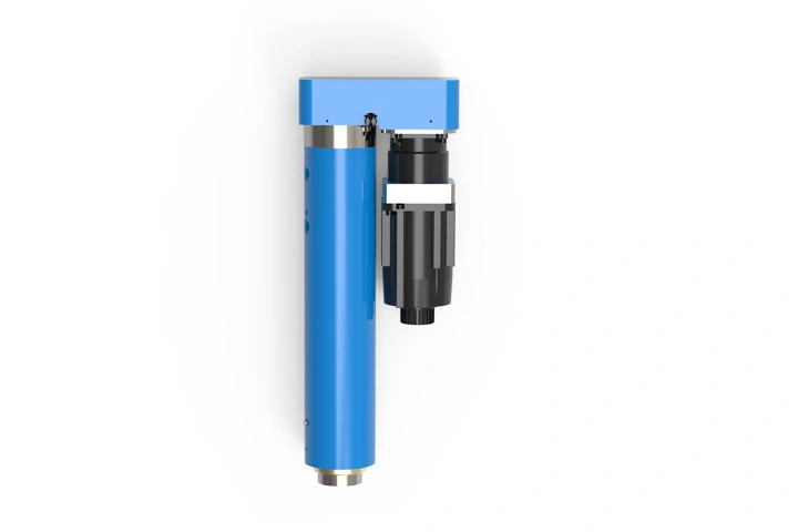
Heat and pressure soften and form a thermoplastic feature, but the final connection is governed by a coupled system. One 2026 peer-reviewed SLS PA12 study varied both force and temperature and found substantial changes in microstructure and strength, which supports one conclusion: one universal recipe isn’t defensible.
Evidence boundary
That study reported up to 33.6 MPa for its heat-staked SLS PA12 joints versus 39.9 MPa for turned reference specimens. Those values belong to that material, geometry, and test program; they aren’t Simitch machine specifications or expected customer results.
Once the resin, boss design, part support, and acceptance test are known, the heat staking process can move from assumption to a controlled feasibility plan. When those inputs are missing, the honest next step is an engineering review rather than a guessed equipment recommendation.
Use the Joint-to-Mold-to-Cell Qualification Map
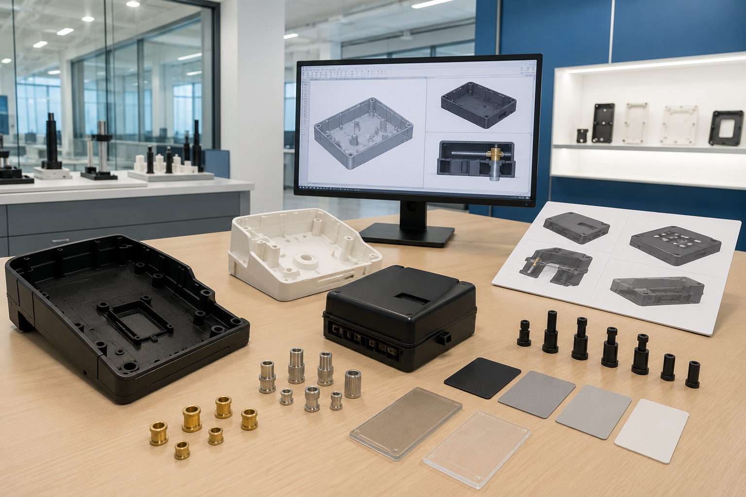
Our Joint-to-Mold-to-Cell Qualification Map turns six buyer inputs into six engineering decisions. It keeps tooling, machine format, safety, automation, and quality evidence connected throughout the proposal rather than treating each as a separate purchase.
Buyer Input
Engineering Question
Proposal Output
Evidence Needed
Part and joint geometry
Where can the tool approach, and how is the part supported?
Joint and fixture concept
2D/3D files, tolerance notes, representative parts
Thermoplastic and retained component
How will the material respond to local heating, forming, and cooling?
Trial variables and material-risk list
Resin grade, fillers, surface condition, material data
Stake count and distribution
Should stakes be processed together, in groups, or sequentially?
Tool layout and machine-load concept
Boss map, access envelope, assembly order
Appearance and joint quality
What deformation, flash, stress, or witness mark is acceptable?
Head profile and inspection plan
Golden sample, drawing notes, test requirement
Volume, takt, and loading
Which machine and automation format fits the production cell?
Benchtop, station, module, or automated-cell direction
Annual demand, shifts, takt, loading concept
Controls and traceability
Which process values, decisions, and results must be recorded?
Control, data, and interface scope
Protocol, record fields, retention and validation needs
The map also shows when sample feasibility should come before a commercial proposal. That matters when an actual molded part may differ from its CAD model because of warp, local sink, tolerance stack, or insert position.
Buyer advisory
Do not freeze a machine envelope until the fixture concept and tool access have been reviewed. ISO 12100:2010 treats machinery safety as a life-cycle risk-assessment and risk-reduction process, so operator access and foreseeable intervention belong in the concept stage.
Configure the Mold and Heat-Staking Tool Around the Part
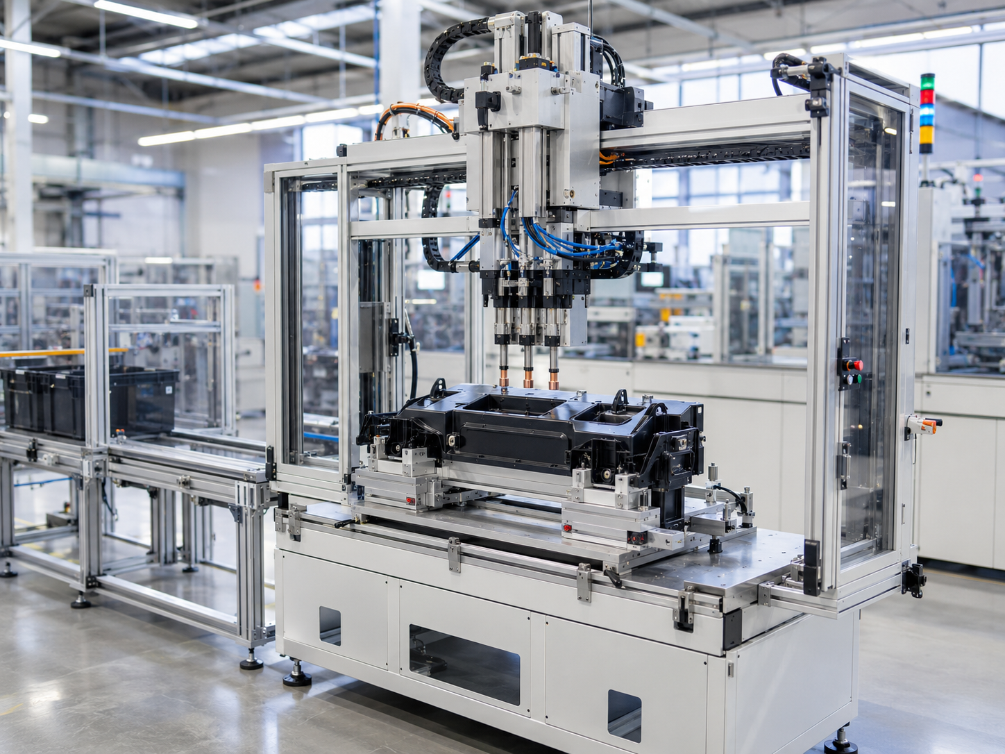
Head size, horn clearance, cycle time, and simultaneous staking must be resolved before equipment selection. A custom heat staking tool has to deliver energy and forming pressure while supporting the surrounding plastic, clearing nearby features, releasing without sticking, and preserving surfaces that matter.
- Boss material, profile, height, wall condition, and molded variation.
- Number and spacing of stake points, plus whether force should be applied together or in stages.
- Retained-component stiffness, hole geometry, positional tolerance, and available support surface.
- Tool approach, restricted space, nearby electronics, optical surfaces, coatings, or cosmetic faces.
- Changeover, cleaning, wear-part access, misload detection, and maintenance method.
Public heat-staking patent US8226871B2 describes how material properties, passage dimensions, retention geometry, and deformed-head overlap can alter the load path. The patent doesn’t prescribe a Simitch design, but it reinforces why geometry and material evidence must precede tool manufacture.
Accurate control of the heat at each stake is required to avoid incomplete forming or sticking, but tooling still has to absorb normal part variation. Trial work should therefore check formed-head geometry, retained-part seating, surrounding strain, release behavior, and repeatability across representative samples.
| Tooling input | Engineering effect | What Simitch needs | Decision after review |
|---|---|---|---|
| Boss and retained-part files | Defines forming volume, access, support, and interference risk | Native CAD plus drawing | Head profile and nest concept |
| Resin and filler information | Changes thermal response, flow, sticking, and cracking risk | Material designation and supplier data | Heating method and trial window |
| Appearance zone | Limits sink, marking, stringing, and transferred stress | Marked A-surfaces and visual standard | Tool contact and cooling strategy |
| Stake distribution | Changes head balance, force distribution, and fixture stiffness | Stake map and assembly sequence | Single, grouped, or staged tooling |
| Changeover plan | Changes datum scheme, module size, and verification steps | Part family and frequency | Dedicated or quick-change module |
Match Heat Staking Equipment to the Production Cell
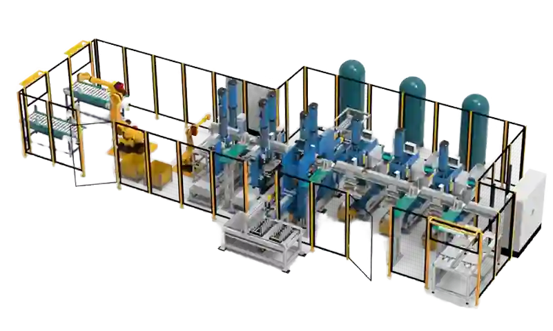
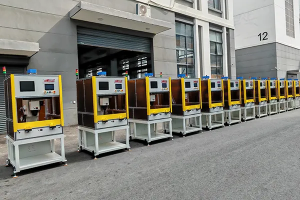
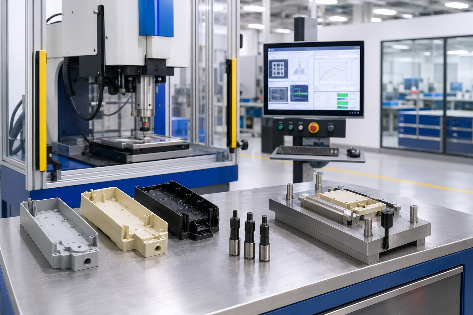
A heat staking press must be properly matched to the production cell as well as the joint. Loading method, operator access, stake count, changeover requirements, data exchange needs, inspection methods, and guard layout are among the factors that determine whether a benchtop machine, semi-automatic cell, integration module, or fully automated system represents a sound solution.
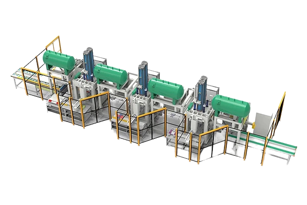
Production-cell PSP checkpoint
Mismatched cell architecture can create unsafe access, lost output, and repeated changeover failure because the joint process, operator work, guarding, and line interface were specified separately. Simitch reviews the cell against the part, output target, interface list, and ISO 12100 risk-reduction framework before recommending an architecture; send the layout and drawing so those constraints can be tested together.
Safety is a project input
OSHA 29 CFR 1910.212 requires guarding for point-of-operation hazards and identifies power presses among machines that commonly require this protection. The final solution should define hot-zone access, moving-tool access, loading, clearing, maintenance, and local compliance responsibility before the guarding concept is frozen.
One common assumption is that automation should always start with the largest platform. Modular architecture, swap modules, and staged investment may produce a cleaner technical and commercial fit when part families, takt, and validation needs are still evolving.
| Architecture direction | Loading and sequence | Control and data scope | Best discussion stage | Still required before quote |
|---|---|---|---|---|
| Benchtop / sample press | Operator-loaded, development-focused sequence | Recipe and basic cycle confirmation as required | Sample work, process development, lower-volume assembly | Fixture, operator method, quality checks, target output |
| Semi-automatic station | Manual load with controlled machine cycle | Part presence, sequence control, alarms, optional result handling | Repeat production with defined operator work | Guarding, sensors, poka-yoke, inspection, changeover |
| Integrated process module | Installed into an existing machine or robot cell | Mechanical, electrical, pneumatic, safety, and protocol interfaces | Existing line or machine-builder integration | Envelope, utilities, interface document, host ownership |
| Automated assembly cell | Automated transfer, process, verification, and unload | Line control, data records, fault recovery, upstream/downstream exchange | Higher-volume or multi-operation assembly | Takt study, logistics, validation, acceptance and service boundary |
Machine format and staking technology are separate choices. Hot-tool, hot-air, infrared, impulse, and ultrasonic methods deliver energy differently, while a manual or automated system describes how the production cell handles and controls the work.
Send the line layout and interface list to go with your part drawing.
Discuss Cell IntegrationControl the Complete Heat-Staking Cycle
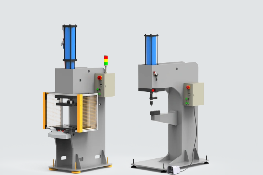
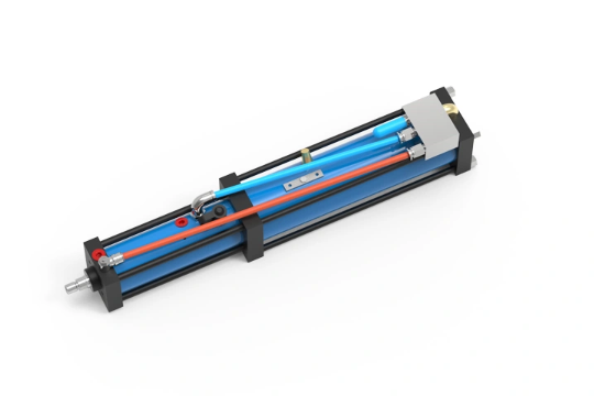
A stable thermal-staking process depends on the complete cycle, not a temperature setpoint in isolation. Temperature, force, cooling, material, and geometry interact, so more heat is not always a path to a stronger joint.
Locate and support
Confirm part presence, datum contact, retained-component seating, and boss position.
Heat
Deliver controlled thermal energy to the intended plastic volume without damaging nearby features.
Form
Apply the tool path and pressure needed to create the agreed head profile and overlap.
Hold and cool
Maintain support while the formed thermoplastic stabilizes and release risk falls.
Release and verify
Retract cleanly, check the joint, and record the result required by the control plan.
Variables to qualify
- Material condition, boss dimensions, molded variation, and retained-component fit.
- Energy delivery method, tool temp or energy input value, tool contact/placement behavior, dwell time.
- Tool motion, forming force/displacement, final position, and support stiffness.
- Hold time, type of thermal control (heat and cool), release temp, sticking/contamination.
- Head geometry, seating of formed head to supporting member, visual condition, part retention (force), part pull/strain and cracks, traceability record.
Delayed cracking between nearby inserts can appear after time and use, so inspection criteria matter. Forum reports cannot establish a universal cause, but they are a strong reason to include insert spacing, thermal history, strain inspection, and aging or functional tests in the feasibility plan when the assembly is sensitive.
Springer’s peer-reviewed SLS PA12 study provides a useful external example of coupled variables. Reported porosity decreased from 3.9% to 1.56% at 300 N and from 4.29% to 0.81% at 1000 N, yet those results remain specific to that experimental setup.
Variables to qualify: Material condition, boss dimensions, molded variation, and retained-component fit. Energy delivery method, tool temp or energy input value, tool contact/placement behavior, dwell time. Tool motion, forming force/displacement, final position, and support stiffness. Hold time, type of thermal control (heat and cool), release temp, sticking/contamination. Head geometry, seating of formed head to supporting member, visual condition, part retention (force), part pull/strain and cracks, traceability record. Delayed cracking between nearby inserts can appear after time and use, so inspection criteria matter. Forum reports cannot establish a universal cause, but they are a strong reason to include insert spacing, thermal history, strain inspection, and aging or functional tests in the feasibility plan when the assembly is sensitive.
Clean head geometry at the machine doesn’t automatically prove a durable assembly. Qualification should connect process values to the failure mode that matters: retention, distortion, cosmetic marking, electrical function, leak performance, or another part-specific criterion.
Compare Heat Staking With Other Joining Methods
Heat staking is not always the fastest, cheapest, or cleanest answer for every assembly. Selection should follow the load path, material pair, surface requirement, access, vibration sensitivity, particle concern, serviceability, and evidence required at acceptance.
Joint mechanism
Forms one thermoplastic boss into a retaining head
Part feature required
Accessible boss plus supported mating feature
Primary process concern
Heat path, head formation, cooling, sticking, local strain
When to keep evaluating it
Plastic-to-other-material capture, no separate fastener, controlled permanent assembly
Joint mechanism
Uses high-frequency vibration to soften or fuse the interface
Part feature required
Horn/anvil access and vibration-compatible part design
Primary process concern
Vibration transfer, energy balance, marking, sensitive electronics
When to keep evaluating it
Fast energy delivery and geometry suited to ultrasonic tooling
Joint mechanism
Melts two joining faces and fuses them under pressure
Part feature required
Two compatible joining surfaces with plate access
Primary process concern
Melt uniformity, plate contact, alignment, flash, cooling
When to keep evaluating it
Plastic-to-plastic sealed or structural interfaces
Joint mechanism
Adds a bonding layer between prepared surfaces
Part feature required
Bondable surfaces and controlled adhesive path
Primary process concern
Surface preparation, cure/set behavior, contamination, aging
When to keep evaluating it
Broad geometry or material combinations where adhesive validation is acceptable
Joint mechanism
Uses a separate screw, clip, rivet, or insert
Part feature required
Fastener access and load-bearing features
Primary process concern
Part count, torque, loosening, stress concentration, service access
When to keep evaluating it
Serviceability, familiar inspection, or reversible assembly
Plastics Technology notes that heat insertion and ultrasonic insertion soften plastic through different energy paths. Assembly Magazine also lists practical trade-offs such as clamping, stress marks, vibration damage, sticking, operator hazards, and variation.
The honest comparison
No row in this matrix declares a universal winner. A method is preferred only after the assembly geometry, material behavior, measurable acceptance criteria, production system, and commercial scope have been compared on the same basis.
Controlled press-fit route
If the assembly needs monitored force-distance pressing rather than a formed thermoplastic stake, review the BP Series precision assembly press.
Rivet-free sheet-metal route
If the joint is a sheet-metal interlock rather than a thermoplastic connection, compare pneumatic and servo clinching presses.
Unsure whether heat staking fits the joint? Start with a method-screening review.
Request a Method ReviewQualify the Process Before Building the Production System
A production machine should reproduce an accepted process, not discover basic feasibility after the equipment scope is fixed. This qualification path separates application risk from machine engineering and gives quality, equipment, and procurement teams a shared decision record.
STEP 01
Application review
Confirm part files, materials, joint intent, stake map, appearance limits, production target, and acceptance method.
STEP 02
Joint and tooling concept
Define support, access, head profile, forming method, process sequence, and unresolved risks.
STEP 03
Sample feasibility
Use representative parts to screen the process window and expose sticking, cracking, marking, fit, or variation.
STEP 04
Equipment definition
Translate the accepted concept into machine architecture, utilities, guarding, controls, handling, and data scope.
STEP 05
Acceptance plan
Connect measurable machine functions and joint results to the tests, records, and documents required at delivery.
STEP 06
Change control
Define which material, geometry, tooling, software, or line changes require review or requalification.
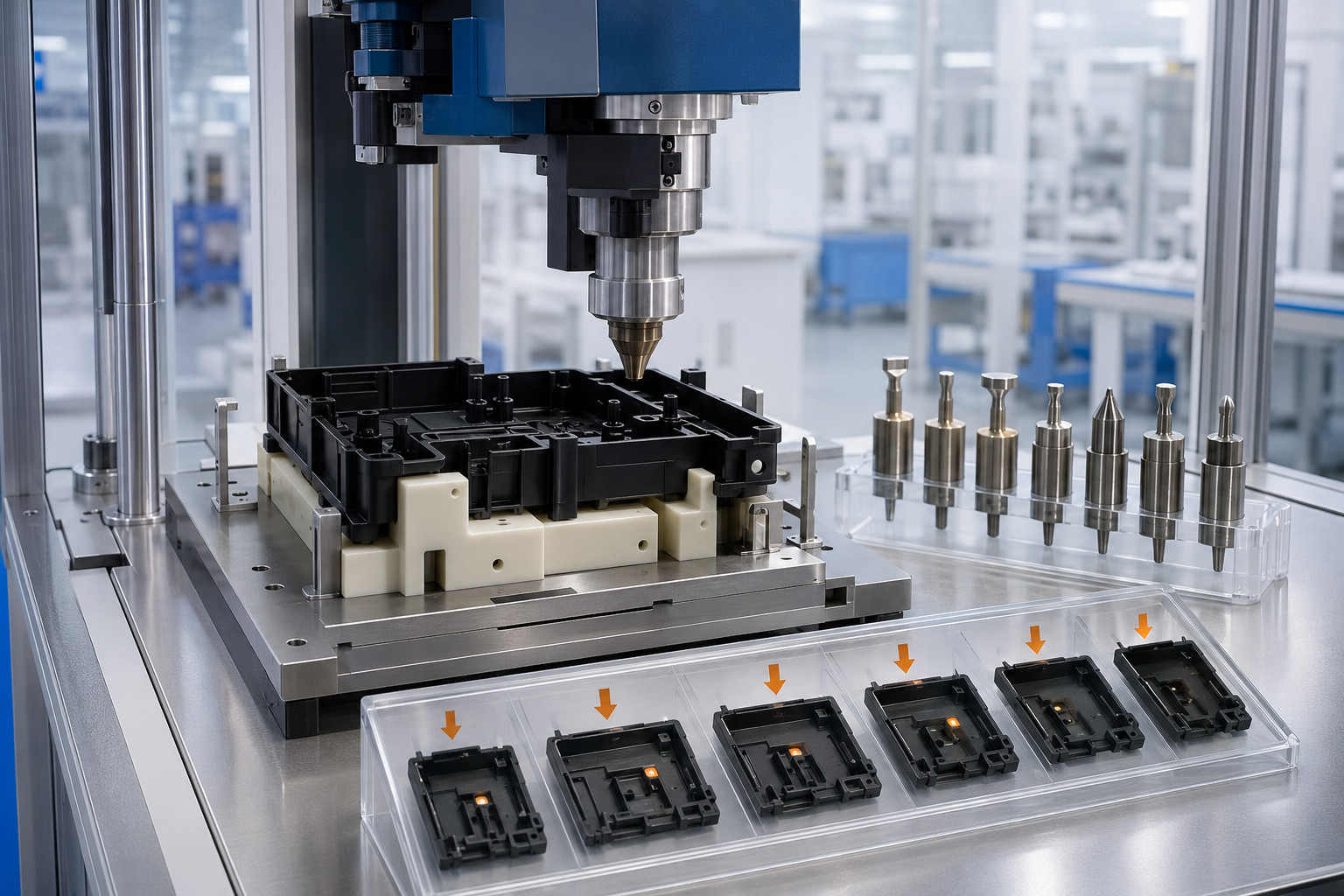
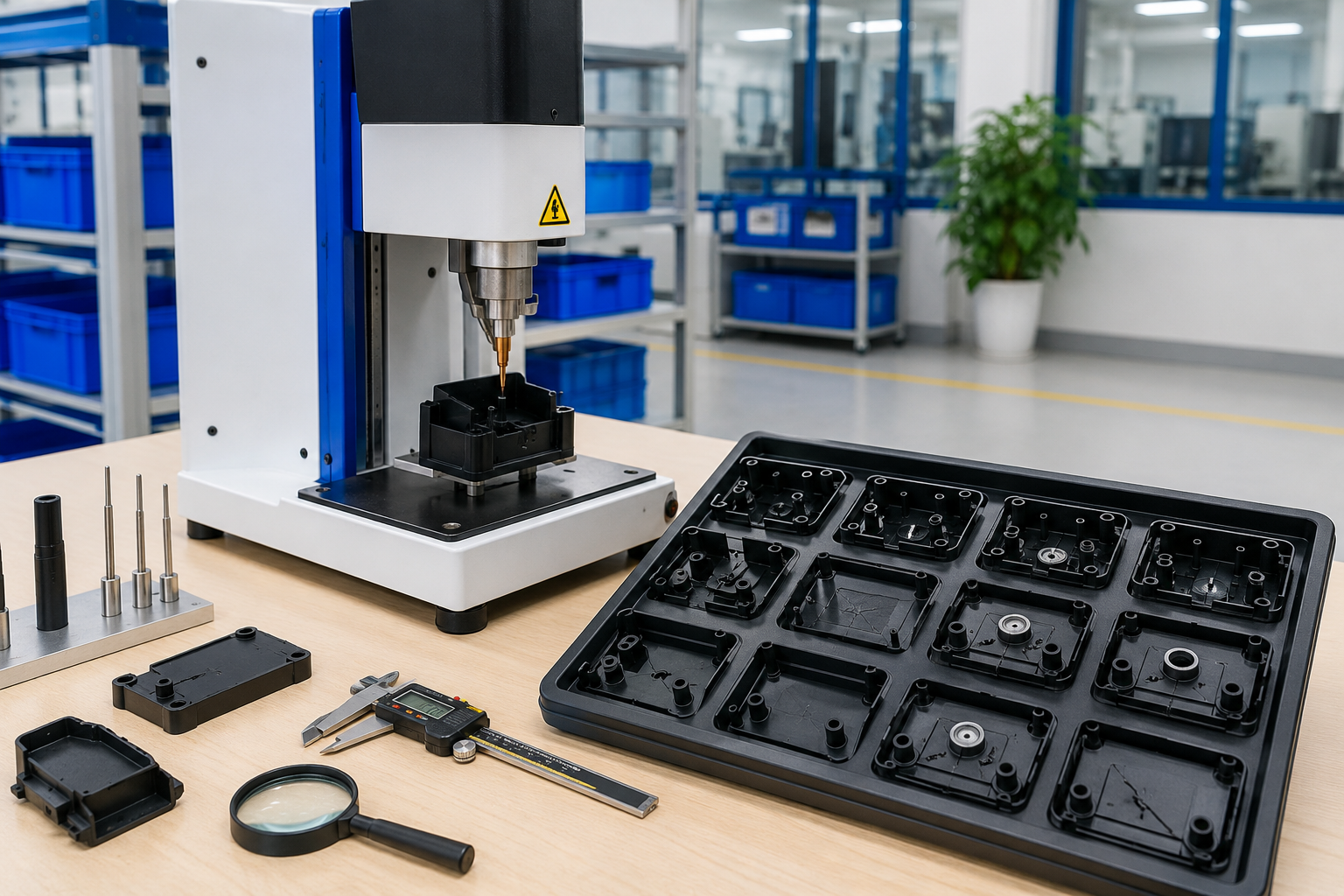
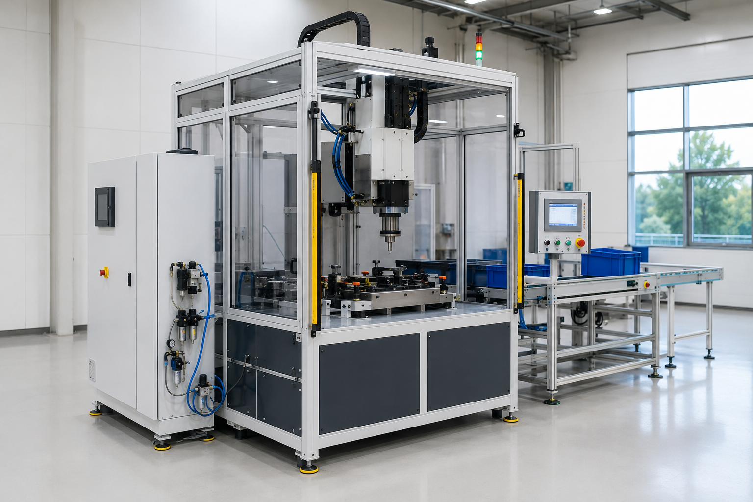
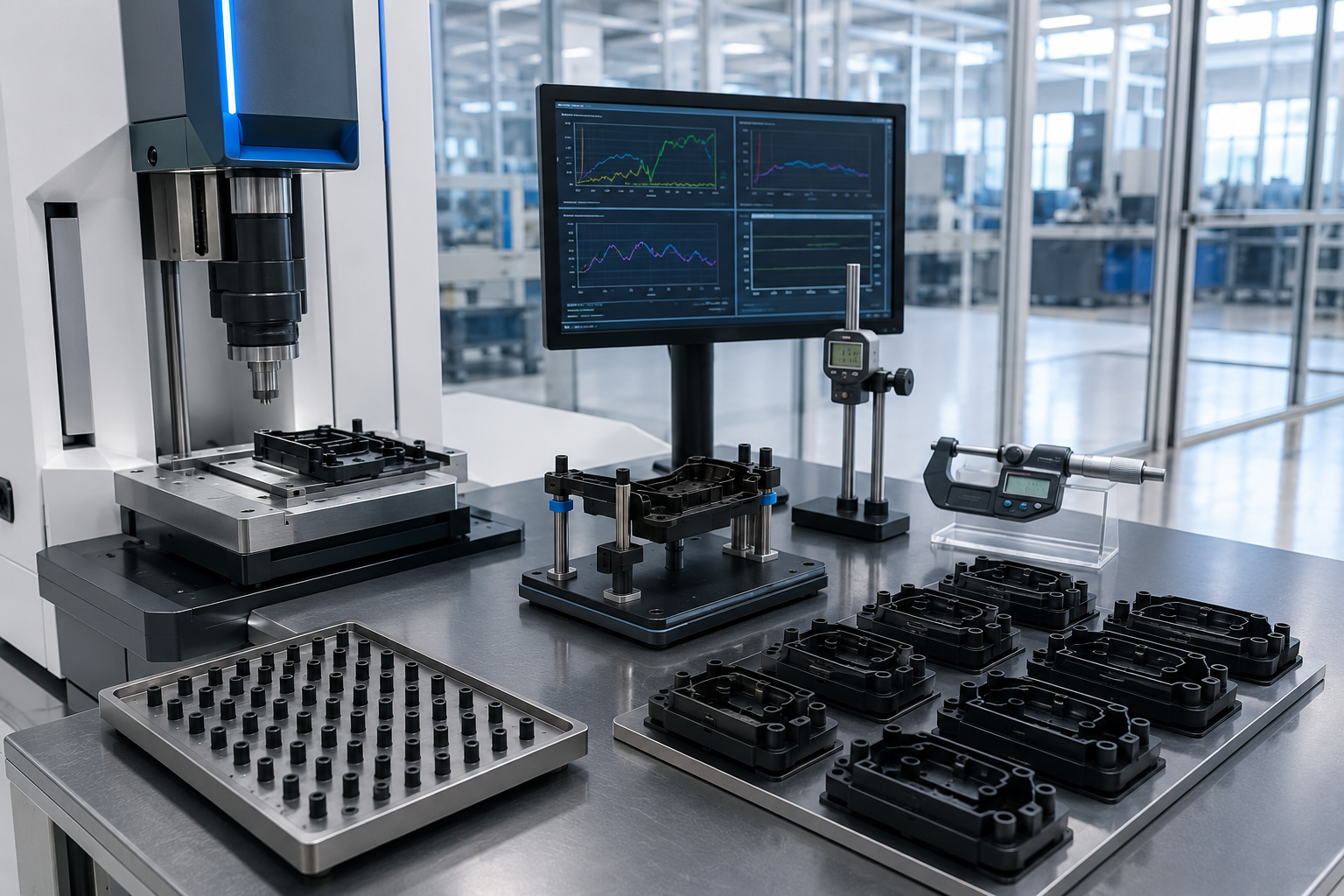
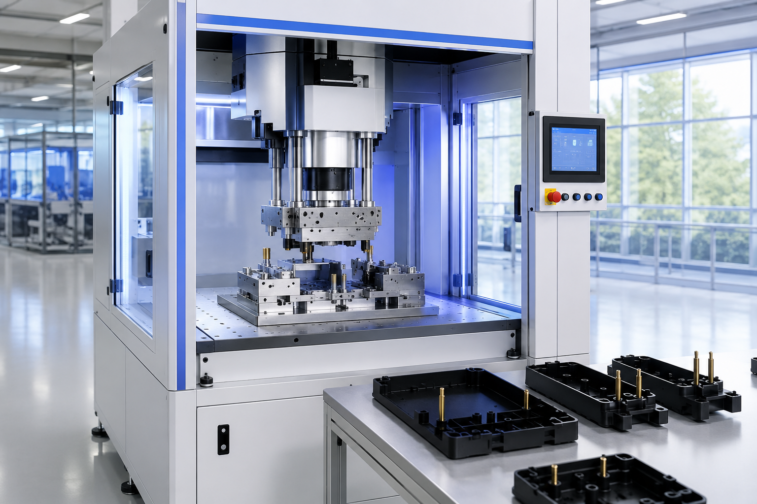
ISO 12100:2010 provides the broader machinery risk-assessment framework, while the experimental heat-staking evidence shows why process variables need an application boundary. Together they support a staged decision rather than a one-step equipment promise.
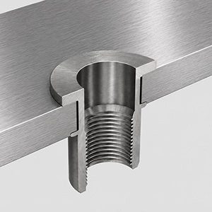
Evidence package to discuss
- Approved drawing revision, material identity, sample condition, and fixture datum.
- Trial settings and observations, formed-head dimensions, visual record, and failure notes.
- Retention or functional test method, sampling plan, acceptance limit, and traceability field.
- Machine sequence, guard concept, alarm response, changeover check, and acceptance-test scope.
This structure also protects the commercial discussion. Scope changes become visible because the proposal can identify which assumptions were verified, which buyer inputs remain open, and which tests belong before or after the production build.
Before committing to the production machinery and tooling, ask to see the procedures the supplier will use to qualify a design or approve a sample product.
Pass the Proposal Readiness Gate
A custom heat stake machine can’t be responsibly priced from a product label alone. Proposal maturity depends on the part, material, tooling, process, automation, machinery risk-reduction scope, data, and acceptance boundaries that the supplier is being asked to deliver.
| Status | Entry condition | Commercial meaning | Next action |
|---|---|---|---|
| Ready for configuration proposal | Drawings, material, joint, production, interface, and acceptance inputs are available | The system boundary can be defined without inventing core assumptions | Develop the tooling, machine, validation, and commercial scope |
| More application data required | One or more decisive inputs are missing or internally inconsistent | A price or delivery promise would carry hidden assumptions | Close the named gaps with documents, samples, or line information |
| Sample feasibility should come first | Material response, appearance, retention, geometry, or variation cannot be confirmed on paper | Process risk should be reduced before production equipment is frozen | Agree trial parts, variables, measurements, and a decision rule |
Bronze-Tier Cost Framework
7 InputsQuote scope is driven by part and tooling complexity, stake count and sequence, machine architecture, loading and automation, guarding and safety interfaces, controls and traceability, plus validation and acceptance work. No exact price, payback period, lead time, warranty, or savings percentage is published because no verified Simitch-specific data was supplied for those claims.
Press hardware is only part of the system. Tooling, fixture, process validation, guarding, interface engineering, documentation, and site acceptance can materially change the scope even when the basic thermal press appears similar.
Procurement check
Ask each supplier to separate included equipment, product-specific tooling, sample work, installation, training, data interfaces, acceptance tests, documentation, spares, and excluded responsibilities. This produces a comparable quotation without relying on a misleading headline price.
Application Fit Must Be Verified From the Part
Industry labels provide a starting point, but they don’t prove process fit. An automotive interior component, PCB housing, appliance assembly, and medical-device subassembly may all involve thermoplastic staking while imposing different cosmetic, contamination, validation, data, and safety requirements.
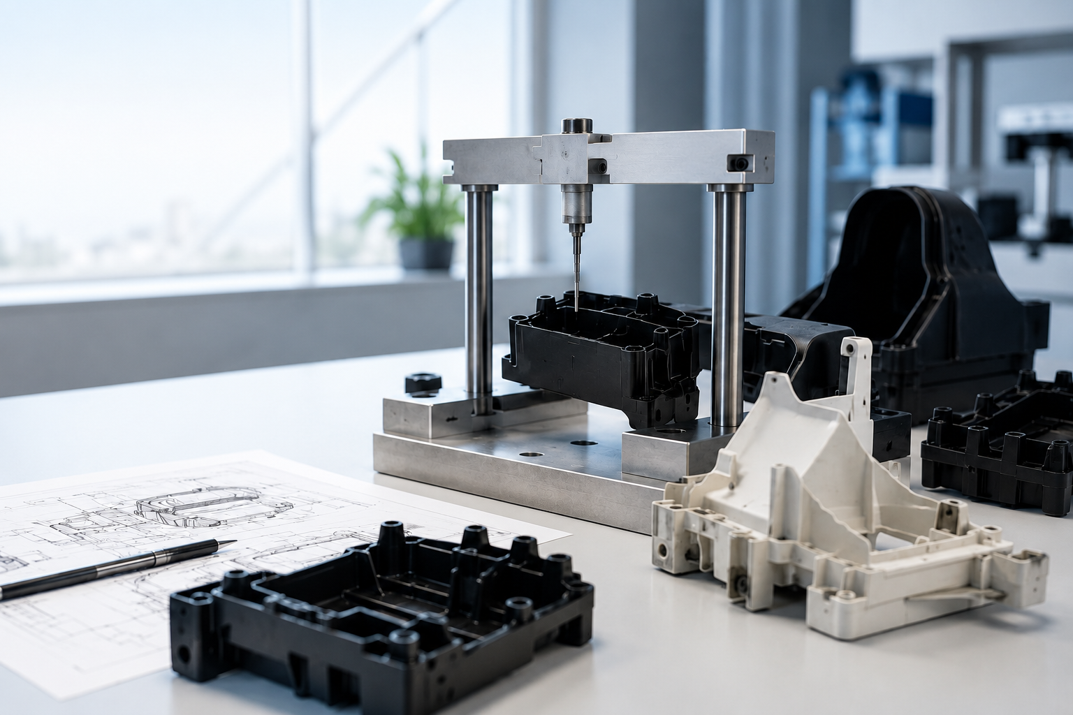
Trade-press reports describe electronics, automotive, and medical applications with complex geometry and sensitive components, but those examples aren’t Simitch case studies. They’re prompts for a better review: what’s the part, what must be retained, what can be heated, what can’t be marked, and how will the joint be accepted?
Hot-Melt Connection Molds & Equipment
Review the product-card route for custom molds and equipment, then bring the part-specific inputs into the engineering discussion.
Page categories can’t replace representative parts. Move the application to sample review when resin behavior, boss geometry, surface sensitivity, retained-component function, or long-term joint performance remains uncertain.
Why Discuss the Application With Simitch?
Suzhou Simitch Machinery Co., Ltd. was established in 2006 and began as a traditional mechanical equipment manufacturer focused on sheet-metal connection machinery. Simitch then introduced foreign clinching technology and accumulated practical experience in equipment production and application.
Established 2006
User-provided company history
Connection Machinery
Origins in sheet-metal joining equipment
Independent R&D
Technology introduction progressed to internal innovation
Core-Part Production
User states key equipment and core parts are produced independently
Continuous Development
With nearly 20 years of continuous development, Simitch reports that it progressed from technology introduction to independent research, development, and innovation. Simitch states that it has mastered core clinching and precision pressing technologies, obtained independent trademarks and multiple technical patents, and realized full independent production of key equipment and core parts.
Transparent capability boundary
These company facts don’t establish a heat-staking temperature range, force, stroke, accuracy, cycle time, installed base, certification, or customer result. Those product and application claims require separate first-party evidence and part-specific engineering confirmation.
That boundary is part of the value proposition. Simitch can use its connection-machinery and precision-pressing background to structure the discussion, while the project still advances through a drawing review, tooling concept, feasibility decision, machine definition, and agreed acceptance plan.
Bring the application evidence; Simitch will help define the engineering questions.
Start an Engineering ReviewPrepare These Inputs for an Engineering Review
Complete application inputs shorten the path from inquiry to a defensible configuration. They also prevent a heat staking machine manufacturer from hiding material assumptions, automation exclusions, or acceptance gaps inside a generic quotation.
Hover to Reveal Matrix ⟳
Input package
Minimum useful content
Decision it supports
Part definition
2D drawing, 3D model, assembly relationship, revision, tolerance, and marked surfaces
Access, support, datum, tool envelope, fixture concept
Material definition
Thermoplastic grade, filler/reinforcement, color, molded condition, retained-part material
Method screening, sample variables, sticking and crack risk
Stake definition
Boss profile, dimensions, count, spacing, distribution, head requirement
Tool layout, forming sequence, machine direction
Quality requirement
Retention or functional test, appearance boundary, measurement method, sampling, traceability
Acceptance plan and control/data scope
Production requirement
Annual volume, shift pattern, takt, loading, part family, changeover, line balance
Benchtop, station, module, or automated-cell architecture
Site and integration
Available footprint, utilities, robot or line interface, communication, safety ownership, destination
Mechanical, electrical, pneumatic, software, and guarding scope
Project evidence
Representative parts, golden sample, known failures, photos, existing process data, trial constraints
Proposal-ready or sample-first decision
If some fields are unknown, identify them rather than replacing them with an assumed specification. Simitch can then separate what’s ready for configuration, what needs additional data, and what should be proven through sample feasibility.
Hot-Melt Connection Engineering Tools
Heat Staking Project Readiness Scorecard
Assess material stack suitability, thermal limits, and cycle time feasibility before initiating tooling design.
Launch Evaluation ToolJoint-to-Mold-to-Cell Scope Builder
Map mechanical joint parameters directly to mold specifications, fixtures, and automated cell integration layouts.
Launch Scope BuilderJoining Method Screening Matrix
Evaluate heat staking against ultrasonic and mechanical fastening based on pull-strength limits and access envelopes.
Launch Screening MatrixHeat Staking Machine FAQs
What is the difference between a heat staking machine and a heat staking tool?
Machine or thermal-press hardware supplies motion, force, control, safety functions, and the production sequence. Its tool delivers and shapes the local heat-and-pressure condition at the plastic boss, while the fixture supports and locates the assembly.
What information is needed to design a custom heat-staking mold?
Start with 2D/3D part files, resin grade, retained-component material, boss geometry and distribution, access limits, appearance requirement, quality test, representative samples, and production context. Unknown material or joint behavior may trigger a sample-first review.
Can one heat staking machine handle different parts or molds?
It may be possible when the working envelope, load, process method, controls, guarding, datum strategy, and changeover verification support the entire part family. A shared machine shouldn’t be promised until each mold and process requirement has been compared.
Should I buy a manual heat staking machine, semi-automatic station, or integrated module?
Choose after reviewing volume, takt, operator work, part handling, stake count, quality checks, data needs, available line space, and integration ownership. A manual format can fit development or lower-volume work, while integrated equipment needs a complete interface definition and an application-specific machine-guarding review.
How is heat staking different from ultrasonic welding?
Heat staking reforms a thermoplastic feature into a mechanical retaining head. Ultrasonic processes use vibration to soften or fuse material, so horn access, vibration transfer, energy balance, part design, electronics sensitivity, appearance, and validation needs may lead to different decisions.
What affects heat-staking cycle time and proposal cost?
Cycle and scope depend on material response, boss geometry, stake count, simultaneous or staged processing, heating and cooling, handling, sensing, inspection, changeover, guarding, controls, data, and validation. Simitch should review these inputs before offering an application-specific estimate.
Can multiple staking points be processed in one cycle?
Multiple points may be processed together when tool balance, available force, heat delivery, part support, boss variation, access, and acceptance results are controlled across every point. Widely spaced or sensitive stakes may favor grouped or sequential processing.
How does the cooling cycle work?
Formed thermoplastic is supported while it stabilizes, then the tool retracts without unacceptable sticking, stringing, smearing, or head distortion. Cooling method, hold condition, and release point must be qualified for the material, tool, and joint.
What materials are typically used in heat staking applications?
The formed feature must be a thermoplastic that can be softened and reshaped under the selected process. The retained component may be plastic, metal, a PCB, or another material, but resin grade, fillers, coatings, heat sensitivity, and geometry must be reviewed.
Can Simitch confirm operating parameters before reviewing the part?
No defensible final temperature, pressure, force, displacement, cooling, or cycle setting should be confirmed without the material, geometry, tooling concept, and acceptance test. Responsible engineering defines the inputs, screens feasibility, and then confirms the process window.
Is your question application-specific? Send the part rather than guessing the answer.
Ask Simitch Engineering