Get in touch with Suzhou Simitch Machinery Co., Ltd Company


Updated August 2026
For product-family context, see SIMITCH pneumohydraulic drive cylinders.
Pneumatic & Servo Clinching Presses are often compared as if the drive label decides joint quality. It doesn’t. Drive architecture changes how force and motion are produced, what variables can be programmed, and what production data may be captured. Joint approval still has to come from the real sheet stack with the selected punch, die, access geometry, and acceptance tests.
Direct answer: Choose a pneumatic, pneumohydraulic, or servo-electric clinching press from the evidence the process must produce. A stable, low-mix application may be served well by a simpler pneumatic or pneumohydraulic route. A servo-electric axis deserves closer evaluation when programmable motion, frequent recipe changes, or cycle-level force-displacement records are genuine requirements. Neither route is approved until the joint and the machine are validated.
Keep these four boundaries visible
- Drive capability isn’t joint proof. Programmable motion or a clean curve can’t replace sectioning and the mechanical test required by the application.
- “pneumatic” can hide different architectures. Direct-air and pneumohydraulic force paths shouldn’t be treated as identical.
- Energy claims need one measurement boundary. Compare utilities per accepted joint, including rejects and idle operation.
- A drive change is a machine change. Frame loads, tooling, controls, safeguarding, measurement, and validation all need review.
Pneumatic vs Servo Clinching Presses at a Glance

The practical difference isn’t “simple versus advanced.” It’s how each architecture creates force, controls the ram, and exposes process evidence. Direct pneumatic cylinders respond to compressed-air pressure and their mechanical arrangement. Pneumohydraulic units use air to actuate a hydraulic force stage. Configured servo-electric joining axes convert controlled motor motion through a mechanical drive and can pair that motion with force and displacement evaluation.
Those differences affect recipes, changeovers, monitoring, utilities, and maintenance. They don’t set the required neck thickness, interlock, lap-shear result, or service performance of the clinched joint. Those acceptance criteria belong to the part and its duty.
Illustrative running example: Plant Delta begins with a 30 kN process target and a 2.0 mm final-displacement field, but treats both as trial inputs until coupon results establish the accepted window.
| Decision field | Direct pneumatic | Pneumohydraulic | Servo-electric | What this does not prove |
|---|---|---|---|---|
| Force path | Compressed air acts on a cylinder | Air actuates a hydraulic force stage | Motor motion is converted through a mechanical drive | That the real sheet stack will form an acceptable interlock |
| Motion program | Usually governed by valves, stops, pressure, and circuit design | Fast approach and force stroke depend on the selected circuit | Position, speed, and force-related functions may be programmable | That the programmed path is safe for the tooling or part |
| Production data | Sensors can be added around a defined process | Pressure, force, position, or cycle signals depend on configuration | Force-displacement evaluation can be integrated in a joining system | That a recorded curve equals joint strength |
| Utility boundary | Plant compressed air | Compressed air plus hydraulic force conversion | Electrical power and drive electronics | A universal energy-cost advantage |
| Maintenance focus | Air quality, leaks, seals, valves, alignment | Air circuit plus hydraulic seals, fluid condition, and intensifier | Drive train, lubrication, sensors, cabling, parameter control | Actual availability or lifecycle cost at your plant |
| Changeover control | Mechanical setup and verified pressure settings | Circuit settings plus force-stage setup | Governed recipes plus verified physical tooling | That a saved recipe matches the installed tooling |
| Validation path | Coupons and tests from the production stack | Coupons and tests from the production stack | Coupons, tests, and correlated process records | That more data replaces physical joint approval |
| Safety boundary | Machine-level risk assessment and safeguarding | Machine-level risk assessment and safeguarding | Machine-level risk assessment and safeguarding | That the drive architecture makes the cell safe |
Kistler’s servo joining documentation describes a system built around a joining module, servo amplifier, and force-displacement evaluation. That’s useful evidence of what a configured servo system can do, but it isn’t a promise that every servo press includes the same sensing, cutoff functions, data export, or accuracy.
Three Drive Architectures Buyers Often Collapse into Two
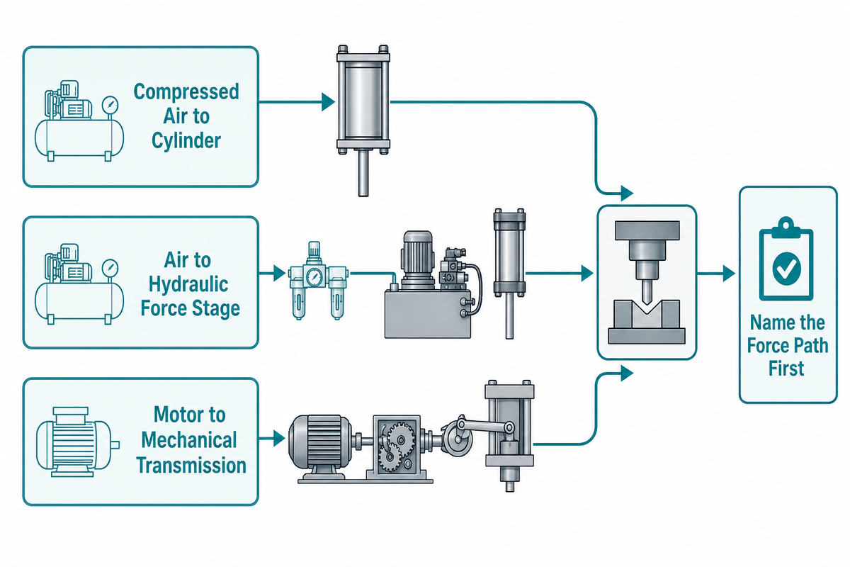
With that drive-and-evidence boundary established, calling every air-supplied press “pneumatic” hides a decision that affects sizing, controls, and service. Name the force path first. Then compare the configuration that will actually be quoted.
Direct pneumatic actuation
A direct pneumatic press uses compressed air acting on a cylinder to move and load the tooling. Its behavior depends on piston area, available pressure and flow, valve sizing, restrictions, mechanical stops, compliance, and the load curve. It can be fast and mechanically straightforward for a suitable force range, but air compressibility and plant pressure variation must be considered when the application needs a narrow process window.
Pneumohydraulic force multiplication
A pneumohydraulic or hydro-pneumatic unit normally uses air for motion and to actuate a hydraulic power stroke or intensifier. Sequence details vary by design. Its appeal is not that “air becomes hydraulic”; it is that the system can combine an air-supplied approach with a compact high-force stage. It should not be grouped with fully hydraulic presses, which use a different utility and force path. Buyers should request the fast-travel stroke, force-stroke behavior, available output at the stated air supply, fluid service requirements, and the signals exposed to the controls.
Servo-electric joining axis
A servo-electric axis uses a controlled motor and mechanical transmission, often a screw-based joining module, to move the ram. A complete system may also combine position feedback with a load cell and evaluation software. That combination can support different motion profiles, force or position cutoff, curve evaluation, and cycle records. Each required capability must be present in the selected hardware, controls, software, and data interface.
Specification rule
Replace the question “Is it pneumatic or servo?” with four fields: energy input, force-conversion path, controllable motion variables, and available process signals.
For the wider process, tooling, access, and equipment-family context, use the clinching machines and equipment guide. This article stays with the drive and evidence decision.
Normalize quote-sheet vocabulary before comparing offers
RFQs rarely use one stable taxonomy. A familiar phrase may describe the energy source, actuator, frame, joining method, controller, or an entire cell. Record the supplier’s exact wording, then translate it into the force path, motion variables, sensors, tooling, interfaces, and acceptance evidence. The vocabulary map below is a translation aid, not a claim that the listed terms are equivalent.
| Label group | Phrases you may encounter | What to define |
|---|---|---|
| Drive and actuator | pneumatic clinching machines; pneumatic systems; pneumatic cylinder; hydraulic system; hydraulic cylinder; hydraulic clinching; pneumatic and hydraulic; electric press; electric servo; full servo; servo motor; servo drive; planetary roller screw; ball screw or roller screw; toggle | Energy input, force conversion, usable stroke, force ranges, motion profile, thermal duty, and service boundary |
| Machine and frame | C-frame; press frames; assembly presses; press machine; press equipment; existing press; new servo press; press supplier; machine builder; tonnage; kN | Load path, deflection, shut height, access, duty, integration scope, and rated press force |
| Tool and joining method | clinching systems; clinching tool; press tooling; tools used; sheet metal joining; joining sheet metal; metal assembly; metal sheets; deform; emboss; fastening; fastener; rivet; spot welding | Actual clinching process, material stack, punch/die geometry, access, joint features, and physical test method |
| Control and selection | monitoring system; process monitoring system; quality control; quality assurance; control of force; force and position; precise force; press operation; servo press applications; right press; correct press; cost-effective; energy costs | Sensor chain, limits, reaction plan, data retention, utility boundary, and decision owner |
For an automotive or other high-volume sheet metal industry line, these definitions also need to state whether cycle time covers handling and changeover. Otherwise two offers can use similar labels while assigning very different work to the plant.
What the Drive Changes, and What It Cannot Prove
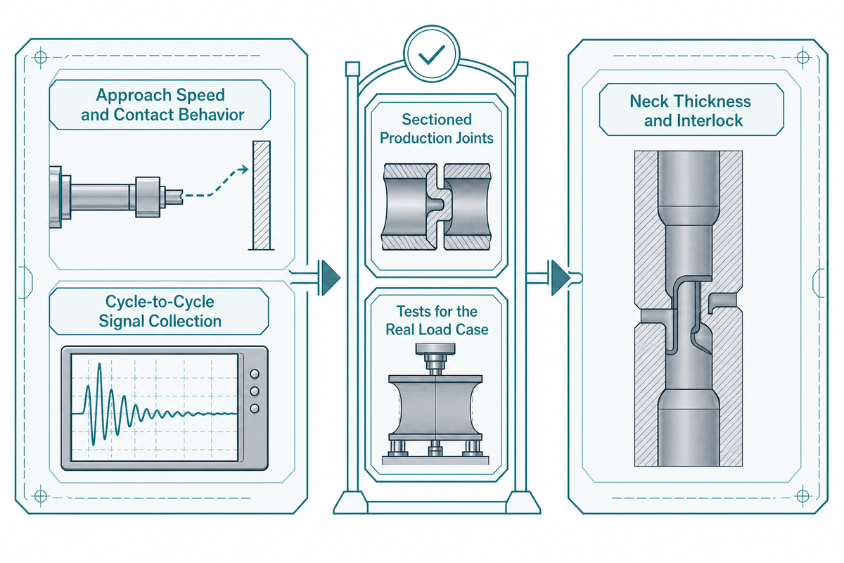
The drive changes how motion and force are controlled, which process signals can be captured, and how recipes are governed. It cannot certify the material stack, neck thickness, interlock, destructive-test result, fatigue life, or safety of the complete cell. Those outcomes need part-specific validation and machine-level risk assessment.
What is the difference between a servo press and a pneumatic press?
With the three force paths separated, pneumatic presses control motion through an air circuit, cylinder geometry, pressure, flow, valves, and mechanical limits. Servo presses use a motor-driven axis whose position, speed, and force-related functions may be programmed and recorded for production.
Finer motion control and richer cycle data become possible when the complete servo system includes the necessary sensors and evaluation. For a stable part mix and a proven process window, a pneumatic route may still meet the evidence requirement with a simpler control and sensor package.
For clinching, the drive can influence approach behavior, loading rate, final position, peak force, dwell, return motion, recipe changes, and the data available for monitoring. Drive choice alone can’t determine whether the material flows without cracking, whether the neck is thick enough, whether the interlock is adequate, or whether the joint survives its service load.
Peer-reviewed clinching work identifies neck thickness and interlock as important geometric characteristics and shows that tooling and process parameters change material flow. Another integrity study describes visual checks, joint geometry, destructive testing, and simultaneous force-displacement collection. In practice, the curve helps observe the process while the accepted physical joint remains the reference.
| The drive can influence | The drive cannot certify by itself | Required confirmation |
|---|---|---|
| Approach speed and contact behavior | Tool alignment or sheet support | Tooling setup and part-fixture review |
| Force or position cutoff | Neck thickness and interlock | Sectioned joints from the production stack |
| Cycle-to-cycle signal collection | Lap-shear, cross-tension, fatigue, or service behavior | Tests selected for the real load case |
| Recipe control and changeover | Correct material, sheet order, or coating condition | Material verification and controlled change management |
How Force-Displacement Monitoring Becomes Production Evidence
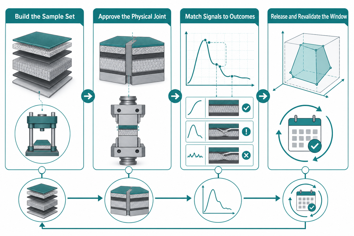
Force-displacement curves become useful as process evidence only after their features have been connected to physical joints. Good-looking curves from unknown joints aren’t masters, and unusual curves from accepted joints aren’t automatic rejects. The process team needs a controlled correlation exercise.
The 4-Step Curve-to-Coupon Correlation Chain
- Build the sample set — run the intended materials, thickness order, coating, tooling, orientation, support, and machine settings. Include expected variation and known off-condition samples when it’s safe to create them.
- Approve the physical joint — inspect appearance and section geometry, including bottom thickness (BTM) when it is part of the control plan, then perform the destructive or functional tests required by the load case. Record which coupons are accepted, marginal, or rejected.
- Match signals to outcomes — compare contact position, force rise, displacement at selected force, peak force, final position, and other configured features with the coupon results. Keep only features that separate meaningful process changes.
- Release and revalidate the window — set limits, define alarm response, and repeat the correlation after material, tooling, maintenance, software, fixture, or drive changes that may move the process.
Can I check clinching points using process monitoring?
Yes, process monitoring can compare each cycle with a validated signal window and flag deviations for action. It works best when the monitored features have already been correlated with accepted and rejected joints made from the real production stack. Monitoring can’t reveal every defect, and a normal-looking curve doesn’t replace destructive testing or periodic section checks where they’re part of the control plan. Define what an alarm stops, what it quarantines, who reviews it, and what evidence permits restart.
| Observed change | Possible process change | Confirmation check | Do not assume |
|---|---|---|---|
| Contact position shifts | Stack thickness, seating, fixture, or tool position changed | Measure stack and inspect support/alignment | That the sensor alone identifies the root cause |
| Force rises earlier | Material condition, friction, tool wear, or obstruction changed | Inspect material, lubrication/coating, and tooling | That higher force means a stronger joint |
| Final displacement moves | Bottom thickness, stack, compliance, or setting changed | Section samples and verify machine/tool setup | That one final-position limit covers every material |
| Peak force drifts | Pressure/drive, material, alignment, friction, or tool condition changed | Check utilities, calibration, setup, and coupon results | That the drive is the only variable |
Use the 7-Axis Drive-to-Evidence Matrix, Not a “Better Press” Ranking
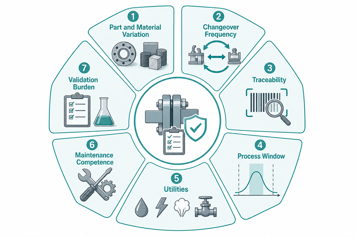
The useful question isn’t which technology wins in general. It’s which configuration can produce the required joint, control the real variation, and leave the evidence your plant must retain. Complete this matrix with production, QA, maintenance, controls, and finance in the same review.
| Decision category | Simpler route remains credible when | Servo evaluation moves up when | Evidence to request |
|---|---|---|---|
| 1. Part and material variation | One stable stack and controlled supply dominate | Many approved stacks need separate motion/force recipes | Stack list, tolerances, recipe control plan |
| 2. Changeover frequency | Setups are infrequent and mechanically verified | Frequent variants make controlled parameters and access rights valuable | Changeover method, approval steps, error-proofing |
| 3. Traceability | Batch checks and selected cycle signals meet the quality plan | A force-displacement record is needed for each joint or part | Record fields, retention, part/joint identifier |
| 4. Process window | The proven window is broad relative to controlled variation | Motion segments or cutoff features need close control | Correlation report, limits, measurement uncertainty |
| 5. Utilities | Clean, stable compressed air is available at measured cost | Air capacity or leakage is a plant constraint and electrical service is suitable | Measured air/electric use over the same shift boundary |
| 6. Maintenance competence | The team can sustain the air/hydraulic circuit and spares | The team can support drives, sensors, software, backups, and calibration | Skills matrix, spares, service response, recovery plan |
| 7. Validation burden | A simple validated setup meets customer and internal controls | Audit records, recipe governance, and cycle evidence reduce a real approval burden | Validation protocol, access control, change log |
| Matrix output | Document why the simpler route closes all seven categories | Document which unmet category the servo configuration closes | Signed decision record, open risks, test owners |
Decision rule
Select the least complex configuration that forms the accepted joint, controls the known variation, and produces the required evidence. Complexity without an evidence need becomes maintenance burden; simplicity without enough evidence becomes quality risk.
Once the matrix is complete, compare it with SIMITCH’s pneumatic and servo clinching press solutions. Available press families, configurations, application review, and quotation remain the commercial Page’s job.
Compare Energy, Cycle Time, and Maintenance Without Universal Percentages
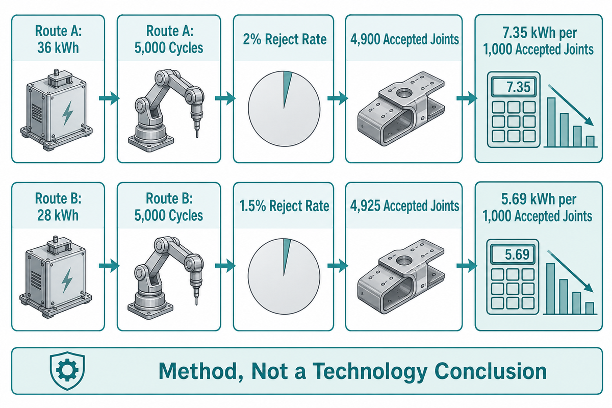
Claims such as “servo saves a fixed percentage” aren’t portable from one machine or plant to another. Results change with duty cycle, idle time, compressor efficiency, leakage, hydraulic-unit behavior, motor sizing, motion profile, rejects, and the boundary used for measurement. Compare routes per accepted joint over the same production window, and treat vendor-documented servo capabilities as configuration evidence rather than a universal savings result.
The Boundary-Normalized Utility Worksheet
Measure the energy assigned to the press route, total cycles, accepted joints, idle hours, changeover time, planned maintenance, and unplanned downtime. Record press force in kN, displacement in mm, motion time in ms, air pressure in bar, electrical energy in kWh, and reject rate in %. For the illustrative Plant Delta case, the field-format check reads 30 kN peak force, 2.0 mm final displacement, a 500 ms motion segment, 6 bar inlet pressure, 0.02 kWh per cycle, and 2% rejects; those values are placeholders, not acceptance limits. For compressed air, use a plant-approved conversion from measured air volume and pressure to compressor electrical energy rather than treating air as free. For a servo system, include the complete joining-cell boundary agreed for the comparison, not only the motor nameplate.
Illustrative calculation, replace every value with plant measurements
Route A: 36 kWh allocated to the press route, 5,000 cycles, and a 2% reject rate. Accepted joints = 5,000 × 0.98 = 4,900. Energy per 1,000 accepted joints = 36 ÷ 4,900 × 1,000 = 7.35 kWh. Route B: 28 kWh, 5,000 cycles, and a 1.5% reject rate. Accepted joints = 5,000 × 0.985 = 4,925. Energy per 1,000 accepted joints = 28 ÷ 4,925 × 1,000 = 5.69 kWh.
This example shows the method, not a technology conclusion. The route labels are deliberately neutral because a conclusion requires measured equipment data and an agreed boundary.
Finance should add electricity cost, compressed-air allocation, planned service, expected consumables, spares, calibration, downtime, and the cost of rejected parts. QA should verify whether fewer rejects are actually caused by the press route. Maintenance should record whether downtime moves from leaks and seals to sensors, drives, software, or screw service. Production should confirm that the measured cycle includes loading, unloading, handling, and changeover rather than only ram motion.
| Metric | Formula | Owner | Hidden boundary |
|---|---|---|---|
| Energy per 1,000 accepted joints | Allocated kWh ÷ accepted joints × 1,000 | Finance + facilities | Compressor, hydraulic power unit, cell auxiliaries, and idle state |
| Maintenance hours per 10,000 accepted joints | Planned + unplanned hours ÷ accepted joints × 10,000 | Maintenance | Vendor callouts, calibration, backups, and restart work |
| Good-joint cycle time | Observed production time ÷ accepted joints | Production | Handling, changeover, alarms, inspection, and rework |
| Cost per accepted joint | Utilities + labor + maintenance + reject cost ÷ accepted joints | Finance + operations | Different scopes hidden inside two supplier quotes |
Can an Existing Pneumatic Press Be Upgraded to Servo?
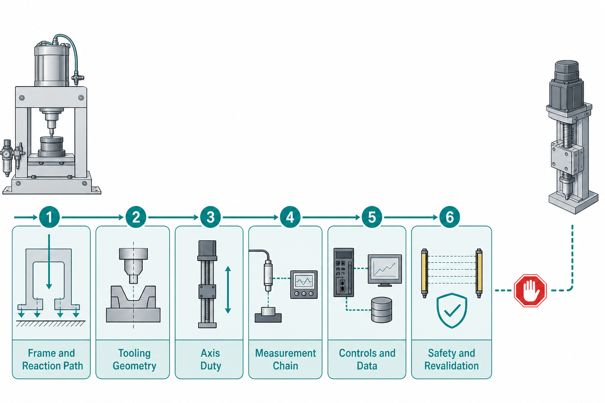
After utilities and lifecycle cost are normalized, replacing a cylinder with a servo axis still is not a component swap until the machine proves it can accept the new loads, geometry, controls, and safety functions. Treat the project as a machine modification and reopen the joint-validation plan.
The 6-Gate Pneumatic-to-Servo Retrofit Screen
| Gate | Evidence required | Hidden failure if skipped | Decision owner |
|---|---|---|---|
| 1. Frame and reaction path | Rated load path, deflection, fatigue, mounting, and engineering approval | A controlled axis on a frame that moves or is overloaded | Machine builder / mechanical engineer |
| 2. Tooling geometry | Shut height, alignment, access, punch/die support, and service envelope | Side load, collision, or a changed material-flow path | Tooling + manufacturing engineer |
| 3. Axis duty | Force-motion profile, cycle rate, dwell, thermal duty, screw/bearing life | A peak-force match that misses duty life | Drive supplier / machine builder |
| 4. Measurement chain | Sensor location, range, uncertainty, calibration, and data retention | A precise-looking curve that does not measure the joint load accurately | QA + controls |
| 5. Controls and data | PLC interface, recipes, access rights, backups, alarms, part identification | Uncontrolled parameter changes or orphaned quality records | Controls + IT/OT |
| 6. Safety and revalidation | Risk assessment, safety functions, validation, new sample and acceptance plan | Old safeguards applied to a different motion and control architecture | Safety team + QA |
Stop the retrofit concept when the frame margin, tool alignment, guarding concept, sensor path, or revalidation owner is unknown. A new axis can add control capability, but it cannot repair missing machine evidence.
If the application may need a different equipment architecture rather than a drive swap, compare the wider clinching machine paths. Requirements that extend beyond clinching-specific equipment can also be reviewed against servo press systems.
Safety and Control Architecture Are Machine-Level Decisions
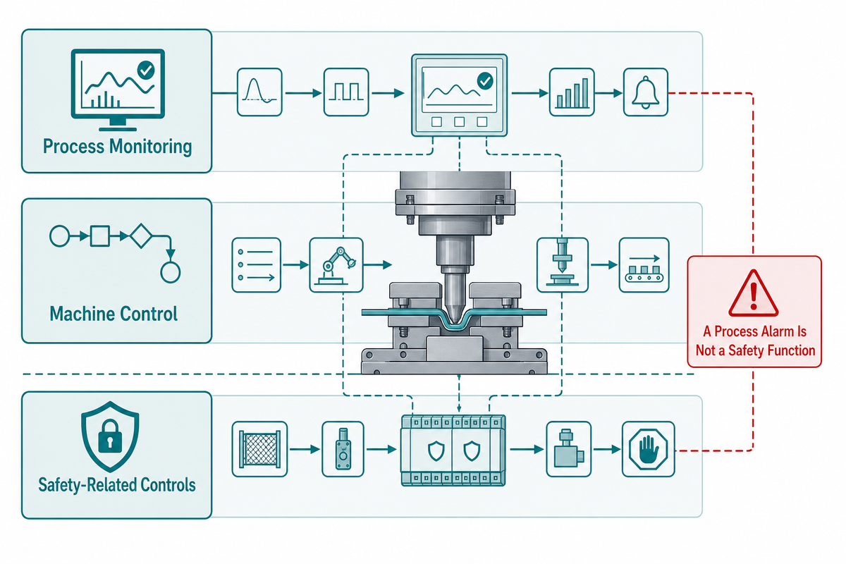
ISO 12100:2010, Edition 1 and confirmed in 2022, provides general principles and a method for machinery risk assessment and risk reduction. ISO 13849-1:2023, Edition 4, addresses the design and integration of safety-related parts of control systems. Neither reference chooses the safety functions or required performance level for a particular clinching cell, and citing a standard isn’t evidence that a machine complies.
For U.S. workplaces, OSHA 29 CFR 1910.212 requires guarding where point-of-operation and other machine hazards expose employees to injury. Other jurisdictions and machine applications have their own requirements. Final concepts must be assessed for the installation, modes, users, material handling, and foreseeable intervention.
Separate the functions
- Process monitoring judges the joining cycle.
- Safety-related controls perform defined risk-reduction functions.
- Machine control coordinates production.
Do not assume
- A process alarm is a safety function.
- A two-hand control is always sufficient.
- A servo stop automatically satisfies the risk assessment.
When a drive or control system changes, review operating modes, point-of-operation access, stored energy, unexpected restart, maintenance access, safe setup, tooling change, loading, unloading, and fault recovery. Validate each selected safety function as part of the machine, not as a product-name feature.
The Hidden Bottleneck Map: Where a Drive Decision Really Fails
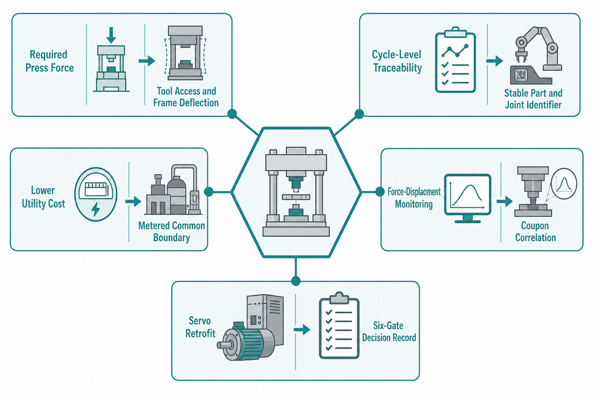
Beyond the machine-level safety functions, a press proposal can look complete while the project risk sits outside the actuator. This map makes the hidden constraint and its owner visible before price comparison; clinching integrity research is one reason the evidence chain must extend beyond nominal actuator force.
| Visible requirement | Hidden bottleneck | Consequence | Owner and proof |
|---|---|---|---|
| Required press force | Tool access, reaction path, and frame deflection | Nominal force is available but the joint location cannot be supported | Plant/mechanical: part and fixture review |
| Cycle-level traceability | No stable part/joint identifier or data-retention rule | Curves are collected but cannot support containment or audit | QA + IT/OT: record architecture |
| Lower utility cost | Quotes use different system boundaries and reject assumptions | Payback is a comparison of unlike scopes | Finance/facilities: metered common boundary |
| Fast changeovers | Tooling, fixtures, recipes, and approval are not linked | A saved recipe does not prevent the wrong physical setup | Production + QA: controlled changeover proof |
| Force-displacement monitoring | No coupon correlation or measurement-uncertainty review | A clean curve creates false confidence | QA: correlation and revalidation report |
| Servo retrofit | Existing frame, safety, or maintenance evidence is incomplete | The actuator is purchased before the machine concept is valid | Owner + machine builder: six-gate decision record |
Procurement can now compare equal scope: the drive, tooling, sensors, controls, data, safety, validation, training, spares, and service boundary. Finance can calculate cost per accepted joint rather than purchase price alone. QA can refuse a monitoring claim without a correlation plan. Plant managers can identify whether access, handling, or maintenance, rather than the actuator, is the actual capacity constraint.
Turn the Comparison into a Testable Project Decision
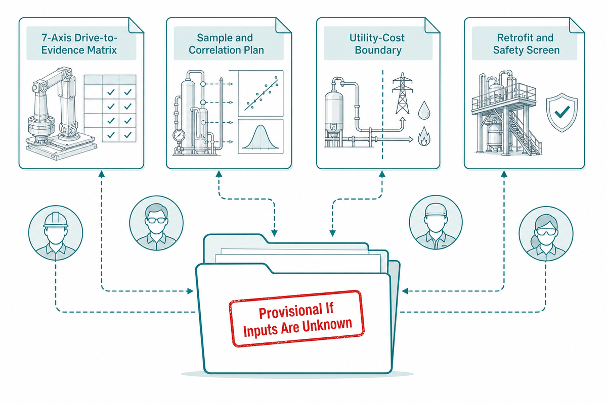
A defensible handoff contains four attached records: the completed 7-Axis Drive-to-Evidence Matrix, a sample and correlation plan, the agreed utility-cost boundary, and the result of the retrofit and safety screen. If a joint, tooling, access, or safety input remains unknown, label the drive recommendation provisional. In the Plant Delta case, that means the trial inputs stay provisional until the same records close the decision.
Engineering decision rule: choose the drive after the joint, process-evidence, utility, retrofit, and safety obligations are visible—not from the actuator label alone.
Minimum decision record
- Production material grades, sheet order, thicknesses, coatings, and accepted variation ranges.
- Joint locations, access space envelopes, fixture or support concepts, and service loads.
- Recipe identifiers, cycle-record requirements, audit logs, and restart authority.
- Measured utility boundary, expected accepted-joint output, maintenance scope, and reject cost.
- Sample-test methods, signal-to-joint correlation, periodic checks, and revalidation triggers.
- Machine risk assessment, selected safety functions, and validation responsibility.
Use the solution Page for available configurations and an application-specific engineering review. This guide doesn’t publish a model recommendation because the required evidence can’t be inferred from the focus keyword alone.
Suzhou Simitch Machinery Co., Ltd. describes its clinching and precision-pressing focus on the About SIMITCH page. Company experience, patents, certifications, market reach, and customer figures remain first-party statements unless separately verified.
Frequently Asked Questions
The project handoff above turns the remaining buyer questions into checks against the same joint, utility, safety, and evidence boundary.
Does a servo press automatically make a stronger clinched joint?
No. Servo control can change motion and process evidence, but joint strength still depends on the material stack, tooling, geometry, setup, and validation—not on drive type alone.
Servo axes may control position, speed, or force-related functions more closely than a simpler air circuit, but that capability does not create an approved neck thickness or interlock by itself. Section joints and perform the mechanical or functional tests required by the real load case. Use the curve to monitor the validated process, not to replace physical proof. Keep material certificates, tool identity, sample orientation, settings, test method, and acceptance result beside the curve so later production records retain a physical reference.
Can pneumatic clinching points be checked with process monitoring?
Yes. Sensors can be configured around a pneumatic or pneumohydraulic process, provided the signal is meaningful, correlated with accepted joints, and governed by a defined control plan.
Available signals may include pressure, force, position, stroke, and cycle timing, depending on the machine. Monitoring plans should state sensor range and location, correlation method, limits, alarm response, and revalidation triggers. Do not assume that adding a sensor gives the same control behavior or record quality as an integrated servo joining system. First confirm that the existing frame, tool alignment, control platform, and data interface can support a repeatable measurement chain.
What data should a force-displacement record include?
Keep enough data to identify the part and joint, interpret the curve, and connect the cycle to the controlled recipe, acceptance window, and later revalidation decisions.
Useful records can include time, part and joint identifier, recipe revision, force and displacement samples, selected curve features, result, alarm code, and equipment status. Required sampling rate, units, retention, access control, and export format depend on the application and quality system. Preserve the metadata needed to compare records after maintenance or process changes, and document how the record links back to released coupons.
Can a servo press replace an existing pneumatic or pneumohydraulic axis?
Sometimes, but only after the machine passes the frame, tooling, duty, measurement, controls, and safety gates using the real production stack and documented decision owners.
Matching peak force is not enough. Check reaction loads, deflection, mounting, shut height, alignment, cycle duty, screw and bearing life, sensor path, interfaces, risk assessment, and joint revalidation. Price the conversion against a complete replacement with the same scope.
How often should a servo press measurement chain be calibrated?
There is no universal interval for every press, sensor, and application. Set it from risk, duty, history, governing requirements, and documented trigger events for recheck.
Set the interval from the manufacturer’s instructions, the plant quality system, measurement risk, duty, environment, history, and customer requirements. Recheck after overload, repair, sensor replacement, or unexplained drift. Cover the complete measurement chain used for acceptance, not only one component certificate.
Which evidence should move from sample trials into production monitoring?
Carry forward the approved material and tooling conditions, joint-test results, correlated signal features, limits, alarm response, revalidation triggers, responsible owner, and retention rule for production records.
Production records should show that the released recipe and physical setup remain in control. Keep the link between coupons, curves, tools, material lots, maintenance, and changes. If that link is lost, the signal’s quality meaning becomes uncertain.
Review the evidence before choosing the drive
Bring material stacks, joint definitions, required cycle conditions, production needs, power boundary, and acceptance criteria to the discussion. When all such factors are presented together, a comparison of real applications becomes possible, moving beyond simple label matches.
How this guide was prepared
We separated drive capability, process evidence, joint acceptance, and machine safety so each claim can be checked against the right source. The technical boundaries were checked against peer-reviewed clinching research, servo-system documentation, ISO machinery-safety scopes, and the U.S. machine-guarding baseline. SIMITCH product-family and quotation information remains on the linked solution Page.
References & Sources
- Ensuring the integrity in clinching process Journal of Materials Processing Technology
- Optimization of Clinching Joint Process with Preforming between Ultra-High-Strength Steel and Aluminum Alloy Sheets Metals, 2024
- Servo presses: definition, advantages and applications Kistler
- ISO 12100:2010, Safety of machinery International Organization for Standardization
- ISO 13849-1:2023, Safety-related parts of control systems International Organization for Standardization
- 29 CFR 1910.212, General requirements for all machines Occupational Safety and Health Administration