Get in touch with Suzhou Simitch Machinery Co., Ltd Company

ISO Certified
Clinching Machines & Equipment
Clinching Machines & Equipment for Sheet Metal Assembly
A SIMITCH clinching machine forms a sheet-metal joint without an added fastener or welding heat. Your right path—portable tool, production press, or application-built equipment—still depends on the actual material stack, access, load case, production duty, and handling scope.
Parent-category guidance only: equipment-family images, model parameters, and detailed specifications remain on the linked category pages.
Request a Quote for Your Part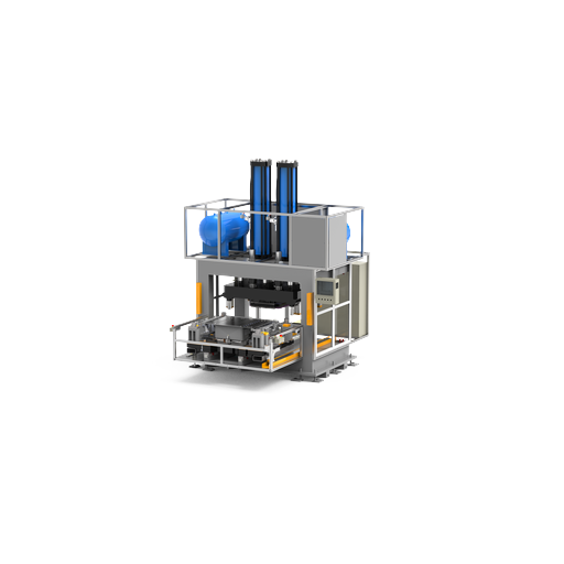
3 paths
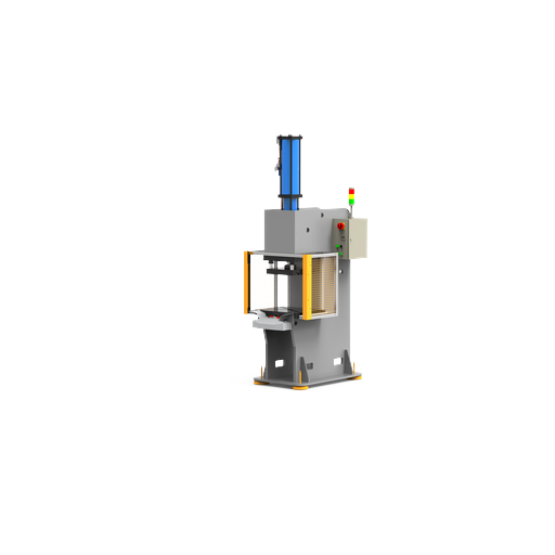
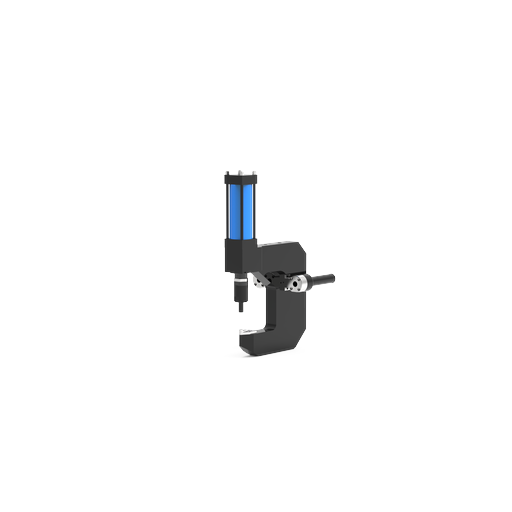
Portable, press, or application-built
8 gates
Part-to-architecture decision ladder
Since 2006
Sheet-metal connection machinery focus
Sample-led
Feasibility and acceptance planning
Match the Clinching Process to the Part—Not Just the Machine
A sheet metal clincher does not become suitable because its catalog category looks right. Material ductility, sheet order, coating condition, formed geometry, tool access, and the way the joint will be loaded can change both the joint design and the equipment architecture.[1]
Evidence boundary: These selection variables follow the peer-reviewed review of clinching for sheet materials; feasibility still needs confirmation on the production stack.
01 / Material Stack
Use the production material, not a convenient substitute
- Identify whether the stack uses mild steel, another steel grade, aluminum, or a mixed material combination; then record coating, gauge or thickness, sheet order, and any adhesive or surface layer.
- State whether the sheets arrive flat, bent, drawn, embossed, or otherwise pre-strained.
- Flag cosmetic surfaces and any coating damage that would be unacceptable.
02 / Load and Service
Define what the joint must survive
- Separate tensile-shear, peel or cross-tension, cyclic, vibration, and application-functional requirements.
- Describe temperature, moisture, corrosion, and visible-side constraints.
- Agree which load direction and failure mode are relevant to acceptance.
03 / Physical Access
Check the real flange and reaction path
- Map punch-side and die-side access at every joint location.
- Provide the surrounding envelope, throat restriction, nearby bends, and fixture obstruction.
- Confirm how joining force will be reacted without distorting the part or overloading the operator.
04 / Production Duty
Size the operating method around the work
- Share takt, shifts, daily volume, variant count, changeover frequency, and batch pattern.
- Explain who presents the part and whether the part, tool, or both must move.
- State any controls, traceability, guarding, and line-interface expectations.
An Honest Force Trade-off
More joining force is not always the correct fix; the wrong tool geometry, access path, or reaction structure can still create a quality and rework risk because the whole joint system acts together. Simitch will not claim fit from a catalog category alone, so a drawing and representative material remain the starting evidence.
Engineering Boundary
Clinching creates a mechanical interlock without an added rivet or screw, but “no welding heat” does not mean “no material risk.” Plastic deformation can still affect coatings, and a joint qualified in one loading direction does not automatically cover another service condition.[1]
“We do not start with the press catalog. We start with the material stack, the joint location, the load direction, and the evidence the buyer will use to accept production.”
Simitch Application Engineering TeamWhy Force Alone is Not a Selection Rule
Joining force matters, but it sits inside a larger system. Tool geometry, alignment, reaction stiffness, blank holding, part support, and the material’s formed condition influence whether a repeatable interlock can be produced.
What Reliable Manufacturing Starts With
- A dimensioned part drawing or 3D file with proposed joint locations.
- The actual sheet stack, material order, coating, and formed condition.
- The relevant load directions, service exposure, and acceptance method.
- Volume, takt, variants, operator handling, utilities, and line-interface limits.
Three Clinching Equipment Paths from Portable Tools to Production Systems
SIMITCH groups its clinching equipment around three buying paths. These cards route you to the relevant child category; final tooling, joint quality, and machine configuration remain subject to part-specific review.
Evidence Boundary: The published process review documents both portable equipment and press-based execution; the actual part and acceptance plan decide whether either route is feasible.
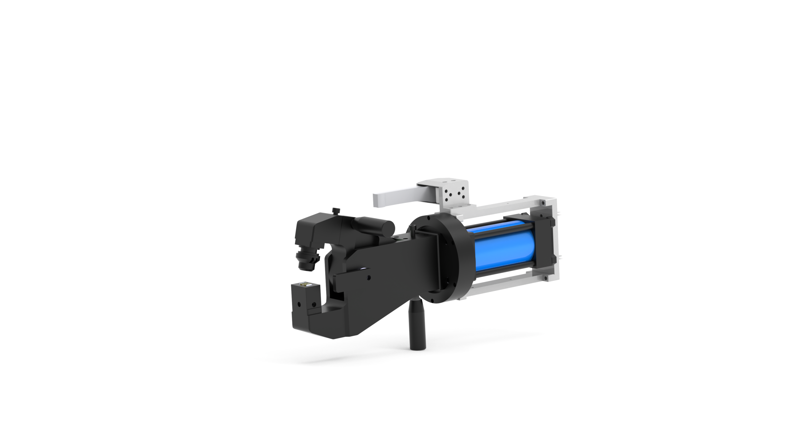
Path A
Portable & Handheld Clinching Machines
Consider a portable clinching machine when the part stays in place and moving the tool is operationally preferable. The feasibility check still covers required force and reaction, access, tool support, operator handling, and the available pneumatic, hydraulic, or electrical utility.
- Field or station movement is a real project constraint.
- The joint locations can be reached with a workable tool envelope.
- Tool mass, suspension, reaction, and operator exposure can be managed.
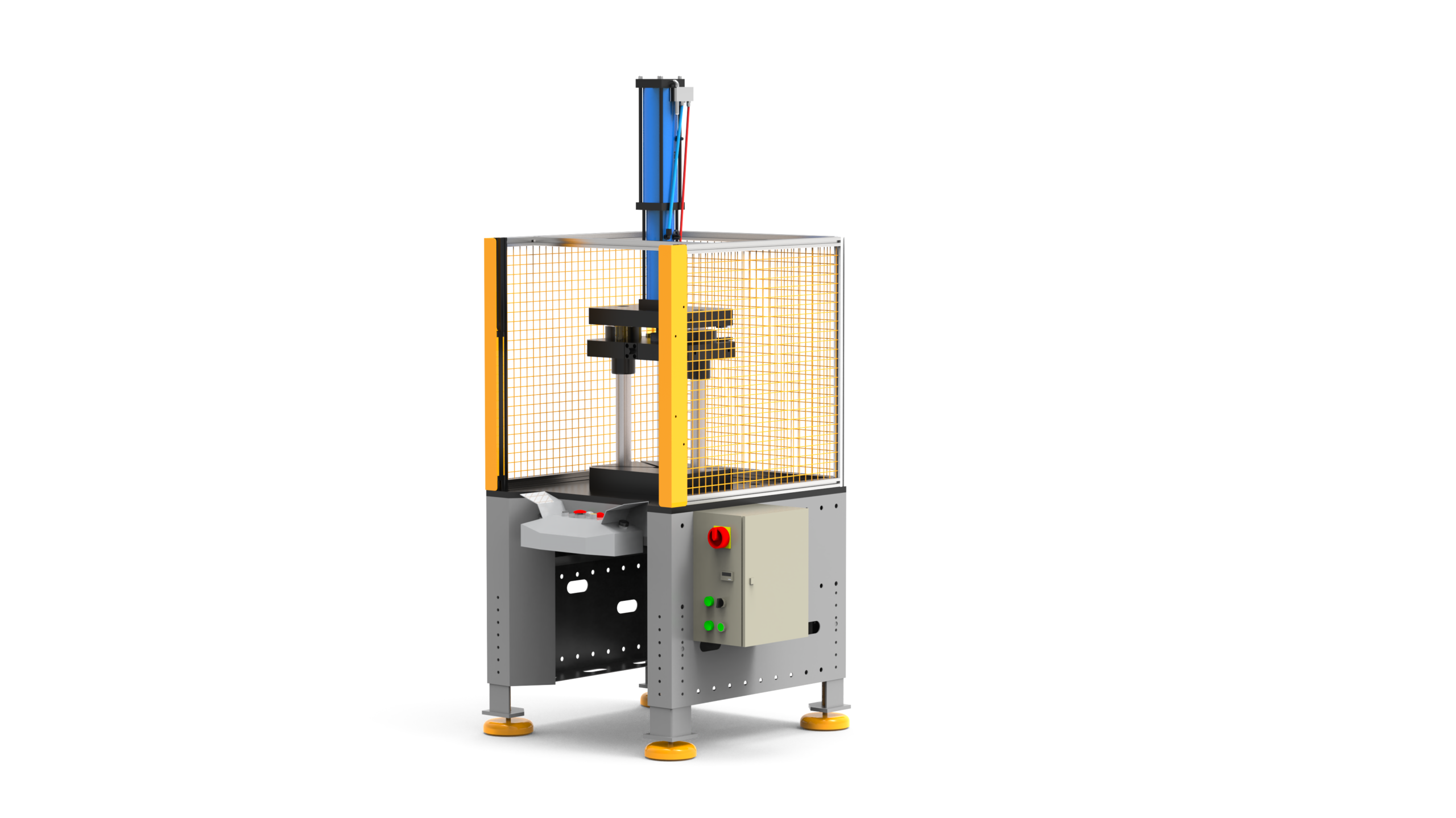
Path B
Pneumatic & Servo Clinching Presses
Choose a press path when the application needs a stable tool relationship, defined part presentation, controlled operation, or a clear process-monitoring baseline. Pneumatic and servo are drive choices to evaluate, not automatic proof of greater strength, speed, or precision.
- The part can be presented to a fixed or guided clinching press.
- Fixture, tool alignment, and repeatable cycling matter to production.
- Monitoring, controls, and changeover need a defined machine boundary.
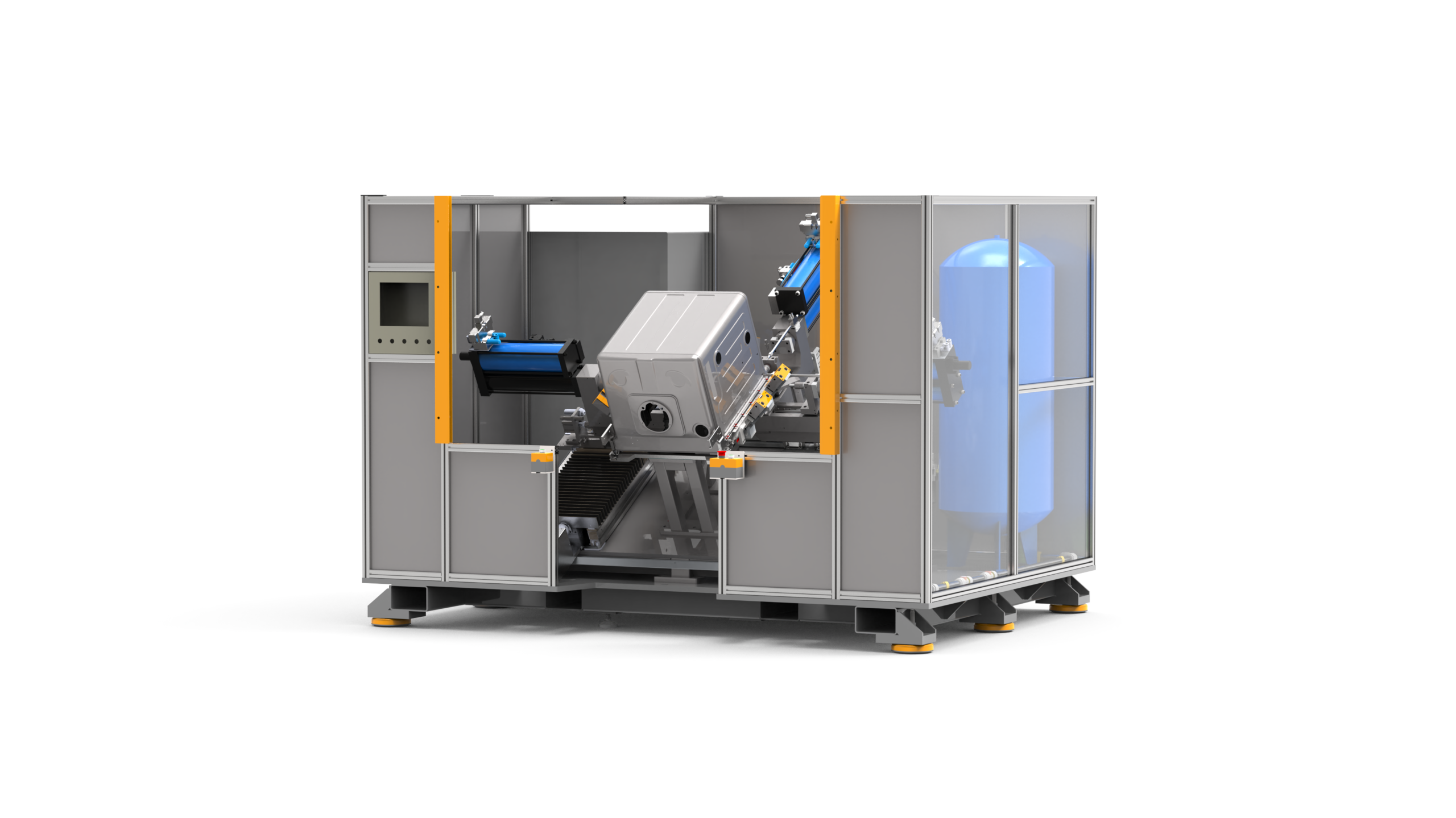
Path C
HVAC & Home Appliance Assembly Systems
Use the application-built route when joint pattern, part geometry, handling, fixtures, controls, and integration dictate the process. Here, a sheet metal clinching machine is one part of a larger production solution.
- Multiple joints, part fixturing, and indexed work shape a more involved cycle.
- HVAC or appliance geometry requires application-specific access.
- Define the machine, fixture, safeguarding, controls, and site connections as one scope.
The 8-Gate Clinching Configuration Decision Ladder
SIMITCH organizes the RFQ and project-acceptance questions in this ladder format. It supports a responsible quote for a portable tool, press, or application-built system, but it does not replace a joint-specific qualification plan.
Material and Joinability
Record the actual alloy or grade, coating, thickness stack, sheet order, ductility, and formed condition. A sample made from a different flat coupon may not represent a drawn or coated production part.
Load and Service
Define tensile-shear, peel or cross-tension, cyclic or functional duty, load direction, and the temperature, moisture, corrosion, or coating exposure that matters.
Force and Access
Evaluate required joining force, reaction structure, flange direction, tool envelope, throat restriction, cosmetic side, and every intended joint location.
Tool and Joint Geometry
Develop the punch-and-die concept, joint spacing, target geometric evidence, and the failure-mode criteria that will be examined during trials.
Production Duty
Connect takt, shifts, daily volume, variant mix, changeover, handling, and ergonomic support to the operating architecture.
Monitoring and Maintenance
Agree process signals, sampling frequency, tooling-condition checks, tool-wear limits, maintenance access, and the response to production drift.
Architecture and Integration
Select portable tool, production press, fixture, or integrated system; then define utilities, controls, handling, guarding, and line-interface boundaries.
Acceptance and Commercial Scope
State sample tests, measurable acceptance criteria, machine and tooling scope, documents, FAT/SAT, training, spares, and site responsibilities.
A Practical Routing Rule
Choose the least complex design that can pass the verified acceptance process and production-duty criteria. Extra complexity can increase project cost without resolving the underlying joint risk.
| Decision Input | Portable / Handheld Route | Production Press Route | Application-Built Route |
|---|---|---|---|
| What Moves | Tool moves to a part that is difficult or undesirable to move | Part is presented to a fixed or guided tool set | Part, fixture, tooling, or handling move in a coordinated sequence |
| Access Basis | Each joint fits the portable tool and reaction envelope | Joint fits the press throat, die-side support, and fixture relationship | Access is engineered around part geometry and joint pattern |
| Production Definition | Operator method, support, utility, and repeatability are agreed | Cycle, fixture, control, and changeover boundary are agreed | Handling, controls, guarding, interfaces, and acceptance are co-designed |
| Information Location | Images and parameters on the portable/handheld child page | Images and parameters on the pneumatic/servo press child page | Images and parameters on the HVAC/appliance child page |
Clinching vs Spot Welding and Riveting—Decision Boundaries
Clinching, resistance spot welding, and riveting solve different assembly problems. Compare them against actual material properties, access, joint duty, visible- and hidden-side requirements, factory utilities, and acceptance evidence.
Evidence boundary: Process claims in this comparison follow the peer-reviewed clinching review, which also records material, geometry, load-mode, fatigue, corrosion, and monitoring limitations.

| Decision Condition | Clinching | Resistance Spot Welding | Riveting |
|---|---|---|---|
| Added Fastener At Each Joint | No separate fastener is introduced by the clinching operation | No separate fastener is introduced by the weld | One rivet or rivet body is introduced at each joint |
| Local Joining Heat | Joint is formed by plastic deformation without welding heat | Electrical resistance produces local heat to form the weld | Depends on rivet process; the fastener is mechanically installed |
| Material And Coating Question | Verify ductility, coating response, stack order, and formed condition | Verify weldability, coating/electrode behavior, heat effect, and electrical contact | Verify hole or self-piercing behavior, fastener compatibility, and corrosion couple |
| Joint Access | Punch and die access plus a workable reaction path are required | Electrode access and clamping path are required | Tool access depends on the selected rivet and installation method |
| Visible-Side Result | Evaluate button/projection direction and cosmetic-side acceptance on the real part | Evaluate electrode marks, indentation, and heat-related appearance | Evaluate fastener head, tail, hole, or self-piercing appearance |
| Acceptance Evidence | Agree geometry, load tests, functional tests, process signals, and sampling | Agree nugget or weld evidence, load tests, electrical/process signals, and sampling | Agree setting evidence, fastener condition, load tests, and inspection |
| Maintenance Boundary | Punch/die condition, alignment, lubrication if specified, and drift response | Electrode condition, cooling, power delivery, alignment, and weld monitoring | Fastener supply, nose/tool condition, feed system, and installation monitoring |
| Correct Decision | Verify on the actual part against the same load, service, production, quality, and commercial scope. | ||
An Honest Process Comparison Without the Sales Shortcut
A familiar process is not always the lowest-risk option for the actual part. SIMITCH brings each comparison back to the same load, service, production-duty, maintenance, and acceptance conditions regardless of process choice.
Where Clinching Reaches a Boundary
Some applications still need joint performance at a welding-equivalent level. Going without an added fastener does not establish fatigue, corrosion, or environmental durability. The Fabricator’s overview also ties method choice to material, access, and strength rather than a universal ranking. [4]
Compare Equal Scope Before Comparing Cost
Process economics vary with scope and supplier responsibility. A quote covering tooling, fixtures, controls, safeguards, testing, and commissioning is not directly comparable to one covering only the machine. Clarify scope and acceptance duty before analyzing price and projected operating cost.
Sample Validation, Tooling and Production Acceptance
A credible clinching machine supplier should provide evidence for a performance claim before asking for acceptance. SIMITCH uses part information, sample work, tooling data, and the agreed acceptance plan to narrow the gap between a satisfactory trial and stable production.
Evidence boundary: The public scope of DVS 3420 covers component design, process design, quality assurance, and testing, while applicable guarding duties must be checked against the relevant OSHA machine-guarding standards.
Step 1
Application intake
Drawing, material stack, sheet order, formed condition, joint locations, load directions, service exposure, volume, and takt.
Step 2
Feasibility review
Tool access, joining-force reaction, part support, tool concept, equipment path, utilities, and operator or automation method.
Step 3
Trial plan
Representative samples, proposed joint locations, tooling setup, measurable joint criteria, and the load or functional tests the buyer will review.
Step 4
Production controls
Process signals, inspection sampling, punch-and-die condition, wear checks, maintenance access, and response to drift.
Step 5
Scope separation
Machine, tooling, fixture, handling, utilities, controls, guarding, documentation, and site-interface responsibilities.
Step 6
Acceptance handoff
FAT/SAT boundaries, training, maintenance documents, spares, open items, and the evidence required before sign-off.
Acceptance criteria should follow the joint’s real duty
A visual check does not answer every performance question. A visually acceptable joint is not always a qualified production joint. Depending on the application, the plan may require tensile-shear, peel or cross-tension, cyclic, functional, coating, corrosion, temperature, or environmental evidence under an agreed sampling plan.
Standards and guarding scope
DVS 3420 (04/2021) identifies component design, process design, quality assurance, and testing within its clinching-basics scope.[2] For U.S. installations, OSHA’s machine-guarding resources provide general point-of-operation requirements, while the precise rules that apply depend on the machine classification and site installation.[3]
Company development without inflated proof
2006 — Mechanical equipment foundation
Suzhou Simitch Machinery Co., Ltd. began as a traditional mechanical equipment manufacturer focused on sheet-metal connection machinery.
Early development — Technology introduction
Early work introduced foreign clinching technology and built production and application experience in the equipment category.
Ongoing development — Independent R&D
SIMITCH reports a progression from technology introduction to independent research, development, and innovation in clinching and precision pressing.
Current capability boundary
The company reports independent trademarks, multiple technical patents, and independent production of key equipment and core parts. Patent numbers, certification marks, customer counts, and performance metrics are not stated here because they were not supplied for public verification.
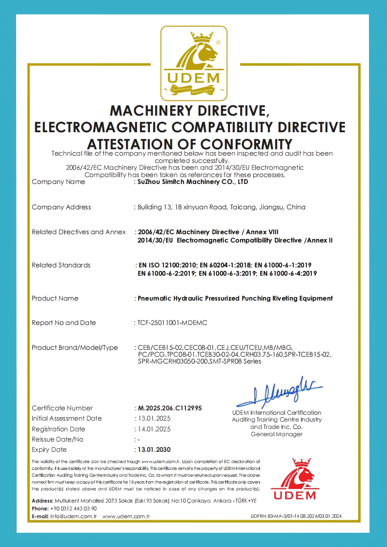
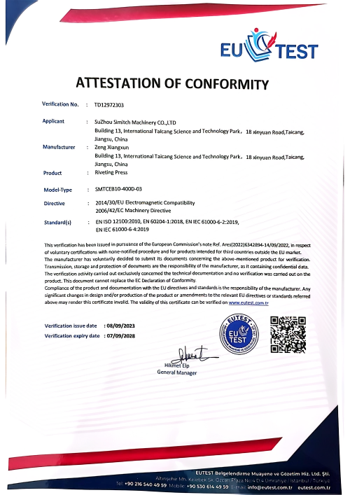
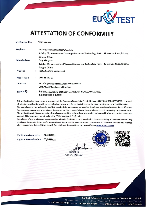
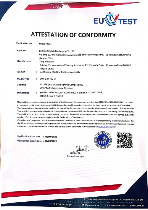
Established 2006
Bounded company-history claim
Part-First Review
Actual stack and geometry requested
Acceptance Defined
Evidence agreed before sign-off
Independent R&D
Technology-development capability
Core-Part Production
Reported internal production scope
×
![Enlarged View]()
Clinching Equipment & Engineering Tools
Clinching Equipment Path Selector
Describe the production constraint first. The selector returns a provisional equipment-category path and the questions that still need sample validation.
Access Tool ➔Comparable Clinching RFQ Brief Builder
Capture the same ten engineering inputs for every supplier. A complete brief helps separate a comparable quotation from a price that quietly assumes a different joint, reach, control scope, or acceptance test.
Access Tool ➔Cost per Accepted Joint Comparison
Compare two joining options with your own period costs and first-pass yield. The worksheet contains no preset price, labor rate, utility cost, scrap value, production rate, or savings assumption.
Access Tool ➔FAQ for Clinching Machine Selection and Quotation
Start with the actual material stack, formed geometry, load case, access, required reaction, joint pattern, takt, handling, and acceptance evidence. A portable tool fits a different operating problem from a fixed production press, while an application-built system is appropriate when fixture, handling, controls, and joint sequence govern the design. Use the 8-Gate Decision Ladder before treating any equipment family as final. If two paths remain plausible, define one representative trial and compare them against the same joint evidence, operator method, production duty, utilities, maintenance boundary, and commercial scope. Final routing follows the part and acceptance plan, not the category label.
Send a drawing or 3D model, the material grade or alloy, coating, thickness or gauge of each sheet, sheet order, and the real formed condition. Mark proposed joint locations, punch and die access, cosmetic surfaces, load directions, service exposure, and any nearby bends or obstructions. Production volume, takt, variants, utilities, and operator or automation expectations help SIMITCH assess the equipment path.
A handheld clinching tool is worth evaluating when the part should remain in place and moving the sheet metal clinching tool is practical. Mobility alone is not enough: joining force, reaction structure, throat and flange access, tool mass, suspension, operator exposure, and utility supply must work together. Suitable portable equipment can be a normal production choice after those conditions are demonstrated.
Quotation scope depends on more than the drive or frame. Material and part definition, tool concept, fixture and handling, controls, guarding, utilities, validation tests, FAT/SAT, documentation, training, spares, delivery destination, and site responsibility can all change the supplied scope. A complete RFQ makes competing offers easier to compare and reduces hidden exclusions. Ask each supplier to identify included items, optional items, exclusions, assumptions, and the evidence covered by the price. When one offer includes production tooling and acceptance work while another covers only a press, normalize those differences before treating the headline amounts as comparable.
Compare all three methods against the same materials, load and service duty, production volume, access, cosmetic requirement, quality evidence, maintenance boundary, and commercial scope. Clinching avoids an added fastener and welding heat, but still requires two-sided tool access, material deformation, tooling, and part-specific qualification. Spot welding and riveting have their own access, consumable, heat, fastener, monitoring, and maintenance conditions.
Integration is possible when responsibilities are defined around the real line. The RFQ should identify part transfer, fixtures, sensors, controls interface, data and traceability, guarding, utilities, maintenance access, cycle states, fault recovery, and who owns each connection. SIMITCH should review those interfaces before the machine and site acceptance scope is fixed.
Acceptance should state the representative parts, material condition, joint locations, measurable joint evidence, relevant load or functional tests, process signals, sampling, and tool-condition checks. FAT and SAT should also separate supplier and site responsibilities, utilities, guarding status, documentation, training, open items, and the rule for closing deviations. The exact plan depends on the machine classification, application risk, and buyer requirements.
This parent page intentionally avoids product images, model specifications, and parameter tables. Visit the pages for portable and handheld clinching machines, pneumatic and servo clinching presses, or HVAC and home appliance clinching systems for family-specific content.