Get in touch with Suzhou Simitch Machinery Co., Ltd Company

Servo Riveting Assembly Systems Built Around the Actual Joint
SIMITCH servo riveting assembly systems feature an 80 kN power unit, your choice of SPR gun and C-frame, automated rivet feeding and detection, and integration to your production line. Equipment boundaries are quantified and your specific application is validated for cycle, interface, guarding and joint-acceptance.
Send Your Joint and Layout for Review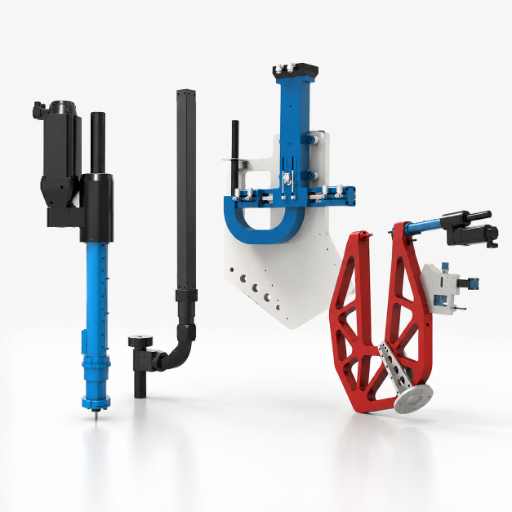
Specifications
80 kN
Maximum riveting force
200 mm
Effective stroke
0–333 mm/s
Speed range
SPR
Feed and detection scope
When the Joint Needs More Than an Automatic Riveting Machine
A single-point, high force riveting head is a solution for only one piece of an automated riveting project. Part stack, access approach, rivet feeding path, process decisions, and the overall assembly line need to work together.
The first failure pattern to remove
A C-frame can meet an 80 kN force envelope and still fail at the joint because the die side is blocked by the automotive fixture. Unlike selecting only a head, SIMITCH uses the trade-off between access, feed and production risk to build the review around the complete assembly.
Request a detailed joint-and-layout review.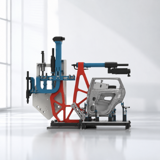
Material grade, thickness, coating, lubrication condition and stack order affect rivet and die selection. A total thickness alone doesn’t describe crack or interlock risk.
Throat, opening, approach direction and fixture clearance decide whether the punch and die can reach the joint. Larger frames also change stiffness, weight and service access.
Magazine, tube, gun head and rivet family must be planned together. A late rivet-size change can turn into a hardware change, not a software recipe.
Force, displacement, position and detection signals can screen process variation. They don’t remove the need for agreed joint checks on the validated material stack.
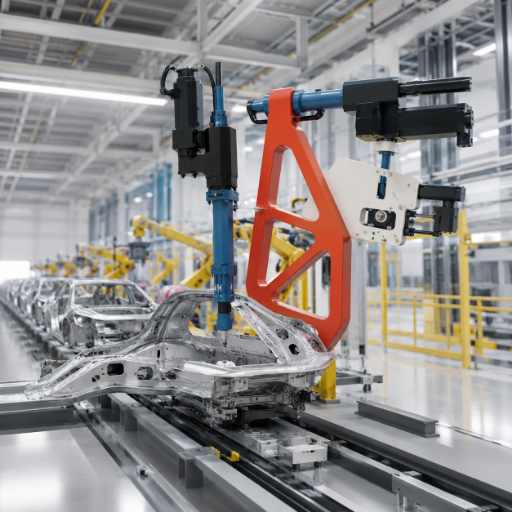
Fixture control, robot motion, line signals, guarding and commissioning records belong to the integrated cell. Their final scope is project-specific.
- Force, stroke, speed and positioning values shown in supplied product material.
- Dual-row magazine, presence and process checks, anti-flip and centering functions.
- C-frame throat, opening and mounting ranges documented by SIMITCH.
- Cycle target, robot and PLC protocol, data fields and alarm actions.
- Fixture, feed distance, changeover, guarding and service-access plan.
- Cross-section, appearance and mechanical joint-acceptance criteria.
This page covers self-piercing riveting for industrial and automotive assembly. Orbital riveting, blind-rivet fastening and other joining families require a different tooling and acceptance review. An NIH-hosted SPR study illustrates why rivet geometry and sheet-stack order remain process-specific inputs.
- A common assumption is that process monitoring proves joint strength; it screens variation but doesn’t replace the acceptance plan.
- Higher setting force is not always the fix when the rivet, die or stack order is wrong.
- Robot reach is not always usable access when the die side, feeder tube or service zone is blocked.
SIMITCH 80 kN Servo Riveting System Components
A complete system is assembled from a servo-driven power unit, an application-specific SPR gun and frame, a gun-head set, a rivet feeder and the required controls. These modules are selected against the joint and the cell rather than sold as an isolated catalog head.
- Servo-driven riveting power unit
- Multi-specification SPR gun and C-frame family
- Gun-head and delivery components
- Dual-row automatic rivet feeding system
Why module fit matters
Choosing the wrong gun or feed route can cause rework because an 80 kN power unit doesn’t define the rivet, die or fixture. SIMITCH engineers the system around the application, whereas a catalog comparison can hide the trade-off between stroke, frame weight and service access.
Capability is layered
The power unit supplies controlled motion and riveting force. Gun, frame, rivet path, feeder and project control determine whether that capability can be used at the real joint location. An open-access joint study hosted by NIH supports the separate boundary between machine configuration and stack-dependent joint behavior.
Verified item
Value shown in supplied product data
Engineering meaning
Maximum riveting force
80 kN
Power-unit capacity; required setting force still comes from sample validation.
Effective stroke
200 mm
Available motion envelope before tooling and part geometry are checked.
Speed range
0–333 mm/s
Programmable motion range; no universal cycle result is claimed.
Pressure accuracy
±2%
Equipment-control value shown by the manufacturer, not a joint-strength tolerance.
Repeat positioning accuracy
0.01 mm
Positioning value shown in product data; the complete joint variation includes more inputs.
Servo motor options shown
Rexroth / Lenze
Brands displayed in supplied material; final procurement configuration requires confirmation.
Rivet magazine
Two rows; 35 rivets per row; 70 total
Magazine capacity before refill and cycle planning are agreed.
Maintenance references
Minor service at 1M cycles; major service at 3M cycles
Manufacturer references that require an operating-condition and service-plan review.
Rated service-life reference
At least 6 million cycles
Manufacturer-rated value, not a warranty or site-specific uptime guarantee.
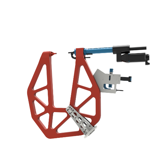
Use the Rivet Path-to-Access Fit Matrix
This six-input matrix exposes configuration conflicts before quotation. It’s useful for a servo riveting machine, a robot-mounted SPR gun or a stationary assembly cell because each architecture still depends on the same physical rivet path.
Fit before force
A robot-mounted gun can reach a coordinate and still fail because a 200 mm opening doesn’t clear the fixture or the die-side path. SIMITCH confirms against the layout; unlike a larger-is-better rule, the right call balances reach, stiffness, payload and feed-tube risk.
Send your drawing for a custom access review.| Input | What to provide | System decision | Risk surfaced early |
|---|---|---|---|
| Joint stack | Grades, thicknesses, coatings, lubrication, stack order and forming direction | Rivet and die family, trial plan and inspection scope | Cracks, incomplete interlock or excessive remaining-sheet reduction |
| Rivet family | Diameter, length, head form and material | Magazine, tube, head and gun-nose configuration | Wrong-rivet or incompatible feed hardware |
| Access envelope | Joint coordinates, throat, opening, approach and fixture clearance | C-frame geometry and mounting position | A reachable robot pose with an unreachable die side |
| Cell architecture | Stationary, robot-mounted or floor-standing concept | Frame weight, stiffness, reach, support and integration scope | Payload, inertia, foundation or maintenance-zone conflict |
| Feed path | Distance, angle, bend route, refill and changeover plan | Magazine angle, tube route and service access | Feed instability or production entry for refill |
| Quality decision | Signals, records, sample checks and mechanical acceptance method | Detection, process control and production response | A process alarm mistaken for a proven joint result |
One rivet family per feed setup
SIMITCH’s supplied product data states that 3 mm and 5 mm rivets can’t be mixed in one magazine configuration because the feeder head, tube and gun-head setup differ. Treat a rivet-family change as a tooling and feed-path decision. For the joint-side boundary, an NIH-hosted SPR study shows why rivet geometry and stack order cannot be reduced to machine force alone.
Standard throat options
SIMITCH material shows C-frame throat selections from 100 to 600 mm. Choose the shortest workable path that also clears the fixture and service zone.
Robot-mounted range
Lightweight robot-mounted frame options are shown above 600 mm and up to 900 mm. Robot payload, inertia, cable and rivet-tube routing remain project inputs.
Floor-standing reach
Floor-standing throat depth can reach 1500 mm in the supplied range. Foundation, stiffness, part handling and operator access must be reviewed with the layout.
Include joint coordinates, approach direction and the nearest fixture obstructions.
Send Layout for Review →Select the Drive and Cell Architecture Against the Process Window
Servo, hydraulic and simpler actuation choices should be compared against the required motion profile, monitoring, access and maintenance plan. This page doesn’t assume that a servo architecture produces the best financial result in every application.
Make the comparison scope visible
A low equipment price can become expensive rework because tooling, integration, trials and service are outside the quoted boundary. SIMITCH won’t claim a universal return; the honest trade-off compares the same 80 kN application, production pattern and acceptance scope.
Request a detailed scope-aligned quotation.| Decision dimension | Question to resolve | Evidence needed before release |
|---|---|---|
| Force, position and speed | Does the joint need programmable stages or a simpler fixed action? | Sample curve, motion limits and joint results on the actual stack |
| Process monitoring | Which signal screens a deviation, and what separate check accepts the joint? | Process-window method plus cross-section or mechanical plan |
| Feed and changeover | How many rivet families, refills and hardware changes are expected? | Magazine, tube, head and changeover definition |
| Cell access | Will a stationary frame, robot end effector or floor stand reach every joint? | Robot and fixture layout with service zones |
| Maintenance | Who owns lubrication, wear parts, access and planned service? | Operating conditions, spare list and responsibility matrix |
| Cost boundary | Which tooling, integration, trials and commissioning items are inside the quote? | Scope-aligned commercial comparison |
Cost-driver card, not a universal payback claim
- Power unit, gun, frame and tooling configuration.
- Rivet feeder, refill route and changeover hardware.
- Fixture, robot, PLC, safety and line-interface scope.
- Sample trials, sectioning, mechanical tests and acceptance records.
- Spare parts, planned service, training and site support boundary.
Compare like-for-like production scope
A pneumatic or hydraulic alternative may suit a simpler joint, while a servo architecture can support programmable motion and process monitoring. Productivity and energy efficiency still depend on the complete cycle, including part loading, conveyor or robot transfer, feeding, changeover and reject handling.
Why the page stays at a Bronze evidence level
Independent cost guidance separates equipment and operating inputs but uses dated values and emphasizes customization. A current price, savings percentage or payback must come from a comparable project scope, so the page publishes decision factors only. For robot-cell scope, OSHA guidance keeps safeguarding and risk assessment inside the integration decision rather than a headline machine-price comparison.
Build Feed, Presence and Process Detection Into the Cell
SIMITCH system data shows a dual-row feeder, rivet-in-place detection, rivet-process detection, anti-flip and centering functions. These capabilities address different failure points and shouldn’t be collapsed into one “quality control” claim.
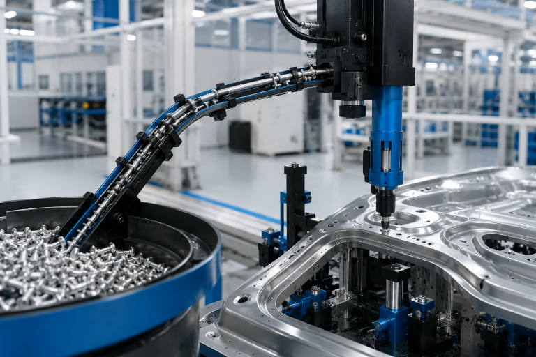
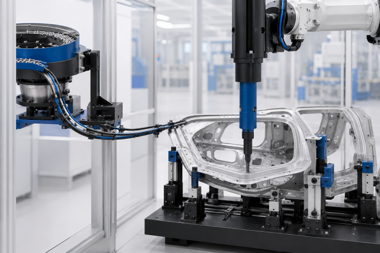
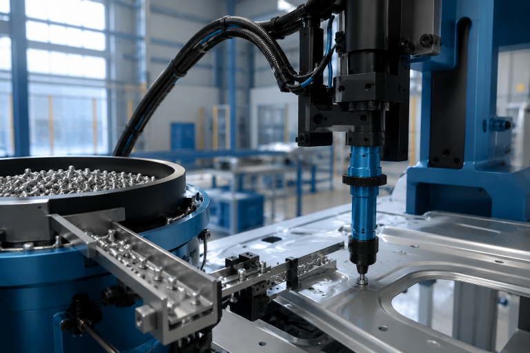
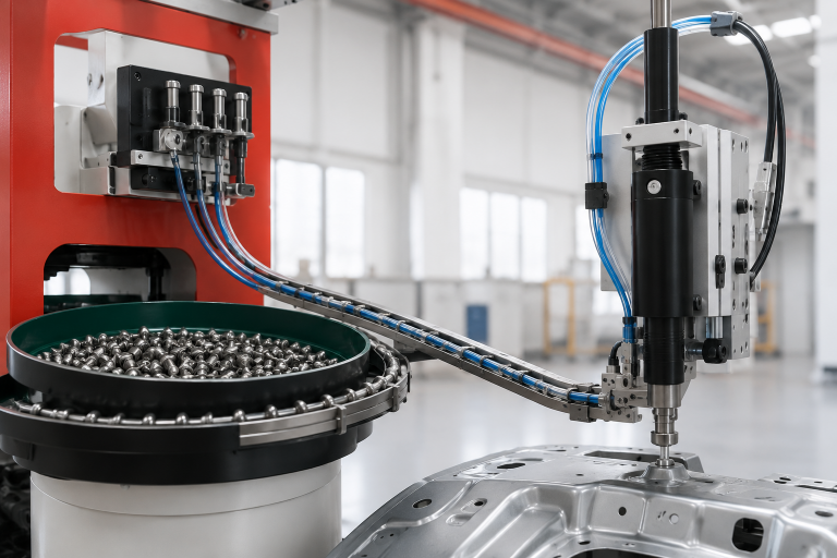
Feed hardware must match the rivet family, gun head and route.
Match Stationary, Robot-Mounted and Floor-Standing Configurations
Frame architecture determines how the part, rivet and die come together. It also changes payload, support, service access, guarding and commissioning work.
Reach can create a new constraint
A deeper frame may solve access and introduce payload, deflection or guarding risk because the 900 mm robot-mounted envelope moves with the end effector. SIMITCH confirms against the production layout; unlike a comparison based only on throat depth, the trade-off includes fixture, routing and commissioning.
Request a custom stationary-versus-robot review.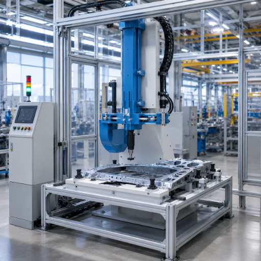
Stationary riveting cell
The part or fixture moves into a fixed gun and frame. Confirm opening, throat, part loading, fixture reaction and access for wear-part service.
- Useful when the joint path fits a stable station.
- Reduces moving end-effector mass.
- Requires a defined part-handling sequence.
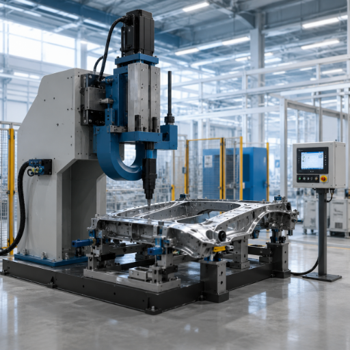
Robot-mounted lightweight frame
A robot moves the riveting end effector to the joints. Confirm payload, inertia, reach, hose route, collision envelope and recovery position before the layout is approved.
- Useful for distributed joint locations.
- Expands work-envelope planning.
- Adds robot and end-effector risk controls.
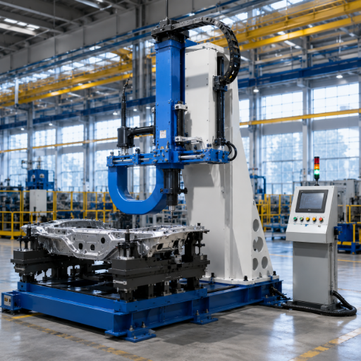
Floor-standing deep-throat frame
A supported frame reaches farther into a large part or fixture. Confirm foundation, stiffness, deflection, operator access and material handling around the 1500 mm maximum shown in the supplied range.
- Useful for deep access without robot payload.
- Requires floor and support planning.
- Must preserve tooling and die-side service access.
| Constraint | Stationary | Robot-mounted | Floor-standing |
|---|---|---|---|
| Part movement | Part or fixture moves to the gun | Gun moves to the part | Part is positioned within deep frame access |
| Primary load concern | Fixture and station reaction | Robot payload and inertia | Frame support, stiffness and foundation |
| Routing concern | Feed and service access at a fixed station | Moving cables, rivet tube and collision envelope | Long access path and operator/material flow |
| Safety scope | Pinch point and part-transfer controls | Robot system risk assessment and safeguarding | Pinch point, handling and fixed-machine guarding |
Robot reach is not a commissioning approval
OSHA treats the end effector, controls, power and sensors as part of the robot system and calls for risk assessment before commissioning. The integrator must define safeguarding, interlocks, failure states, responsibility and validation records for the completed cell.
Validate the Joint Before the Production Build
A self-piercing rivet joint is created by the interaction of material, rivet, die, stack order and process. Sample trials turn those variables into a measurable acceptance plan before production tooling and controls are frozen.
Catalog values cannot close the joint risk
A sample can crack or lose interlock because rivet height, die geometry and stack order change deformation even when the machine reaches 80 kN. SIMITCH builds the resolution around agreed acceptance criteria; unlike a process-signal shortcut, the right call pairs production monitoring with section or test evidence.
Review the parts
Record material grades, thicknesses, coatings, lubrication, stack order, joint coordinates and access direction.
Define the system
Select the power unit, rivet and die family, gun, C-frame, feed path and station architecture.
Run sample trials
Produce joints with the proposed stack and tooling while recording the process conditions.
Agree acceptance
Set the section, appearance, measurement and mechanical test criteria required for the application.
Freeze the build
Release tooling, control, fixture, guarding and commissioning inputs after evidence is reviewed.
Why SIMITCH for a Project-Specific Riveting System
Suzhou Simitch Machinery Co., Ltd. was established in 2006 as a sheet-metal connection machinery manufacturer. Its history describes a progression from introduced clinching technology to independent research, precision pressing capability and internal production of key equipment and core parts.
Trust without overclaiming
An unfamiliar supplier creates verification risk because buyers can’t infer project delivery from a product rendering or 2006 establishment date. A public trademark record lists SIMITCH registration number 6303415 to Suzhou Simitch Machinery Co., Ltd.; certification, individual patent and performance claims still stay qualified until the relevant records are reviewed.
Request a specific capability and evidence review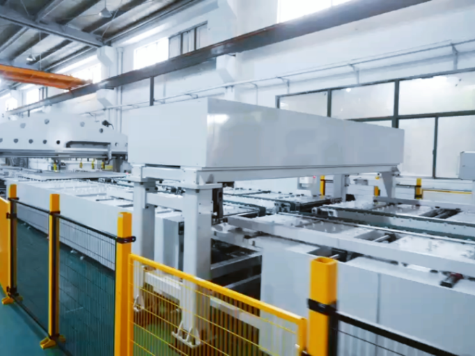
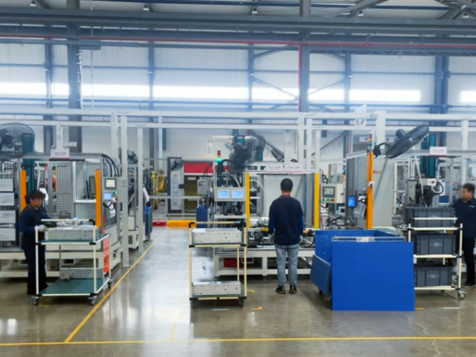
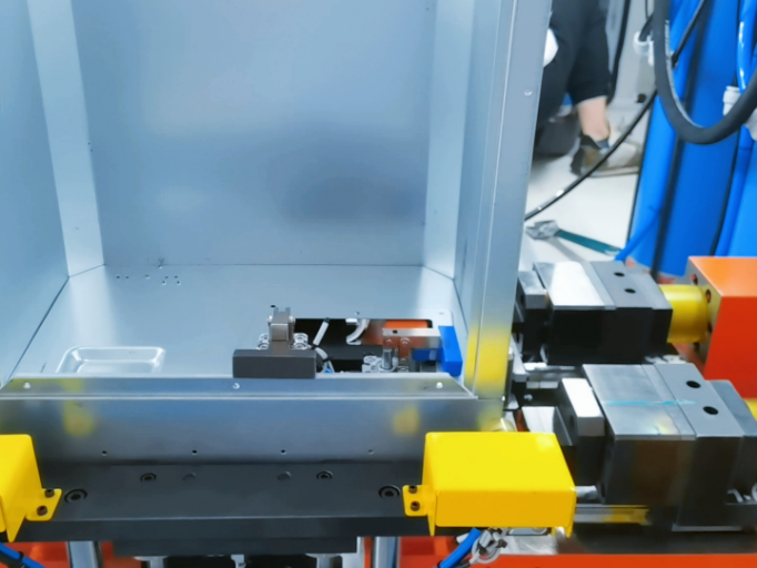
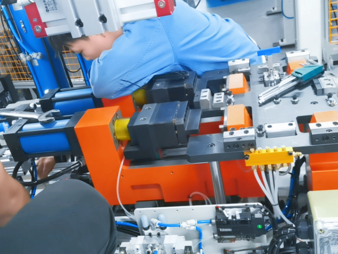
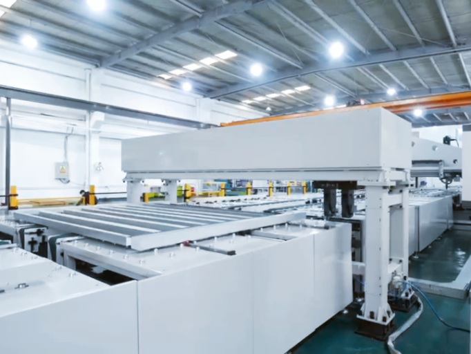
SIMITCH began with mechanical equipment for sheet-metal connection applications.
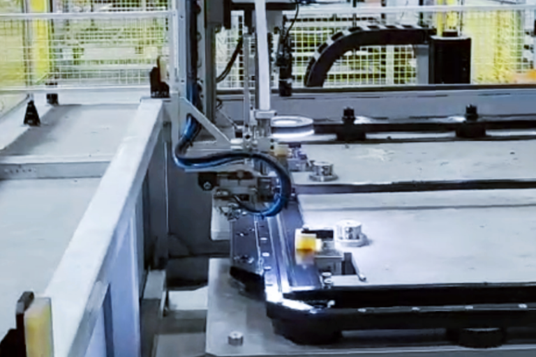
Early clinching technology introduction supported practical equipment production and application work.
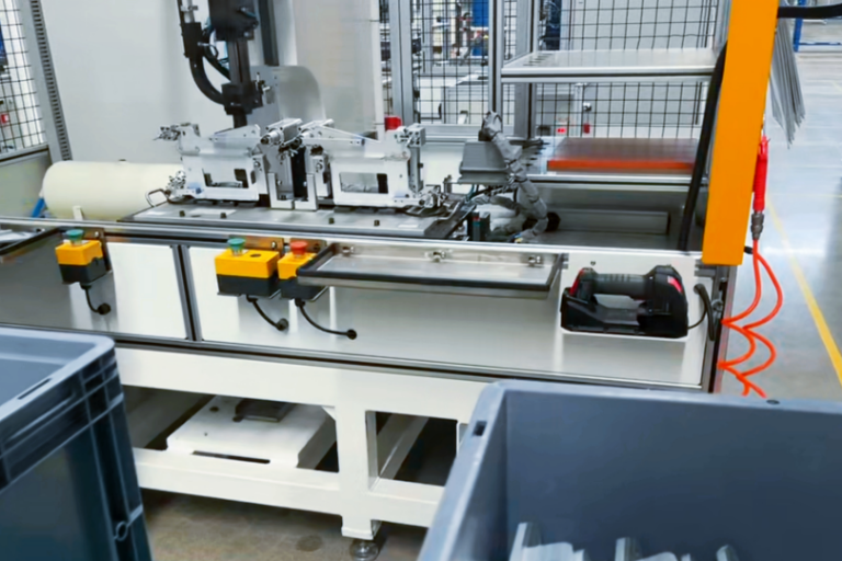
The company reports development from technology adoption to independent research and innovation, including servo riveting technology.
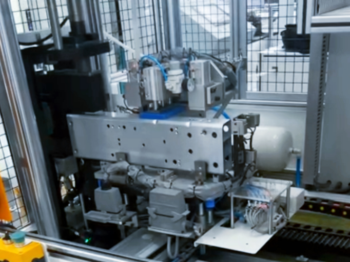
SIMITCH reports independent production of key equipment and core parts, plus its own trademarks and technical patents.
Statements used on this page
- Establishment year and development history supplied by the company.
- Visible product configuration and parameter data.
- Public trademark record plus OSHA robot-system guidance for the integration and safety boundary.
Claims held for project confirmation
- Patent numbers, certification scope and customer installation counts.
- Specific PLC, robot, network and data-interface protocol.
- Cycle time, joint strength, delivery, warranty and financial result.
Related assembly solution
Applications that need controlled pressing without a self-piercing rivet may require a different process architecture. Review SIMITCH servo press systems for battery pack and electronics assembly before choosing the joining route.
FAQ: Servo Riveting Assembly Systems
These answers distinguish verified equipment data from decisions that depend on the part, rivet, layout and acceptance plan.
A project may combine the servo power unit, SPR gun and C-frame, gun head, automatic rivet feeder, detection functions, tooling, controls and the selected station interfaces. Final supply scope is defined in the quotation.
Use joint coordinates, approach direction, fixture clearance, die-side access, part loading and the service zone. SIMITCH data shows 100–600 mm standard throat options, lightweight robot-mounted options above 600 mm and up to 900 mm, and floor-standing depth up to 1500 mm.
No mixed 3 mm and 5 mm setup is shown in the supplied product data. The feeder head, tube and gun-head configuration differ, so the rivet family must be defined before the feed hardware is released.
Use a stationary arrangement when the part can be presented reliably to a fixed gun. Use robot mounting when distributed joints need a moving end effector and the robot can satisfy payload, inertia, routing, safeguarding and access requirements.
The supplied material shows rivet-process detection, rivet-in-place detection, anti-flip and centering functions. The final alarm logic, reject action, record fields and line interface are project-specific.
A force-displacement window can screen process variation, but the signal may not correlate precisely with the joint’s mechanical properties. The validated plan may also require cross-section geometry, appearance and mechanical tests.
Published SPR research uses indicators such as head height, interlock or deformed-rivet geometry, bottom thickness and minimum remaining thickness. Exact criteria and measurement methods must be set for the actual material stack and loading requirement.
Provide part drawings, materials and stack order, rivet data, joint positions, access envelope, station concept, feed route, cycle target, interface needs and acceptance requirements. More complete inputs reduce configuration assumptions.
The supplied data references minor service at 1 million cycles and major service at 3 million cycles, with a rated life reference of at least 6 million cycles. Operating conditions, lubrication, wear parts and the commercial service commitment still need project confirmation.
The page treats those interfaces as project-defined inputs because the supplied material doesn’t establish one universal protocol set. Share the controller, signal, alarm, data and network requirements for review.
No universal cycle-time or payback result is claimed on this page. Both depend on the part, rivet, motion path, feeding, changeover, integration scope, operating pattern and acceptance method.
Compare the verified equipment envelope, rivet and die scope, access method, feeder, detection layers, sample-validation plan, interface boundary, service access and commissioning responsibility. A headline force or cycle claim doesn’t define the same supply scope.
The press or power unit supplies force and controlled motion. A complete cell also resolves the gun and frame, tooling, feed route, fixture, part handling, controls, safeguarding and acceptance method.
The review should cover end-effector mass and inertia, robot reach, cable and rivet-tube routing, fixture collision, failure states, safeguarding, interlocks and commissioning evidence. The robot model and cell layout are needed before those boundaries can be confirmed.