Get in touch with Suzhou Simitch Machinery Co., Ltd Company

Servo Press Systems for Precision Assembly and Line Integration
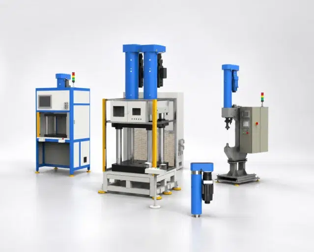
Servo press systems from Simitch combine programmable motion, force-displacement evidence, and system-level engineering for assembly cells that must prove every press cycle. Its BP platform covers 10–200 kN with a standard maximum stroke of 300 mm, while project engineering connects the press to tooling, safety, traceability, and production-line interfaces.
10–200 kN
BP rated-force range
300 mm
Standard max stroke
0.01 mm
Repeat positioning
10 kHz
Force/displacement sampling
>500,000
Stated service-life cycles
100,000
Process records
Turn an Unstable Pressing Task into a Controlled Assembly Process
Tonnage alone does not describe how a servo press delivers force. A 60 kN requirement can still fail when part tolerance, lubrication, ram alignment, fixture deflection, or contact speed shifts the force-displacement curve outside the accepted window.
Control what creates the joint
- Set approach, contact, press, and return speed by process stage.
- Monitor press force and final position against up to four evaluation windows.
- Record curve evidence for quality control, troubleshooting, and release decisions.
- Use external force or displacement sensors when the measurement point must move closer to the part.
- Provide precise control of force and position at every stage of the press cycle.
Press-fit force calculations can miss surface finish, temperature and lubrication effects; sample parts are still needed. Simitch engineers use the real part, tooling concept, and acceptance criteria to define the servo motor, linear motion, load cell, and control system as one press system.
Start with your difficult part
Send a drawing, target force, available stroke, and one good/bad sample definition. That submission is enough to identify the missing proof-out inputs before you commit to a machine layout.
Get the Sample-Test Checklist“A credible precision assembly press project starts with the accepted joint and works backward to force, motion, sensing, tooling, and line handshakes. The catalog model is one layer, not the whole answer.”— Simitch Engineering Team
Choose the Right Simitch Servo Press Platform
Programming is intimidating when a team moves from pneumatic or hydraulic presses. Selection stays practical here by separating the press module from the complete station scope, then matching each to the application risk.
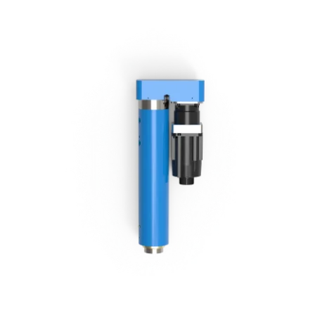
Precision Assembly Press, BP Bending-Type Series
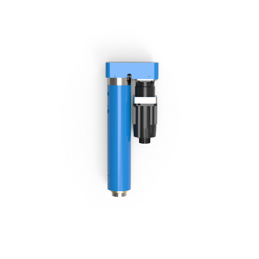
The BP series places the drive beside the press axis, which can help when overhead space, robot access, or station packaging creates a layout problem. Six rated-force choices cover 10, 30, 60, 100, 150, and 200 kN.
- Standard maximum stroke: 300 mm
- Repeat positioning: 0.01 mm
- Force-measurement accuracy: 1%
- Rated voltage: 380 V
- Ambient operating range: 0–40°C
- Noise: below 75 dB
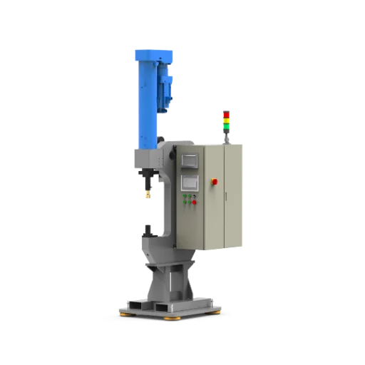
Servo Press for Battery Pack and Electronics Assembly
This solution branch covers cells such as battery-box servo riveting, automatic nut feeding, beam-panel joining, and M8 riveting. Supplied application images prove project scope, but they do not establish a universal compression limit, cycle time, or electrical-test result.
- Define the part support and allowed compression before force settings.
- Correlate curve windows with insulation or functional checks where required.
- Link every record to the part identifier and rejection route.
- Confirm tooling access, fastener feeding, robot handling, and safety boundaries.
Representative BP Series Specifications for Early Sizing
The wrong model creates two risks: insufficient force at the real working position, or an oversized measurement range that hides small process changes. Early sizing starts with the table below, then duty cycle, off-axis load, tooling mass, and the force profile get confirmed before the final selection.
| Model | Rated force | Maximum speed | Standard max stroke | Motor power | Early-fit use |
|---|---|---|---|---|---|
| SMT-BP-10-300 | 10 kN | 300 mm/s | 300 mm | 1.5 kW | Small parts, electronics, light insertion |
| SMT-BP-30-300 | 30 kN | 200 mm/s | 300 mm | 1.5 kW | Bushings, pins, compact press-fit work |
| SMT-BP-60-300 | 60 kN | 200 mm/s | 300 mm | 3 kW | Automotive component assembly |
| SMT-BP-100-300 | 100 kN | 160 mm/s | 300 mm | 4.4 kW | Higher-load assembly and joining |
| SMT-BP-150-300 | 150 kN | 110 mm/s | 300 mm | 4.4 kW | Large fixtures and slower high-force work |
| SMT-BP-200-300 | 200 kN | 140 mm/s | 300 mm | 7.5 kW | Heavy assembly within verified load limits |
Selection boundary
The model name is not a release decision. Side load, frame stiffness, peak-versus-continuous duty, work height, tooling stack, load-cell range, and the real force curve must be checked because a mismatch can damage the part or make quality data less useful.
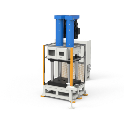
Unlike a catalog-only servo press manufacturer, Simitch can scope the press machine together with the fixture, guarding, sensors, robot exchange, and production data path. That trade-off means a quote-ready project needs more inputs than force and stroke alone.
Check the fit before layout freeze
Ask for an early-sizing review with the force curve or sample parts. The response will identify the candidate model and the missing station-level decisions.
Build Per-Cycle Quality Evidence with Force-Displacement Data
A final force value can look acceptable while the curve contains a slip, burr, wrong part, incomplete seat, or tooling problem. Force and displacement are recorded together here through continuous process monitoring, so a real-time decision can use the path of the press cycle, not one endpoint.
Measurement and evaluation
- One force channel and one displacement channel
- Support for external force and displacement sensors
- Sampling frequency up to 10 kHz
- Low-pass filtering from 0.1 to 2,000 Hz
- Up to four evaluation windows
Storage and factory exchange
- Up to 5,000,000 curve sample points
- Up to 100,000 process records
- Eight digital inputs and eight digital outputs
- PROFINET, EtherNet/IP, EtherCAT, CC-Link, Modbus, and CANopen
- Part result and curve data available for line-level handling
What the curve can help detect
- Contact begins too early or too late because the part is missing, doubled, or misloaded.
- Insertion-slope shifts happen when interference, surface condition, alignment, or lubrication changes.
- Peak force rises as tooling wears or contamination enters the joint.
- Final position fails even though peak press force stayed inside its limit.
An approach speed that stays high through first contact can shock the press or tooling, which is why the approach profile is a set decision, not a fixed default.
The honest version: a 10 kHz acquisition rate will not repair a weak fixture or a bad acceptance window. Reliable quality evidence needs a measured good-part population, defined failure modes, and a change-control rule before that real-time data can be trusted.
Define the Project with the Servo Press Project Definition Stack
A protocol list or a 100 kN rating does not define a production-ready cell. Simitch uses a five-layer stack to expose hidden gaps before they become a late integration delay.
Part and joint result
Material, tolerance, insertion depth, allowed damage, and good/bad acceptance.
Force, stroke, speed, duty
Peak force, working stroke, approach profile, hold step, takt time, and cycles per shift.
Evidence window
Force-displacement limits, sensors, sample rate, record fields, and rejection logic.
Tooling and sensing
Fixture stiffness, ram alignment, part support, load path, poka-yoke, and maintenance access.
Station and line interface
PLC handshake, robot exchange, safety functions, data dictionary, utilities, and acceptance ownership.
This named method is deliberately stricter than “send us tonnage and stroke.” It gives engineering, quality, procurement, and the system integrator one version of the project, which reduces the risk of mismatched assumptions at factory acceptance.
One common assumption that fails
Force-distance monitoring does not always require a servo press; monitoring systems can be added to other press types. Servo control earns its place when the process needs programmable motion, closed-loop response, recipe change, or a defined per-cycle evidence path.
Turn your notes into a quote-ready scope
Use the five layers to gather the missing decisions before suppliers quote different scopes under the same machine name.
The cheapest machine is not always the lowest-risk choice, and the servo option is not automatically the best answer. Motion control, evidence, utility cost, maintenance, and whether the process needs the ram to react to measured force or position drive that decision.
| Decision point | Simitch electric servo press | Pneumatic press | Hydraulic press |
|---|---|---|---|
| Programmed motion variables | Position, speed, and force profile: 3 controlled dimensions | Pressure and stroke endpoints: commonly 2 primary settings | Pressure and stroke endpoints: commonly 2 primary settings |
| Position evidence | 0.01 mm stated repeat positioning (repeatability) on BP models | Requires the selected cylinder, stop, and external measurement package | Requires the selected valve, frame, stop, and measurement package |
| Curve acquisition | Force plus displacement at up to 10 kHz | External monitoring package required | External monitoring package required |
| Stored records | Up to 100,000 process records | Defined by external controller | Defined by external controller |
| Energy evidence | A published 100 kg, 6,000-hour test reported 77% less energy than hydraulic and 90% less than pneumatic | Study comparison only; plant result depends on air system and duty | Study comparison only; plant result depends on pump strategy and duty |
| Best-fit logic | Variable profiles, closed-loop control, recipes, and per-cycle records | Simple repeat motion where air is already available | High-force work where hydraulic characteristics fit the process |
The energy figures above belong to one University of Kassel experiment reported by Assembly Magazine, not to every factory. No fixed saving or payback period is claimed here without a measured baseline, cycle profile, utility rate, and maintenance history.
>500,000
cycles
Silver-level ownership evidence
Use the BP service-life statement as one durability input, then compare measured energy efficiency and energy per cycle, air leakage or oil service, calibration, tooling wear, rework, recordkeeping, and changeover time. This produces a defensible total cost of ownership model without inventing a return percentage.
Compare your real baseline
Share the current press type, cycle profile, utility readings, defects, and maintenance events. This baseline supports a plant-specific comparison without assuming savings.
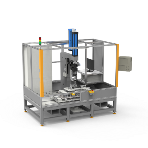
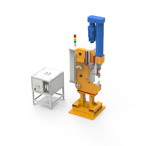
Integrate Tooling, Safety, and Production-Line Interfaces
Network support can still fail at commissioning when signal ownership, safe states, part identity, or rejection handling is ambiguous. PROFINET, EtherNet/IP, EtherCAT, CC-Link, Modbus, and CANopen are treated as available communication paths here, not proof of plug-and-play line acceptance. Controller and supervisory-software configuration is frequently the real integration bottleneck, not protocol choice, since recipe management, user access, and change-control rules still need to be agreed before commissioning.
Mechanical Interface
Controls Interface
System Specs
- Ram-to-tool alignment and allowed side load
- Fixture stiffness and datum strategy
- Part presence, orientation, and support
- Tool change, calibration, and maintenance access
- Press force and speed limits by process stage
- Press operations sequencing with upstream and downstream station cycles
- Robot and PLC handshake sequence
- Recipe, user access, and change-control rules
- Part identifier, result code, curve, and time stamp
- Safe stop, guard, reset, and recovery behavior
- Factory and site acceptance evidence owners
8 + 8 I/O
Digital inputs and outputs for station exchange
6 networks
Protocol options for the selected controls architecture
380 V rating
Regional electrical fit must be confirmed per project
0–40°C
Stated ambient operating range for the BP data set
North American Compliance Note
Review the integration boundary
For a United States plant, the 380 V BP rating also raises a real acceptance question. UL Solutions explains that factory automation equipment and its industrial control-panel portion sit within different requirements under UL 2011/NFPA 79 and UL 508A, so facility voltage, disconnecting means, short-circuit current rating, guarding, and local authority expectations must be agreed before build.
Send the plant standard, PLC family, robot interface, safety concept, and required data fields. That review flags unresolved ownership before the control design starts.
Prove the Process Before Production Release
A press that runs five perfect lab parts can still fail when production tolerances, operator loading, temperature, or lubrication changes. An honest release path uses representative parts, known defects, a frozen program, and measurable acceptance criteria.
Systematic Release Workflow
- Define failure modes: Wrong part, missing part, undersized or oversized fit, incomplete seat, surface damage, and tool wear.
- Build the sample set: Nominal parts, tolerance extremes, known defects, and the real fixture concept.
- Find the process window: Set contact, press, hold, return, and force-displacement evaluation limits.
- Challenge the window: Run repeat cycles, fault insertions, restart recovery, recipe change, and rejection handling.
- Freeze acceptance evidence: Approve the program, curve limits, gauges, records, training, and change-control owner.
For battery or electronic assemblies, this method must also connect the press result to the part’s own compression, insulation, leakage, or functional limits.
Suggested acceptance package
- Approved part and process requirements
- Tooling drawing and load-path review
- Force-displacement window rationale
- Measurement-system and calibration plan
- Factory acceptance and site acceptance test cases
- Backup, recovery, training, and spare-parts handover
Engineering Support and System-Level Delivery from Simitch
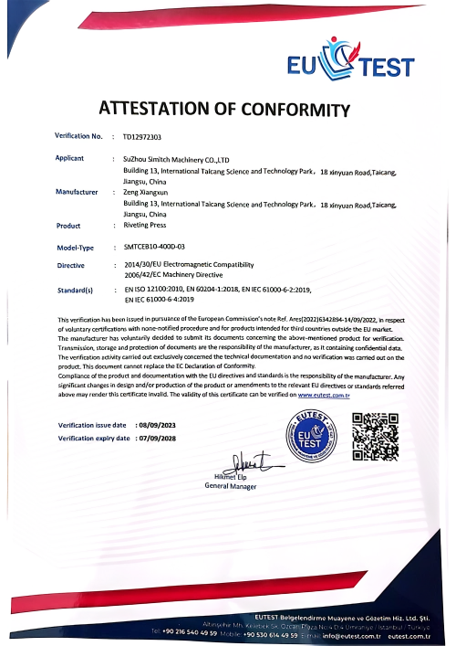
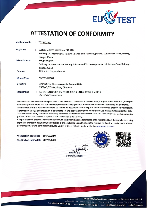
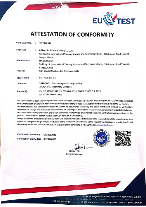
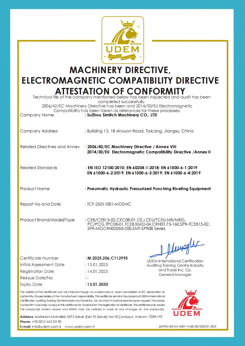
Supplier risk grows when the press vendor, fixture builder, controls team, and line integrator each assume the others own a critical detail. Simitch has worked from Taicang, Jiangsu since September 2006, focusing on intelligent joining equipment and system-level solutions for automotive components, energy-storage batteries, solar photovoltaic, home-appliance, and HVAC production.
Joining equipment depth
- Precision servo pressing systems
- Hydro-pneumatic booster equipment
- Clinching, riveting, SPAC, and self-piercing riveting
- Lightweight sheet-metal joining cells
- Servo press joining module integration for line-level cells
Project-level work
- Application and sample review
- Press, tooling, sensing, and cell definition
- Controls and manufacturing-system interfaces
- Proof-out, acceptance, training, and service planning
The differentiator is not a promise that one platform fits every application. Simitch pairs the precision assembly press with the process and delivery scope, then makes each assumption visible so engineering and procurement can compare like-for-like offers.
What Simitch will not claim
No fixed price, lead time, warranty period, energy saving, or battery-assembly limit is stated here because those values depend on the approved build. A specific proposal should name what is included, excluded, tested, documented, and accepted.
Meet the application team
Bring the part, the current failure, and the line standard. The first discussion can focus on feasibility and risk before a detailed commercial proposal.
Talk to Simitch Engineering
Prepare a Quote-Ready Servo Press RFQ
Price changes when tooling, guarding, measurement, automation, validation, and data scope change. A weak RFQ creates an expensive comparison problem because two suppliers can quote different systems under the same “servo press machine” label.
Part and process inputs
- Part drawings, materials, tolerances, and sample quantity
- Target joint result and allowed cosmetic or functional damage
- Known force, stroke, speed, hold, and takt-time requirements
- Good/bad definitions and current inspection method
- Shift pattern and expected annual cycles
Station and delivery inputs
- Manual, semi-automatic, or robot-loaded concept
- Plant voltage, PLC, networks, and data destination
- Guarding and safety-standard expectations
- Factory/site acceptance, documents, and training
- Shipping destination, installation boundary, and service needs
The trade-off is simple: more scope definition before quotation takes time, but it reduces hidden exclusions and late change orders. Simitch can return a candidate BP model, open questions, proof-out plan, and the system boundaries needed for a useful price comparison.
Bring one real assembly challenge
Share your part drawing, target force or current curve, required stroke, takt time, plant standard, and automation concept. Simitch will use the Servo Press Project Definition Stack to shape a quote-ready precision assembly press solution.
Request a Servo Press QuoteServo Press Engineering Tools
01
BP Servo Press Sizing Calculator
Launch Tool
02
Servo, Pneumatic, or Hydraulic - Which Press Fits Your Process?
Access Guide
03
Compare BP Servo Press Models Side by Side
View Matrix
04
Servo Press RFQ Readiness Checklist
Open Checklist
05
Check Your Plant Network Against BP Servo Press Interfaces
Verify Protocol
Frequently Asked Questions
01
What is the main difference between a servo press and a hydraulic or pneumatic press?
A servo press uses programmable electric motion and can combine position, speed, force control, and force-displacement evidence in one process. Hydraulic and pneumatic presses can still be correct for simpler or force-focused work, especially when closed-loop motion is not required.
02
Does force-displacement monitoring require a servo press?
No. Monitoring can be added to several press types; the servo case becomes stronger when measured feedback must influence ram motion, recipes, changeover, or the release decision.
03
How do I choose the correct tonnage?
Start with sample testing or a reliable force curve, then check peak force, working stroke, speed, duty, side load, tooling, and sensor range. Selecting only by a calculation can miss surface, lubrication, tolerance, and temperature effects.
04
Can the BP series store every press cycle?
Listed controls data states capacity for up to 100,000 process records and 5,000,000 curve sample points. Each project must still define the record fields, retention, export, part identifier, and manufacturing-system interface.
05
Which industrial networks are available?
The listed options are PROFINET, EtherNet/IP, EtherCAT, CC-Link, Modbus, and CANopen. Protocol availability does not replace a signal list, handshake sequence, safety boundary, or data dictionary.
06
Does supporting a common protocol guarantee an easy line integration?
No. Controller and supervisory-software configuration, not protocol selection, is frequently the real integration bottleneck. Recipe management, user access, and change-control rules still need to be agreed before commissioning.
07
Can Simitch quote a battery-pack pressing station from an image?
An image can start the layout discussion, but it cannot define part support, compression limits, electrical tests, or acceptance windows. A sound quote needs drawings, samples, process limits, takt time, traceability, and rejection requirements.
08
Why can a press-fit feel rough even when the final depth is correct?
Alignment, burrs, surface finish, lubrication, interference, approach speed, fixture stiffness, and trapped contamination can change the insertion curve. The curve and the finished-part checks should be reviewed together.
09
What should be included in factory acceptance testing?
Use representative parts and known defects to test programs, curve windows, safety behavior, robot or PLC exchange, data records, restart recovery, changeover, calibration, and rejection handling. The final list should name the evidence and acceptance owner for each test.