Get in touch with Suzhou Simitch Machinery Co., Ltd Company

Simitch Industrial Riveting Equipment for Automated Assembly
Select riveting equipment by joint, access, feed, motion, inspection and production-line scope—not by a force number taken out of context. Our engineers build self-piercing, servo and application-line systems around the part and the evidence your team needs to accept the build.
Discuss Your Riveting Project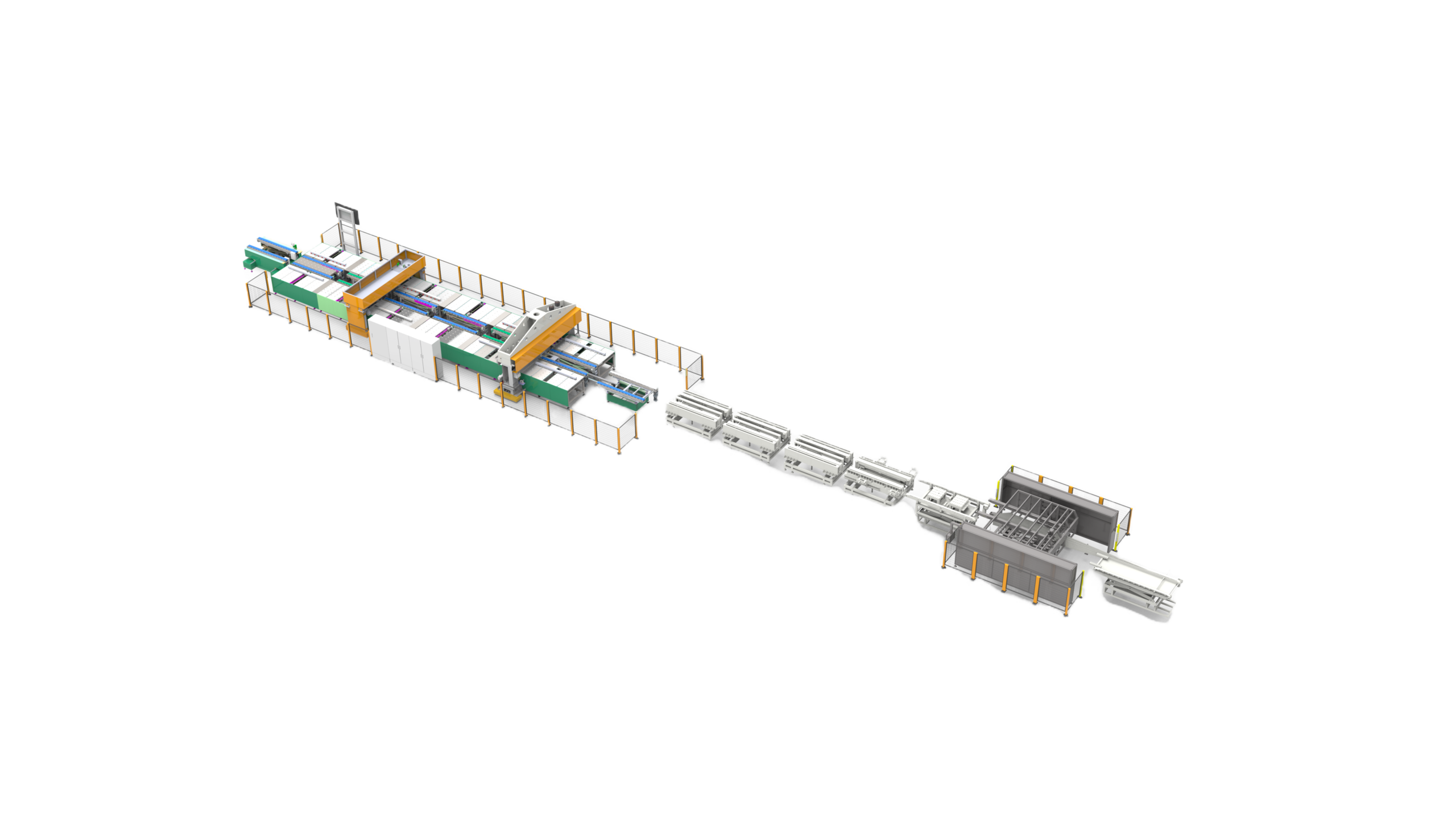
Compare 3 System Types
3 system routes
SPR machines, servo systems, application lines
Up to 80 kN
Named servo power-unit data
Force + position
Configured process evidence
Robot-ready scope
Mounting, controls, safety and acceptance
Turn Riveting Requirements into a Controlled Assembly Process
A riveting machine purchase can fail before the press ever cycles: the material stack is incomplete, the rivet and die are unmatched, access is guessed, or the quote excludes the feed and inspection work. Engineering starts with the finished joint and then binds each decision to a named Simitch machine or cell scope.
Joint
- Material and thickness stack
- Rivet, die and joint geometry
- Appearance and acceptance limits
Access
- Throat and opening
- Gun or frame envelope
- Tool approach and fixture clearance
Process
- Force, stroke, speed and position
- Rivet presence and seating
- Trace, alarm and result storage
Cell
- Feed and changeover
- Robot and PLC handshakes
- Guarding, recovery and handover
Compare 3 Riveting Equipment System Types
The right industrial riveting machine depends on how the fastener is set, how the workpiece is reached, and how much of the surrounding assembly system must be delivered. Every figure below belongs only to the named supplied configuration; no values are combined into a fictional all-in-one model.
Selection evidence before model choice
Begin with a sample stack and joint map, then show the access envelope and expected part presentation. A 50 or 75 kN pneumatic/hydraulic SPR option solves a different problem from an 80 kN programmable servo power unit, while an elevator or rail-transit line adds fixtures, station controls, inspection and handover work that no single press rating can describe.
- Prove the joint with the intended material and rivet
- Check tool access against the fixture and robot path
- Separate machine cycle from finished-station takt
- Confirm which inspection and data functions are in the quote
Self-piercing route
Self-Piercing Riveting SPR Machines
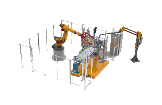
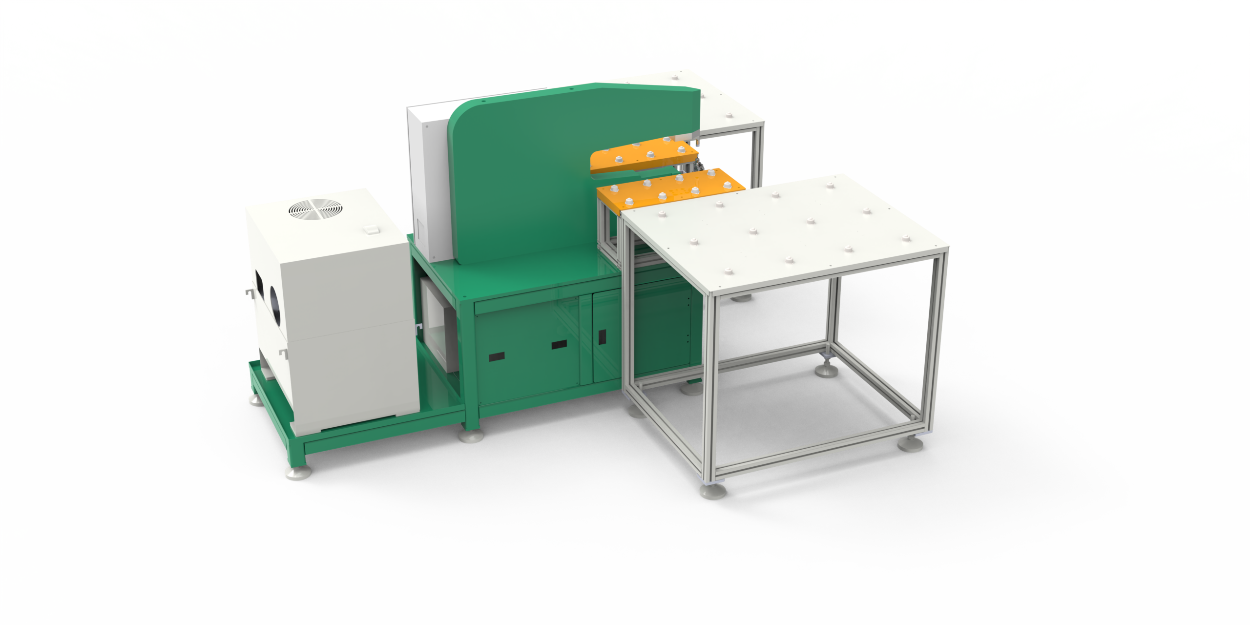
Start here for a self piercing riveting machine built around a sheet stack, rivet, die, access envelope and sample-joint approval. Options include standalone pneumatic or hydraulic equipment, CNC-servo equipment, and robot-compatible mounting.
- Pneumatic / hydraulic: 50 or 75 kN maximum punching force; stated 3 s cycle
- CNC servo: 5 or 8 t drive force; 100 or 200 mm stroke; stated 3 s cycle
- Available functions: Touchscreen, online monitoring, process/result storage, robot integration
Programmable servo route
Servo Riveting Assembly Systems
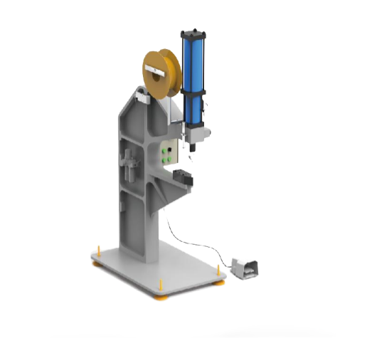
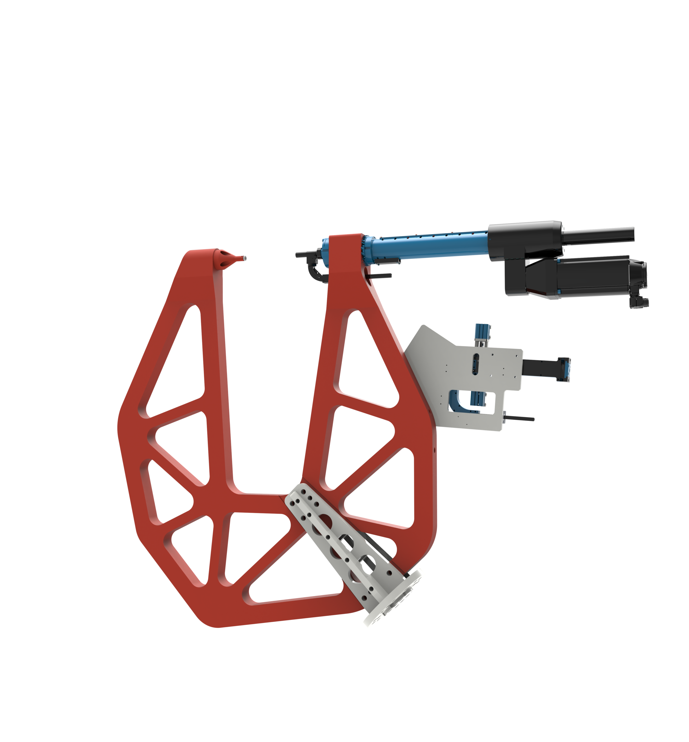
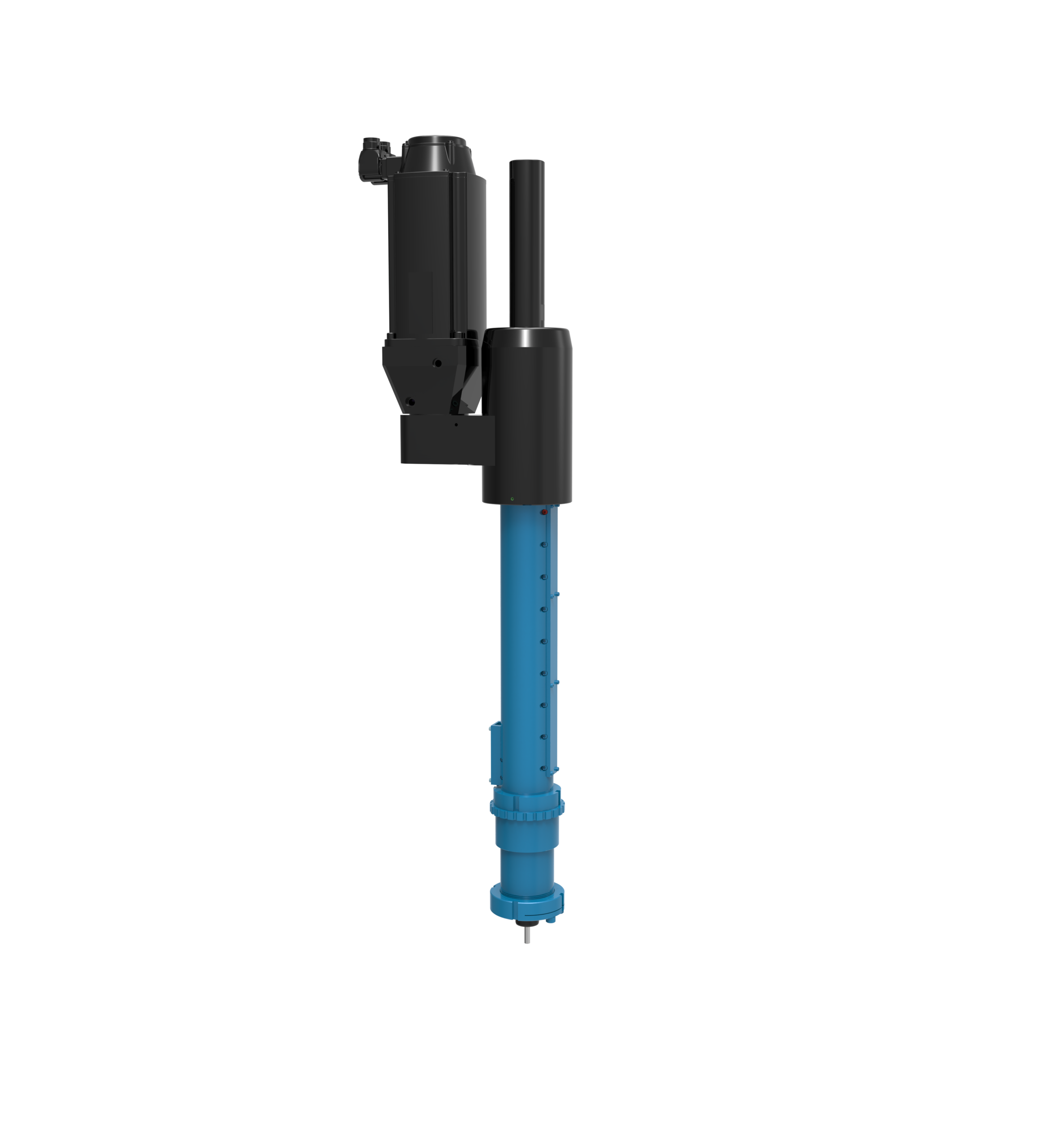
Use this route when the assembly needs programmable motion, force and position evidence, automatic feed, or a robot/fixed-frame installation. Supplied servo-system data supports an 80 kN power unit with a 200 mm effective stroke.
- Motion: 0–333 mm/s; ±2% pressure accuracy; 0.01 mm repeat positioning accuracy
- Life data: Machine ≥6 million cycles; motor ≥10 million cycles
- Service intervals: Minor at 1 million cycles; major at 3 million cycles
- Feed: 2 × 35 = 70 rivets; 0°/90° standard mounting directions
Application-line route
Riveting Equipment for Elevator & Rail Transit
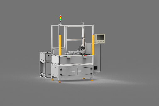
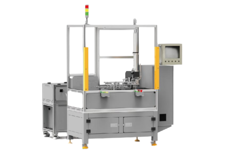
Choose a project-engineered line when fixture, material flow, inspection, robot motion and station controls matter more than a standalone press rating. Supported applications include elevator-car-bottom assembly, busbar self-piercing assembly and robot-integrated riveting cells.
- Modular and scalable station scope
- Quick-connect project layout
- Monitoring and production/process/result storage
- Remote access or control where specified
- Force-based monitoring and non-destructive inspection options
| Start with | Project emphasis | Next evidence needed |
|---|---|---|
| SPR machine | Self-piercing joint and gun/frame architecture | Material stack, rivet, access and sample joints |
| Servo assembly system | Programmable motion, force/position, feed and data | Force, stroke, cycle, feed variant and control interface |
| Application line | Fixture, robot, inspection and station delivery | Layout, takt, part flow, safety and line interfaces |
Use the Riveting System Scope Blueprint to Define the Project
A common assumption is that a good joint plus a large enough machine force defines the project. It does not: a production riveting system also needs a reachable tool path, a controlled feed, inspection logic, line handshakes and a safe service method.
A layout can fail even when an 80 kN unit has enough rated force, because the gun misses the fixture window, feed orientation is wrong, or the robot recovery is undefined. Simitch engineers use the 4-layer blueprint to connect those risks with drawings, sample tests, interface records and acceptance evidence.
Leaving one of the 4 layers open creates a real project risk: a proven joint may not fit the fixture, a reachable gun may receive the wrong rivet, or a stable press cycle may fail the line handshake. For a US buyer or global production team, Simitch engineers the detailed review around drawings, sample parts, interface lists and acceptance criteria—not a one-line “robot ready” promise.
Request a Custom Four-Layer Review
Request a Detailed Engineering Review
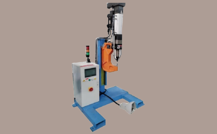
Layer 1: Joint Definition
- Buyer supplies: material, thickness, rivet, locations and acceptance needs
- Simitch configures: forming approach, tool and die concept
- Evidence: sample section, head condition and joint checks
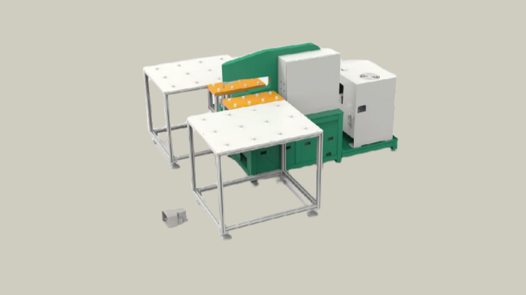
Layer 2: Equipment Architecture
- Buyer supplies: access envelope and target takt
- Simitch configures: gun/frame, throat, opening, feed and mounting
- Evidence: approved layout and configuration sheet
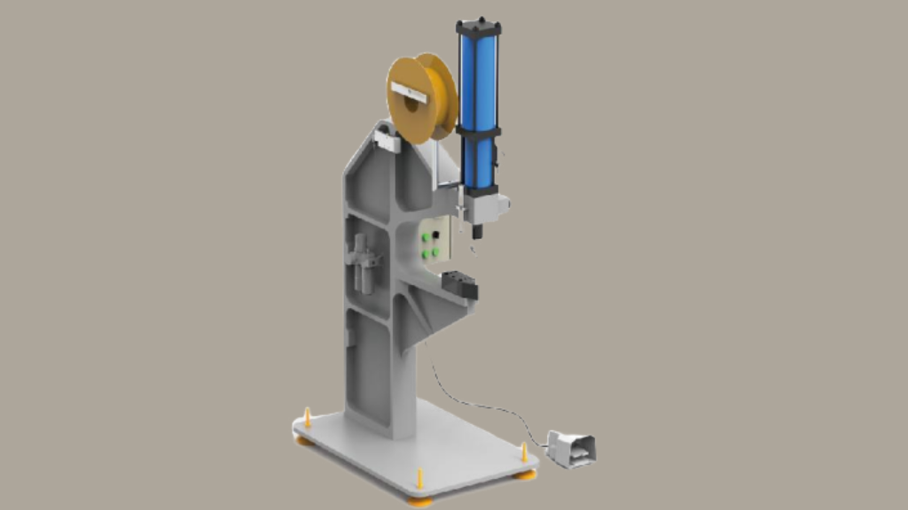
Layer 3: Process Evidence
- Buyer supplies: quality risks and retention needs
- Simitch configures: presence, seating, force/position and result logic
- Evidence: trace, alarm, recipe and repeat-run tests
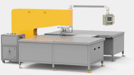
Layer 4: Line Integration
- Buyer supplies: robot, fixture, PLC and site rules
- Simitch configures: interfaces, safeguarding scope and recovery flow
- Evidence: handshake, risk review, commissioning and handover
“A project is ready to quote when the joint, access, process evidence and line boundary can be reviewed together. If one layer is missing, the number on the quote is not yet comparable.”— Simitch Engineering Team
Match Configuration Data to the Exact Machine Architecture
A mismatched material stack can crack, under-flare or lose the required interlock. The same discipline applies to machine data: force, stroke, speed, throat, opening, feed capacity and cycle time mean little until each figure is bound to the selected architecture.
| Decision field | Self-piercing machine or gun | Servo assembly system | Application line |
|---|---|---|---|
| Force and motion | Confirm the selected pneumatic, hydraulic or CNC-servo unit | Confirm force, stroke, speed and control window | Derive from station and joint design |
| Access | Confirm frame/gun envelope and mounting | Choose C frame, robot gun or floor-standing gun | Check fixture, robot path and line layout |
| Feed | Confirm rivet and feed option | Confirm lane, size and orientation; one magazine cannot mix 3 mm and 5 mm | Confirm part and rivet flow by station |
| Quality evidence | Online monitoring and stored results where selected | Force/position plus presence, seating and anti-tilt checks where selected | Station and line acceptance plan |
| Final authority | Approved configuration sheet | Approved system specification | Approved technical agreement and layout |
IMPORTANT
Do not compare unbound numbers
Those 80 kN, 200 mm, 0–333 mm/s, ±2% and 0.01 mm values belong to the named servo power-unit data. We will not claim that those figures apply to every riveting product, nor will we treat a stated 3 s machine cycle as a guaranteed finished-station takt.
- Configuration sheet
- Approved layout
- Sample joint
- Acceptance plan
Connect Feeding, Quality Data and Robotics in One Automated Riveting Cell
An automated riveting system is a chain, not a single actuator. A feeder fault can create an empty joint, stacked rivets or a reversed rivet; a controls fault can pass the wrong recipe; a recovery gap can turn one alarm into extended production delay.
1. Part & Joint
2. Tooling & Feed
3. Press / Servo Motion
4. Quality Decision
5. Result Storage
6. Line Response
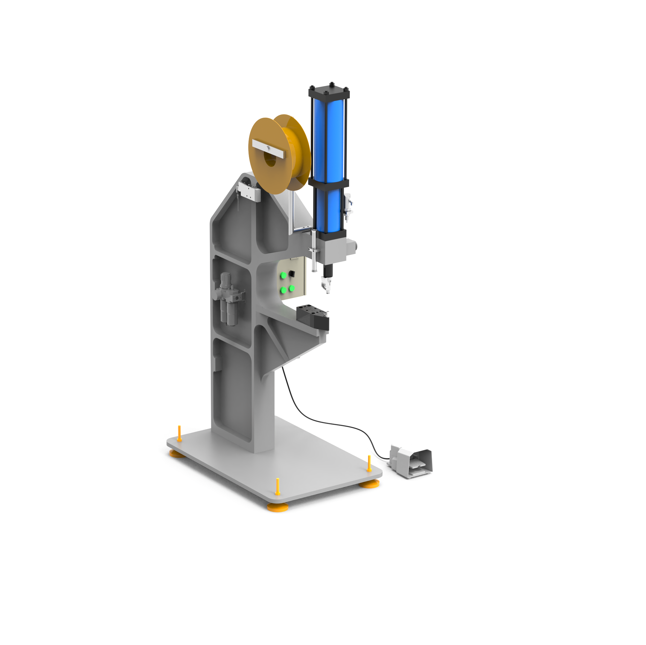
Sheet-Metal Subassembly
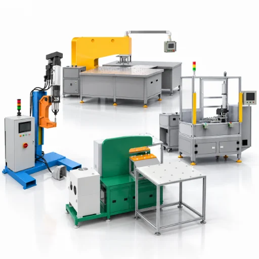
Elevator Car-Bottom and Busbar Assembly
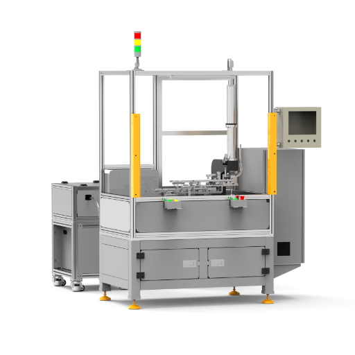
Rail-Transit and Robot Cells
An 80 kN/200 mm servo unit does not always make a robot assembly ready, because fixture access, feed recovery, PLC response and joint inspection can still fail. Simitch engineers the detailed cell test around the actual production part, robot path and operator recovery rather than treating a machine cycle as line proof.
Request a Custom Automated Cell ReviewA detailed cell checklist should trace the part from identity check to result storage, then test what happens when feed, motion, quality or communication fails. Simitch can build the custom engineering checklist around the selected 80 kN/200 mm servo unit, a different machine architecture or a project line, but the final test must reflect the real fixture, PLC, robot and operator response.
Request a Custom Cell Engineering ReviewMore sensors and stored signals create better process visibility, but they do not always prove the metal joint itself. A force-displacement pass can still miss rivet offset, cracking or button loss, so the acceptance plan needs both machine evidence and joint-level checks.
Review Your Robot and Line InterfacesDefine Acceptance Evidence Before Purchase
A pass/fail trace is not always a finished-joint verdict. TWI explains that each force-displacement curve can be compared with a characteristic benchmark and tolerance band, yet the relationship to final joint properties may be imprecise; peer-reviewed research also reports blind spots for offset, cracking and button loss.
PHASE 01
Before Build
- Approved stack and rivet
- Sample-joint criteria
- Layout and responsibility matrix
PHASE 02
Factory Acceptance
- Cycle and repeat-run test
- Presence, seating and anti-tilt checks
- Trace, alarm and storage checks
PHASE 03
Site Acceptance
- Robot/PLC handshake
- Safeguard and recovery test
- Fixture and peripheral verification
PHASE 04
Handover
- Operator and maintenance training
- Recipe and changeover control
- Service and controlled-energy scope
Joint evidence to discuss
- Rivet head condition, position and flushness
- Button condition, cracking, puncture and material damage
The joint can feature an interlock or undercut as well as a remaining bottom thickness where sectional checks are required by the design.
- Force/position curve, selected process limits and alarm response
- Inspection method, sample frequency and retention rules
Work with a Riveting Machine Manufacturer Built for Custom Equipment
Suzhou Simitch Machinery Co., Ltd. was established in 2006 as a mechanical equipment manufacturer focused on sheet-metal connection machinery. The company states that it moved from introduced clinching technology to independent research and development, then built its own clinching and precision pressing capability.
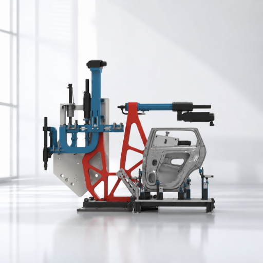
Mechanical equipment work centered on sheet-metal connection machinery.
Foreign clinching technology supported equipment-production and application experience.
The company reports a shift toward independent research, development and product work.
Simitch reports mastery of clinching and precision pressing technologies.
Simitch reports trademarks, multiple patents and independent production of key equipment and core parts.
Verify supplier evidence at the project level
To be upfront—and less grand than a “global leader” claim—the brand history above is supplied by Simitch. Patent identifiers, certification scope and named customer results were not independently matched for this page, so request the records that matter to your supplier audit and bind accepted evidence to the purchase file.
- Application review
- Sample-joint planning
- Configuration boundary
- Factory acceptance scope
- Handover scope
Plan Price, Lead Time and Support from the RFQ Inputs
Until tooling, feeding, fixtures, controls, safety, data and acceptance scope align, comparing machine prices offers no useful baseline. No reliable public data supports one fixed riveting machine price, savings percentage or payback period across all three system routes, so Simitch quotes from the project scope first.
- Rivet, die and material stack
- Force, stroke, speed and position
- Cycle or takt target
- Frame/gun access and mounting
- Rivet size, lane and orientation
- Changeover method and recipe count
- Fixture, robot and line controls
- Inspection, monitoring and data
- Guarding, installation and acceptance
Scope before savings
Bronze evidence: compare cost drivers, not invented returnsYour comparison should be based on an identical part volume, labor baseline, changeover plan, definition of rework, time allotted for maintenance, utilities, as well as scope of acceptance and installation limit. Without user input on these factors and an agreed upon calculation method, return on investment claims cannot be made.
- Part drawing or 3D model
- Material and thickness stack
- Rivet specification and joint locations
- Access envelope and fixture concept
- Target cycle or line takt
- Quality checks, alarms and data-retention needs
- Robot, PLC and upstream/downstream interfaces
- Destination, installation, training and acceptance scope
A repeat machine architecture with approved inputs can be planned differently from a new robot cell with custom fixtures and inspection. Finalize joint trials, controls interfaces, safety responsibilities and acceptance evidence before the schedule becomes a contract promise.
Send Your Part and Joint RequirementsRiveting Equipment Engineering Tools
Riveting System Architecture Selector
Identify the optimal riveting architecture for your specific application requirements. Evaluate technical feasibility and production efficiency.
Access SelectorRiveting System Comparison Explorer
Compare riveting systems based on force, cycle time, and material specifications. Make data-driven equipment decisions.
Access ExplorerRiveting RFQ Readiness Calculator
Assess your project specifications before requesting a quote. Ensure all critical engineering parameters are defined.
Access CalculatorFrequently Asked Questions
How do I choose the right industrial riveting machine?
Start with the stack, rivet, access and takt. Route the project to an SPR unit, servo system or application line only after those inputs are clear.
Which Simitch riveting equipment architecture fits my project?
An SPR machine fits a defined self-piercing joint and gun/frame task. A servo system fits programmable force, stroke, speed, position and feed needs, while an elevator, busbar or rail-transit line fits projects where stations, fixtures, inspection and line controls define the delivery. Ask Simitch to map your inputs against all three routes before freezing the layout.
Can Simitch integrate riveting equipment with a robot or production line?
Yes. Robot-compatible guns, mounting and project-engineered cells are within the supplied scope, but the RFQ must also name PLC handshakes, fixtures and safeguards.
What information is needed for a riveting equipment quotation?
Send the part drawing or 3D model, material/thickness stack, rivet specification, joint map, access envelope, target cycle, inspection method, data needs and line interfaces. Add the destination, utilities, installation work, operator training, maintenance handover and acceptance boundary. When each supplier receives this same package, procurement can compare what is included instead of comparing headline machine prices.
How much does an automated riveting machine cost?
No fixed figure applies across a standalone press, servo system and robot line. Scope drives the quote.
Can one system handle different rivet sizes?
It depends on feed and changeover design. The supplied dual-lane servo feed holds 2 × 35 rivets, yet one magazine setup cannot feed 3 mm and 5 mm rivets simultaneously. Simitch must confirm the rivet family, orientation, lane assignment, recipe control, changeover proof and wrong-rivet prevention before the machine specification is approved.
What quality data can a riveting system record?
Available scope can include production, process and result data, force/position traces, rivet-present status, seating checks and alarm states. Define the final tag list, pass/fail logic, sample rate, retention time, export format, user access, recipe history and recovery response in the system specification. For an SPR joint, pair those records with the agreed head, button, crack, interlock or section checks because a clean trace does not necessarily prove the formed joint.
How are machine specifications confirmed before an order?
Approve a configuration sheet, layout, sample-joint record and acceptance plan. Together they bind force, stroke, speed, throat, feed and cycle statements to the selected equipment.