Get in touch with Suzhou Simitch Machinery Co., Ltd Company

ISO Certified
Gas-Liquid Booster Cylinders, BS & BT Series
Gas-Liquid Booster Cylinders — BS & BT Hydro Pneumatic Cylinder Series
Simitch BS and BT hydropneumatic cylinders combine pneumatic approach movement with a short hydraulic power stroke for pressing, joining and forming equipment. Supplied BS catalogue data covers 11–970 kN output force at a 6 bar air-input condition, while both product families run from size 01 through size 100.
Request a Matched Quotation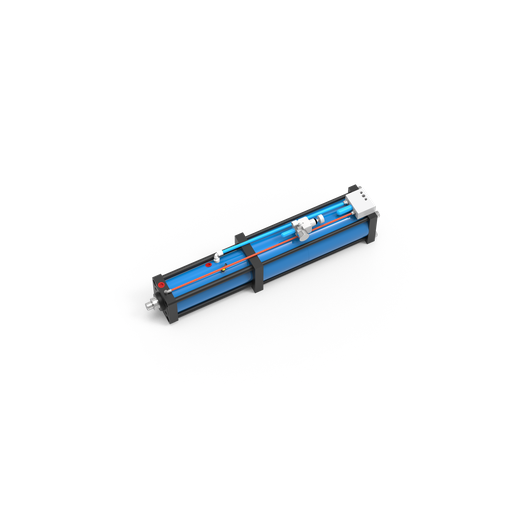
01
11–970 kN
BS catalogue output at 6 bar
02
BS01–BS100
BS model families
03
BT01–BT100
BT model families
04
51–69
Listed BS boost-ratio range
High-Force Work Stroke Without Beginning With a Full Hydraulic Power Unit
Full-force travel through a long approach wastes space and makes the drive harder to match. Hydro-pneumatic actuation separates fast travel from the high-force work zone, so the piston rod approaches pneumatically and the intensifier raises oil pressure only after contact with the workpiece.
Stage 01
Fast Approach Stroke
Compressed air moves the rod through the non-working distance at speed. Tooling should reach the work area without using the high pressure chamber for the whole stroke.
Stage 02
Intensified Power Stroke
At the work zone, the pneumatically controlled valve sequence activates the intensifier. The oil side can intensify pressure to produce the short, higher-force push required by the press process.
Stage 03
Return And Reset
After the operation, the cylinder retracts and prepares for the next cycle. Controls must confirm the safe return position before the machine allows another part load.
When This Drive Pattern Fits
- A relatively long, low-force approach followed by a short high-force stroke.
- Press-fit assembly, riveting, clinching, forming, punching or clamping with a known work zone.
- A machine layout that can integrate the required air preparation, valve control, oil circuit and sensors.
- A process where the total stroke and intensified work distance can be defined before model approval.
When To Review Another Drive
- High force is needed through most of the overall stroke.
- Closed-loop position control or an adjustable force-distance profile is the primary process requirement.
- The plant cannot supply stable compressed air, or the duty cycle makes air consumption a deciding constraint.
- Maintenance personnel cannot support the pneumatic and hydraulic service points of a hybrid system.
Why Simitch Screens The Cycle Before The Model
The risk of a force mismatch grows because a 6 bar catalogue condition does not describe every production load path. Unlike a conventional force-only screen, Simitch engineers review the application sequence, and the trade-off between fast travel and high-force distance stays visible.
Honest selection starts with one rule: this arrangement is a candidate, not an automatic replacement for every hydraulic cylinder or pneumatic press. Send the force-distance requirement and cycle sequence to request an engineering review.
System-Standard Context
ISO 4414 frames pneumatic-fluid-power review at the machinery-system level. It supports checking design, installation and maintenance boundaries; it does not validate a Simitch performance claim.
Choose Between the BS and BT Hydro Pneumatic Cylinder Series
Force capacity alone can hide how force is delivered through the stroke. Start with force, then check the installation envelope, approach travel, high-force work length, mounting pattern and control requirement before deciding which drawing deserves a detailed review.
BS Series
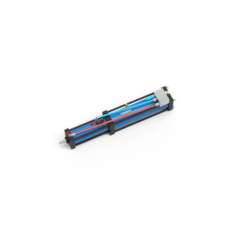
- Model families: BS01, BS02, BS04, BS08, BS15, BS20, BS30, BS50, BS75 and BS100.
- Supplied 6 bar output-force data: 11–970 kN across the listed families.
- Catalogue variants include spring and air-spring notes, multiple travel codes and port sizes from G1/8 to G1.
- Final choice depends on the specific model row and its lettered drawing dimensions.
BT Series
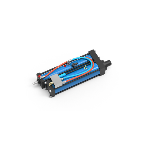
- Model families: BT01, BT02, BT04, BT08, BT15, BT20, BT30, BT50, BT75 and BT100.
- The supplied BT tables contain dimensional rows, mounting threads, port sizes and variant notes.
- BT rows add the catalogue fields P and X, which must be read against the matching product drawing.
- No construction difference is inferred from the series name alone.
Three Inputs Before Selecting a Series
1. Working force
State the required force at the tool and explain what the process is doing. Press-fit joints, punches and clamps may need different force delivery even when the peak number looks similar.
2. Installation envelope
Provide the available length, width, mounting face and direction. Drawing review prevents the rod, body, ports or nearby tooling from creating a mismatch.
3. Stroke definition
Separate total travel from the short hydraulic work stroke. Also state where contact occurs and whether the contact point can shift between parts.
Series boundary remains drawing-led
Supplied files do not contain a prose definition that proves a structural BS-versus-BT distinction. Simitch will not claim one from model names; send your mounting drawing and process inputs for confirmation.
Example screening context
In a production assembly fixture, a 100 mm travel code and a 6 bar air condition still do not prove that the body, ports and intensified stroke fit. Mismatch risk remains because the application envelope comes from the machine; Simitch engineers use the detailed drawing and RFQ inputs to confirm it.
Shortlist the force family first, but release a model only after the work point, travel, mounting envelope and control sequence have been checked together.
Application review principle — Simitch Engineering Team
Match Output Force, Stroke and Dimensions to Your Press
Surface finish, temperature and lubrication can change press-fit force, so sample parts may be needed. Treat the table as a screening tool; the final model depends on actual process force, tooling stiffness, alignment, travel, sensors and the machine control plan.
How to Read the Selection Data
Check 01
Screen by Output Force
Start with the required working force and the catalogue input condition. Do not convert a nominal force into process acceptance without a sample or engineering review.
Check 02
Verify Force Delivery
Confirm where the power stroke begins and how far it must continue. Ram alignment, tooling deflection and the real force path can change the result.
Check 03
Approve the Complete Fit
Check overall stroke, body dimensions, ports, mounting threads, rod end, sensors and service access. Add the machine-level guarding and isolation review before release.
Integration and Pressure-Safety Review
- Ram alignment to the physical center can still create side loading if the maximum force path is elsewhere.
- An oversized or undersized load cell can reduce useful accuracy and resolution; monitoring hardware must match the process range.
- Trapped air makes oil-side motion spongy and can disturb smooth stopping, while undersized oil lines can slow travel and reduce usable force through pressure drop.
- The listed 280–380 bar maximum oil-pressure range makes depressurization, guarded fluid components and safe isolation part of maintenance planning.
The Cylinder Is Not the Machine Safety System
OSHA 1910.212 requires machine guarding and point-of-operation protection where an injury hazard exists. High-pressure fluid guidance also calls for pressure release, overpressure protection, shutoff and repair controls; final requirements depend on the complete machine and local rules.
Evidence-Led Release Rule
Pressure and fit problems occur because force data alone cannot prove a production result. Unlike a force-only selector, Simitch engineers connect the 6 bar catalogue basis, ISO and OSHA system boundaries, precise tooling needs and the machine drawing before a model is released.
Application Fit for Pressing, Assembly and Forming Equipment
Hydro pneumatic press cylinders fit when the process has a clear contact zone and a short high-force action. Choosing from the application name alone creates risk, because tooling, part variation, access, cycle rate and acceptance criteria still decide the correct actuator.
Clinching
Confirm sheet stack, joint geometry, tooling force and accessible mounting direction. Simitch’s early equipment experience includes sheet-metal connection machinery, but the cylinder still needs a process-specific review.
Press-fit assembly
State interference, material, lubrication and the target force-distance window. Sample parts help when surface finish or temperature can shift insertion force.
Riveting
Provide rivet type, forming force, set height and required approach distance. Tool alignment matters because an off-axis load can wear the rod and seals.
Forming
Share material, thickness, tool geometry and required displacement under load. Short power strokes may fit, while deeper forming can require another drive architecture.
Punching
Give material shear area, tool clearance, breakthrough behaviour and return requirement. Peak force is not the only issue; shock, tooling and frame stiffness need attention.
Clamping
Define clamp force, dwell time, safe release and whether pressure must remain during another operation. Separate holding measures may be needed if stored energy creates a risk.
Process monitoring is not the same as servo control
Force-distance monitoring can record a signature without turning the drive into a closed-loop servo press. If the process must change force or velocity continuously through the stroke, discuss the control objective before selecting a cylinder.
Search terms do not define the machine
A hydro pneumatic press, hydro pneumatic system or air over hydraulic cylinder diagram may describe several architectures. Simitch engineers still need the production application, 6 bar supply condition, force path and detailed drawing to prevent a mismatch.
Hydro Pneumatic vs Pneumatic and Full Hydraulic Approaches
Pneumatic and hydraulic drives solve different force-distance problems, and a hybrid drive combines parts of both. Selection depends on the required stroke profile, plant utilities, controls, footprint, cycle pattern and maintenance capability.
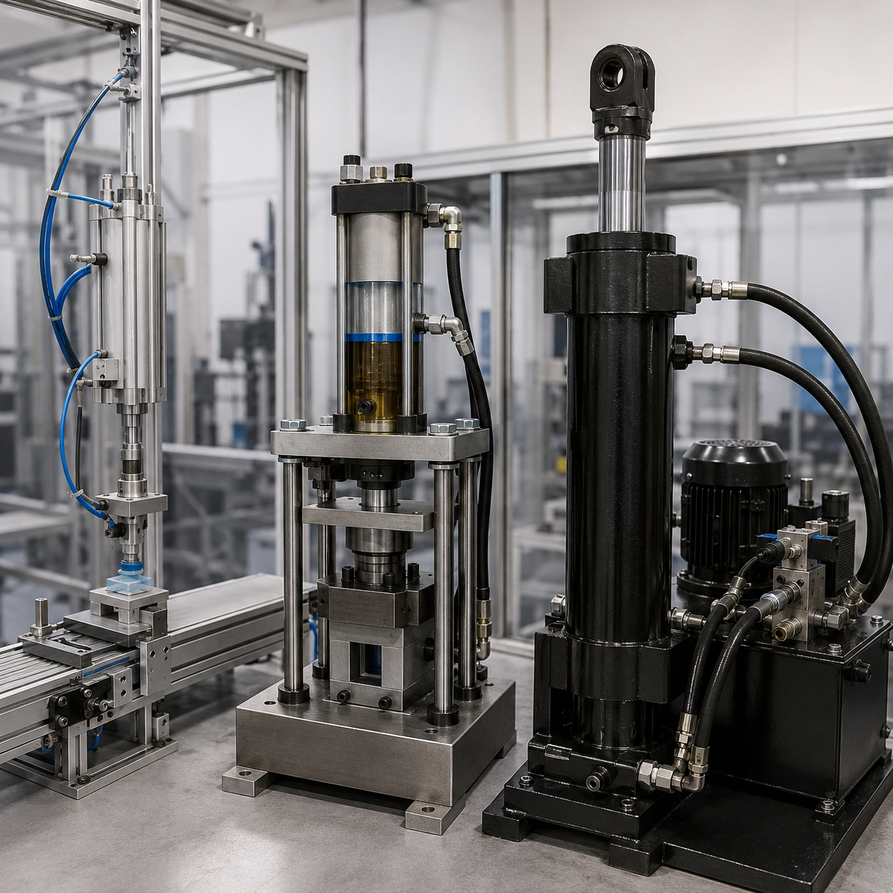
| Decision Point | Pneumatic Cylinder | Hydro Pneumatic Cylinder | Full Hydraulic Approach |
|---|---|---|---|
| Force Pattern | Air pressure acts through the pneumatic bore during the stroke. | Low force approach plus a short intensified hydraulic work stroke. | Hydraulic pressure can drive the required force profile through a longer stroke. |
| System Elements | Air preparation, valves, cylinder and controls. | Compressed-air circuit, pneumatic valve control, oil reservoir or chamber, intensifier and actuator. | Pump, power unit, tank, valves, filtration, hydraulic cylinder and controls. |
| Selection Data | Bore, air pressure, thrust, speed and stroke lengths. | Approach stroke, power stroke, output force, boost ratio, dimensions and oil-pressure boundary. | Pressure, flow, cylinder area, stroke, heat, duty cycle and power-unit capacity. |
| Control Question | Is air compressibility acceptable for the process? | Is staged movement acceptable, and are monitoring or active motion control needs clear? | Does the process require hydraulic control through more of the travel? |
| Maintenance Points | Leaks, air quality, seals, alignment and valve condition. | Air-side items plus hydraulic oil, seal integrity, trapped air and high-pressure isolation. | For full hydraulic systems: oil cleanliness, leaks, filters, pump, valves, heat and pressure controls. |
| Best-Fit Screen | Lower-force motion where a conventional pneumatic system meets process variation. | Fast approach and a short high-force press action in a suitable machine envelope. | Longer or more adjustable hydraulic work where the extra power-unit scope is justified. |
Plant-Air Cost Is Part of the Decision
No Universal Savings Claim
Bronze TCO Decision Card
DOE Better Plants notes that more than 80% of compressor input energy can be lost as heat. Actual ownership cost depends on air pressure, leaks, controls, inappropriate use, duty cycle, maintenance and the specific cylinder’s consumption.
Data Needed for Comparison
Required force-distance curve and cycles per hour.
Available shop-air pressure at the machine during peak demand.
Air consumption for the selected specification.
Existing hydraulic infrastructure and service skills.
Monitoring, sensing and motion-control requirement.
Beware of a Single-Feature Comparison
Removing a separate hydraulic power unit may reduce some components in suitable applications, but compressed air is not free and a hybrid drive still contains hydraulic fluid. We will not claim lower total cost until the site data and model duty are known.
Comparison Rule
Utility-cost risk remains because the DOE figure describes compressed-air systems, not one Simitch cylinder. An engineering review should connect that system-level context with production duty, precision-control needs and the actual model; the trade-off stays conditional.
Hydraulic and pneumatic systems place different demands on utilities, service skills and controls.
For applications requiring staged movement, a pneumohydraulic configuration may support productivity without claiming the same result across different applications.
Engineering and Manufacturing Support From Simitch
Unknown supplier claims create procurement risk when they are not tied to evidence. Simitch therefore keeps this section to the company history supplied for the project and does not turn missing certificate, capacity, lead-time or customer-result data into promises.
2006
Established as Suzhou Simitch Machinery Co., Ltd., with a focus on mechanical equipment and sheet-metal connection machinery.
Early stage
Introduced foreign clinching technology and built practical experience in equipment production and application.
Development
Moved from technology introduction toward independent research and development in clinching and precision pressing.
Current basis
Reports independent trademarks, multiple technical patents, and independent production of key equipment and core parts.
Established 2006
User-provided company history
Pressing Experience
Clinching and precision pressing focus
Independent R&D
Technology development stated by the company
Core-Part Production
First-party capability statement
What the Engineering Review Should Return
Model shortlist
Candidate BS or BT model families tied to the required force, total travel and power stroke, with open questions called out.
Drawing check
Compare the installation envelope, mounting face, rod connection, ports and service access against the model row.
Control boundary
Required sensors, valve sequence, monitoring needs and machine-level safety items remain visible for the system designer.
Gas-Liquid Booster Cylinders, BS & BT Series Engineering Tools
BS Force-to-Model Selector
Enter the working-force requirement to find the first BS family whose supplied catalogue force meets it at 6 bar. This is a shortlist, not a final engineering release.
Access Selector ➔BS/BT Dimension Comparison Explorer
Select two supplied catalogue rows to compare their lettered dimensions, mounting thread, port and variant note. Letter codes must be read against the matching Simitch drawing.
Access Explorer ➔BS/BT RFQ Readiness Builder
Complete the six selection inputs used for an initial Simitch model match. The readiness score shows which items are still missing and prepares a copyable project summary.
Access Builder ➔FAQ: Hydro Pneumatic Cylinder Selection
Compressed air drives the approach movement, then an oil-side intensifier activates near the work zone. Intensified hydraulic fluid produces the short power stroke before the actuator returns for the next cycle and resets the machine sequence.
In pneumatics, cylinder thrust comes from air pressure acting on piston area. Hydro-pneumatic cylinders add an intensified hydraulic work stage for fast approach plus a shorter, higher-force action, while also adding oil-side seals, lines or chambers and maintenance points.
Begin with measured or calculated force at the workpiece, then account for tooling, alignment, material variation and the full force-distance requirement. Peak force alone misses how load develops through the stroke, how the frame deflects and whether the tooling reaches the part squarely. Sample trials are worth arranging when friction, temperature, lubrication or part tolerance can shift the result; Simitch can then compare the requirement with the catalogue condition and identify the questions that remain before model approval.
Total travel must bring the tool from its safe start point to the completed position. Power-stroke length should cover the true high-force distance, including known contact-point variation, without extending the intensified stage through unused travel.
Use required force, installation envelope, mounting direction, total travel and power stroke as the first screen. Next, compare the specific row’s body dimensions, mounting threads, port size, rod connection and variant note with your machine. Supplied files do not define a categorical BS-versus-BT construction difference, so the series name cannot finish the selection; send both the process data and installation drawing to Simitch for confirmation, especially when nearby tooling or service access is tight.
Provide output force, air pressure at the machine, approach and power-stroke lengths, mounting envelope, controls, sensors, rod end, quantity and destination. Part or machine drawings make the quotation easier to compare and reduce follow-up questions.
Price is affected by model family, force size, stroke code, body and mounting dimensions, ports, sensor needs, rod-end details, quantity and custom engineering. Commercial scope may also include drawing work, sample review, inspection records, packing and freight to the destination. Compare quotes only after each supplier has received the same process and interface inputs; otherwise, a low figure may simply omit the option, travel or support item that another quote includes.
Custom requirements can be reviewed, but feasibility is not assumed from a short description. Submit the drawing, interface dimensions, sensing purpose and load path so Simitch can check the selected family.
No. Plant-air generation has losses, and actual cost depends on compressor efficiency, system pressure, leaks, controls, duty cycle and cylinder consumption. DOE Better Plants reports that more than 80% of compressor input energy can be lost as heat, but that figure does not predict the cost of a particular cylinder. Compare measured air conditions and cycle demand with the hydraulic infrastructure already on site, then include maintenance access, oil-side service points and downtime before deciding which drive costs less.
Complete-machine design needs a risk assessment, point-of-operation guarding, safe controls and energy-isolation provisions suited to its jurisdiction. Maintenance planning must also address stored pressure, depressurization, high-pressure fluid injection risk and guarded components. The cylinder selection page cannot replace that system review.