Get in touch with Suzhou Simitch Machinery Co., Ltd Company

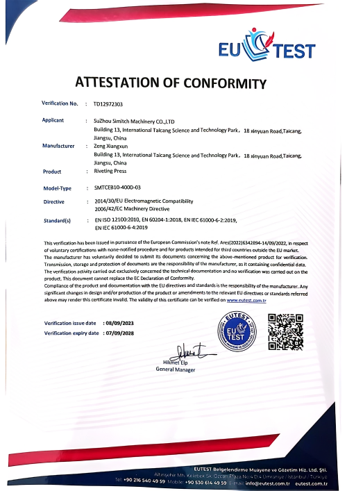
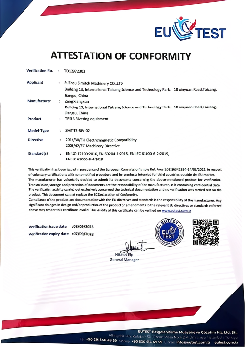
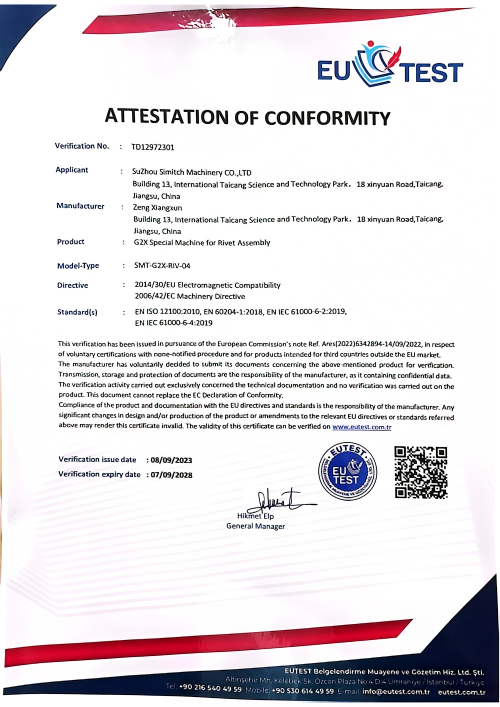
ISO Certification
Talk to an Engineer About Your Application
Pneumohydraulic Drive Cylinders
Pneumohydraulic Drive Cylinders for High-Force Pressing
Pneumohydraulic drive cylinders combine fast pneumatic travel with a hydraulic power stroke. This gives machine builders a practical route to high press force without making the entire movement a high-pressure stroke. From there, SIMITCH divides the category into integrated BS/BT cylinders and split AT/HZ working-cylinder systems, then checks the choice against required force, three stroke phases, plant air, duty, space, controls and machine safety.
2 routes
Integrated BS/BT or split AT/HZ3 strokes
Approach, power and return inputs8 inputs
Application brief for engineering reviewNo guessed data
Pressure conditions stay attached to ranges↺ Click to Switch View
11–970 kN
BS Force Range at 6 Bar
13–1,030 kN
AT Range at 400 Bar Oil Input
48–492 kN
HZ Range at 250 Bar Oil Input
Since 2006
Mechanical Equipment Manufacturing
Fast Pneumatic Travel with a High-Force Hydraulic Power Stroke
A press cycle wastes time when full pressing force is carried through the tool-positioning travel. A pneumohydraulic drive uses compressed air for the approach, switches to intensified oil pressure near the work, and returns after the power stroke.
Screen the cycle before releasing hardware
Failure begins with force mismatch because 6 bar data cannot describe tooling deflection, pressure recovery or plant-air drop. Our engineers relate the 6 bar BS, 400 bar AT and 250 bar HZ data to the tooling, assembly and production sequence, keeping the actual constraints in sight, unlike a generic force claim.
Approach stroke
Move to the workDuring approach, the pneumatic phase advances the piston quickly through non-working travel. Travel speed depends on available air flow and pressure, valve sizing and line losses.
Power stroke
Build force at contactFor the short high-force phase, the intensifier raises oil pressure. Always evaluate output force at the stated pressure condition and for the selected model family.
Return stroke
Reset the cycleReturn flow and pressure affect retract time, plant-air use and the pressure-recovery window for the next cycle. The return stroke therefore belongs in the sizing process rather than being treated as a byproduct.
Mechanism and safety boundary
ISO 4414:2010 defines general rules and safety requirements for pneumatic-system design, installation, maintenance and reliable operation. A public pressure-translator patent also illustrates why venting and trapped air matter in pressure translation.
The honest limit
Without the influences of tooling stiffness, pressure recovery, plant air and valve response, static force and stroke alone cannot predict a production cycle. Simitch engineers use the 6 bar, 400 bar and 250 bar results as evidence for family screening, then review the assembly, tooling and production sequence before releasing a model selection.
“If pressure, cycle and guidance are missing, a force row is only a screening value—not a configuration approval.”
Choose the Right SIMITCH Pneumohydraulic Cylinder Configuration
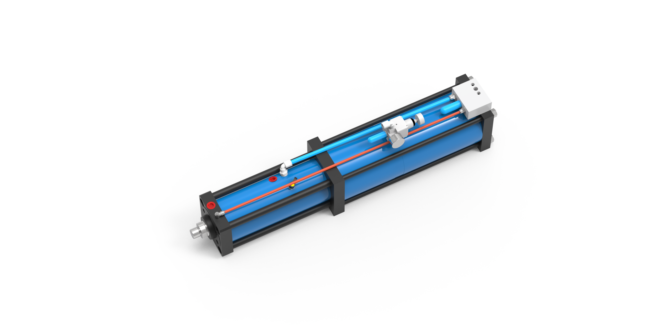
Begin with the architecture. An integrated gas-liquid booster cylinder keeps the pressure-conversion assembly with the working cylinder, while a split system separates the working cylinder from its intensifier and oil supply.
Avoid a layout mismatch
Installation delays and service risk rise when a system is selected by force alone because hose routing, oil volume and access were not checked. Our application engineers compare the 11–970 kN BS data with the 13–1,030 kN AT and 48–492 kN HZ data for tooling, assembly and production; the outcome is tied to the machine drawing, not just a family name.
Integrated routeBS & BT
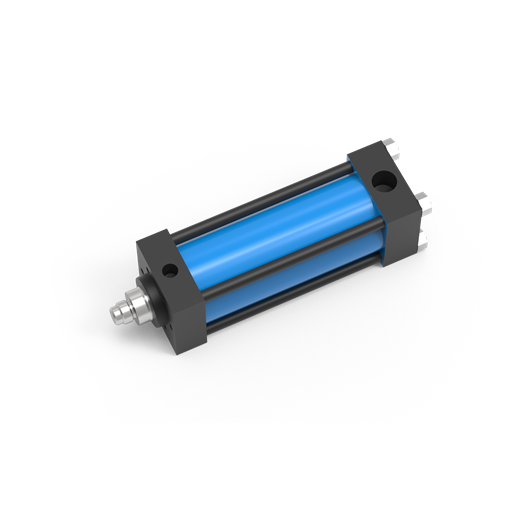
Gas-Liquid Booster Cylinders, BS & BT Series
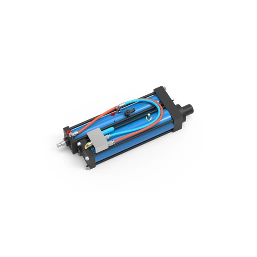
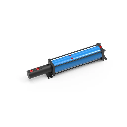
Use this route when the press can accept a combined pneumohydraulic cylinder package and the short power stroke occurs at the actuator. The supplied BS workbook supports 11–970 kN at 6 bar; its model table lists maximum oil-pressure values from 280 to 380 bar.
- Compact package for a direct machine mounting concept
- Fast approach plus high-force oil-pressure phase
Review BS and BT details, stroke choices and drawings on the child page
Review BS & BT Series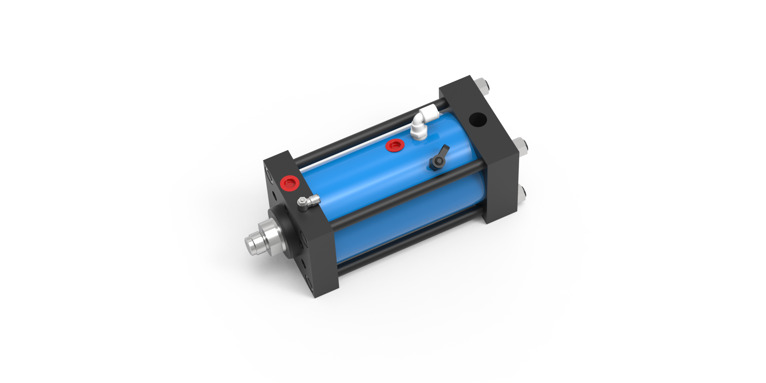
Split routeAT & HZ
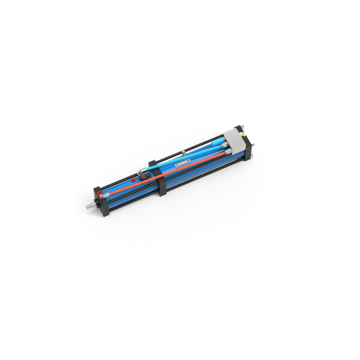
Split-Type Pneumohydraulic Working Cylinders, AT & HZ Series
Use this route when the working cylinder must fit close to the tooling while the pressure-conversion package sits elsewhere. AT covers 13–1,030 kN at 400 bar oil input; HZ covers 48–492 kN at 250 bar with bore sizes from 50 to 160 mm.
- Working cylinder separated from the intensifier package
- Useful where tooling access or installation shape controls the layout
- Review hose routing, oil volume, pressure recovery and service access
Selection note
Do not transfer one family’s pressure condition to another family’s force range. Final integration should also follow the pneumatic-system design and maintenance boundaries in ISO 4414:2010.
Integrated BS/BT or Split AT/HZ? Use the Simitch Boundary
Choosing by maximum force alone hides the real bottleneck. On paper, the package may fit yet fail the machine review because the tooling cannot guide side load, the hose path is poor, the plant air drops during demand, or maintenance access is blocked.
| Decision Input | Integrated BS/BT Direction | Split AT/HZ Direction | What Engineering Must Verify |
|---|---|---|---|
| Package location | Pressure conversion stays with the cylinder | Working cylinder and intensifier are separated | Available envelope and service clearance |
| Published force screen | BS: 11–970 kN at 6 bar | AT: 13–1,030 kN at 400 bar; HZ: 48–492 kN at 250 bar | Required force plus governing pressure |
| Tooling access | Best when the integrated body fits the press head | Working cylinder can sit close to tooling | Rod alignment, fixture stiffness and access |
| Hose routing | Reduced external separation between working and boost sections | High-pressure hose becomes part of the layout | Length, bend protection and safe routing |
| Oil volume | Matched inside the integrated assembly | Intensifier and working-cylinder volumes must be paired | Low- and high-pressure oil demand |
| Pressure recovery | Check recovery inside the planned cycle | Check recovery across intensifier, hose and cylinder | Cycle rate, dwell and repeat demand |
| Side load | External tooling guidance still required | External tooling guidance still required | Guides carry side load, not the piston rod |
| Maintenance | Access the integrated package as one unit | Access cylinder, intensifier and hose separately | Seal, bleeding and inspection plan |
| Controls and safety | Coordinate valves, sensing, guarding and isolation | Coordinate the same items across separated hardware | Machine risk assessment and energy isolation |
Assembly’s high-force pressing review recommends secondary tooling guidance to protect the cylinder rod from side loading. That advice aligns with the design, installation and maintenance scope in ISO 4414: the chosen architecture never removes the need for a machine-level review.
Hidden Bottleneck
A split-type hydropneumatic cylinder is not automatically the heavy-duty winner, and an integrated air over oil cylinder is not automatically the simpler winner. The least expensive family may not be the best fit once hose routing, recovery, side loading and service access are counted.
An Honest Comparison
A common assumption treats the split route as “larger” and the integrated route as “simpler.” The real trade-off covers package location, 11–1,030 kN family screens, pressure condition, tooling guidance, oil volume and maintenance access.
Where Pneumohydraulic Drives Fit Pressing and Joining Cells
Pneumohydraulic drives prove themselves when the short, high-force process follows a much longer, low-force part approach. Typical applications of this type include press fitting, clinching, crimping, swaging, staking, riveting, flaring and punching, but the process name is not a substitute for a load-and-tooling review.
Prevent process mismatch and rejected parts
Production risk rises because the same 6 bar supply can meet one tooling path and fail another after deflection, material variation or contact shift. SIMITCH connects the 5–52 mm power-stroke need, force path and acceptance criteria to clinching, assembly and press tooling; unlike an application list, this trade-off asks what the machine must prove.
Sheet-metal joining
Clinching and related joining cells need tool alignment, fixture stiffness and a controlled power stroke at the joint. Provide the material stack, joint geometry, required force, tooling layout and acceptance method.
- Confirm point-of-operation guarding
- Keep side loads in the guided tooling
- Define approach clearance and power travel
Press fitting and assembly
Interference fits, bush insertion and component seating depend on force and travel at the work, not only the cylinder ceiling. Include the fit condition, force window, dwell, end position and how the cell will detect a good part.
- State the force acceptance window
- Define sensing and control responsibility
- Review shock and off-axis loading
Forming and fastening
Crimping, staking, riveting and flaring may fit the fast-approach, high-force sequence. Tool geometry, material variation, production rate and recovery between strokes determine whether the selected drive remains inside its operating boundary.
- Share the worst-case material condition
- Include cycle and dwell profile
- Plan access for inspection and seals
Machine guarding is outside a cylinder table
OSHA 1910.212 requires protection from point-of-operation, nip-point and moving-part hazards and requires fixed machines to be anchored. Machine builders or integrators must connect those duties to the actual tooling, controls and access pattern.
Application proof before production
Point-of-operation guarding cannot be delegated to the cylinder, and tooling risk rises when material variation shifts the contact point. Because clinching, press fitting and riveting loads differ, SIMITCH asks for the 6 bar air condition, force path, 5–52 mm power-stroke requirement where applicable, sample or drawing evidence, and production acceptance criteria.
Where another drive may win
Unlike a short-power-stroke press, an application needing high force through most of its total travel may not suit this architecture. That trade-off protects the machine builder from forcing a pneumatic press cylinder into a process that needs another control or actuator concept.
Specify A Pneumohydraulic Drive For Your Machine
A vague request for “an air hydraulic cylinder” forces engineering to guess at the pressure condition, working travel and installation boundary. With the Eight-Input Application Brief, Simitch can screen the family and identify what still needs a drawing, test or risk review.
Normalize The RFQ Before Comparing Suppliers
Quote mismatch and procurement delay happen when one supplier includes a 400 bar intensifier, sensors and hose scope while another quotes only a working cylinder. Simitch uses the eight inputs for production, tooling and assembly review; unlike a comparison based only on price, the trade-off identifies the missing drawing, test or safety item.
Required Force
State working force, any force window and the process condition that creates the peak load.
Three Stroke Phases
Separate approach stroke, hydraulic power stroke and return stroke instead of sending one total travel value.
Plant Air
Supply available pressure at the machine, flow capacity, air-quality treatment and expected pressure variation.
Dynamic Duty
Include cycles per minute, dwell, shift pattern, recovery time and any shock or rapid reversal.
Installation Envelope
Provide available length, width, mounting orientation, hose path and maintenance access.
Tooling And Guidance
Show how the fixture guides side load and how the rod connects to the tool or slide.
Controls And Sensing
Define valve logic, position sensing, pressure monitoring, interlocks and good-part acceptance signals.
Safety And Acceptance
Identify who owns guarding, stored-energy isolation, risk assessment, commissioning checks and final documentation.
Pricing Factors, Not A Guessed Price
Series, force, stroke, mounting, sensors, intensifier pairing, hose scope, controls and documentation change the quoted package. Share the brief for a detailed quotation based on the actual application.
Service Boundary
OSHA 1910.147 requires hazardous stored or residual energy to be relieved, disconnected, restrained or otherwise rendered safe before service. Isolation points and verification belong in the machine plan.
Standards
ISO 4414
Pneumatic-system design & safety reference
OSHA 1910.147
Hazardous-energy control boundary
OSHA 1910.212
Point-of-operation guarding boundary
FIRST-PARTY DATA
Conditions traced to supplied workbooks
Simitch Manufacturing Context
Suzhou Simitch Machinery Co., Ltd. was established in 2006 as a mechanical equipment manufacturer focused on sheet-metal connection machinery. After introducing foreign clinching technology in its early stage, the company moved toward independent research and development in clinching and precision pressing. Buyers planning the joining cell can also review the related Simitch clinching machine configurations.
×
![]()
Pneumohydraulic Drive Cylinders Engineering Tools
Pneumohydraulic Family Force Screener
Enter the required working force and preferred package route. The result checks only the verified SIMITCH family ranges and keeps each pressure condition visible.
Access Tool →Integrated vs Split Configuration Guide
Use four installation questions to identify a starting direction. The guide does not assume that split always means heavy duty or that integrated always means simpler.
Access Guide →Eight-Input RFQ Readiness Checker
Mark the information already available for the application. A complete brief reduces supplier-scope mismatches and shows which drawing or test still needs attention.
Check Readiness →Common Pneumohydraulic Cylinder Selection Questions
Searches for “pneumohydraulic drive cylinder sizes,” “pneumohydraulic drive cylinder price,” or “pneumohydraulic cylinder manufacturers” reach the same decision boundary: the series name is not enough. An air over hydraulic cylinder, air over oil cylinder diagram, or air over oil intensifier label also needs the actual pressure path and internal architecture confirmed.
Terminology is not a drawing
Industry sources do not always use pneumohydraulic and hydropneumatic in the same way. Confirm whether air and oil are separated, which piston creates the power stroke, and what the quoted assembly includes. For the surrounding pneumatic system, ISO 4414 supplies a design and safety reference; it does not identify the product’s internal architecture.
How does a pneumohydraulic cylinder work?
Pneumatic movement handles approach and return, then an intensifier raises oil pressure for the short power stroke. Final force depends on the selected geometry and the pressure condition stated for that family.
Is a gas-liquid booster cylinder the same as an air over oil cylinder?
These terms often describe the same pressure-translation idea, but product architecture varies. Confirm whether the unit is integrated or split, which stroke receives hydraulic force, and which components are included in the quoted package.
When should I choose BS/BT instead of AT/HZ?
Start with the machine envelope. BS/BT is the integrated route; AT/HZ separates the working cylinder from the pressure-conversion package and adds hose, oil-volume, recovery and access decisions.
Can I compare the 970 kN, 1,030 kN and 492 kN limits directly?
Only when the governing conditions stay visible. BS is stated at 6 bar air, AT at 400 bar oil input, and HZ at 250 bar oil input, so the numbers screen families rather than create a pressure-free ranking.
Does removing a hydraulic power unit guarantee lower energy cost?
No. Compressor efficiency, distribution pressure, leaks, storage, valve control, cycle time and return pressure all affect the real result; calculate from the machine’s measured or specified duty rather than the architecture name.
What can cause slow retraction or oil in an air line?
A reviewed maintenance discussion reported oil migration and slow retraction in one air-over-oil system and considered seal leakage and bleeding. Treat those symptoms as a reason for isolation and diagnosis under the correct service procedure, not as proof of one universal failure mode.
Why does side loading matter?
Guided tooling should carry side load while the cylinder rod transmits axial force. Off-axis load can raise wear and damage risk, so include the tool-guidance concept with the request.
What information is needed for a pneumohydraulic drive cylinder price?
Provide required force, approach, power and return strokes, plant air, cycle and dwell, envelope, mounting and guidance, sensing and controls, plus safety and acceptance responsibilities. SIMITCH can then match the product route and define what the quotation includes.