Get in touch with Suzhou Simitch Machinery Co., Ltd Company

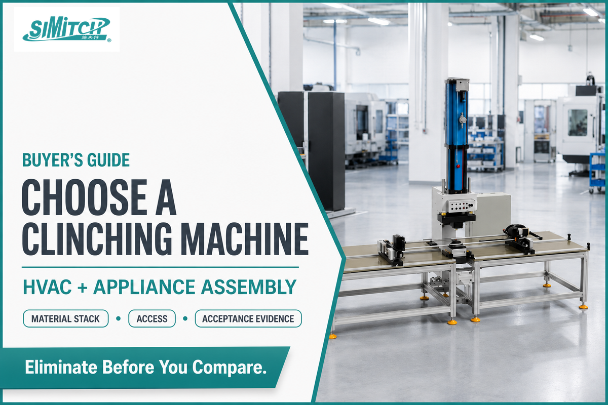
Clinching machines for HVAC & home appliance assembly are selected by eliminating configurations that fail the part’s material, access, production, or acceptance requirements. Start with the finished assembly rather than a press catalog. Record the sheet grade, coating, thickness of each layer, punch-side and die-side order, flange space, access from both sides, required joint loads, handling method, cycle demand, and acceptance evidence. Then use a sample trial to connect the punch, die, machine, recipe, and measured joint to one approved configuration. Even a high force rating can’t rescue a tool that can’t reach the joint, a flange that can’t support the die, or a stack that cracks before it forms an interlock. For HVAC ducts, dampers, appliance panels, and inner tubs, the right purchase is therefore the configuration that passes the actual part trial and production-scope review, not the machine with the largest number on its data sheet.
For product-family context, see SIMITCH clinching machines.
Short answer: Disqualify machines in this order: sheet stack, two-sided tool access, flange and edge space, part handling, joint load, tool pairing, production duty, utilities and controls, then acceptance evidence. Compare price only after the same accepted-joint definition is attached to every quote.
- ✔ A material total such as “2.0 mm” is incomplete without grade, coating, layer order, and individual thickness.
- ✔ Reach, throat, die landing, nearby bends, and guarding can eliminate a machine before force is calculated.
- ✔ A sample isn’t accepted until its material, tool, recipe, measurements, load test, failure mode, and release owner are linked.
- ✔ Published SIMITCH values below are configuration records, not promises for an untested part.
What Does a Clinching Machine Need to Prove Before Selection?
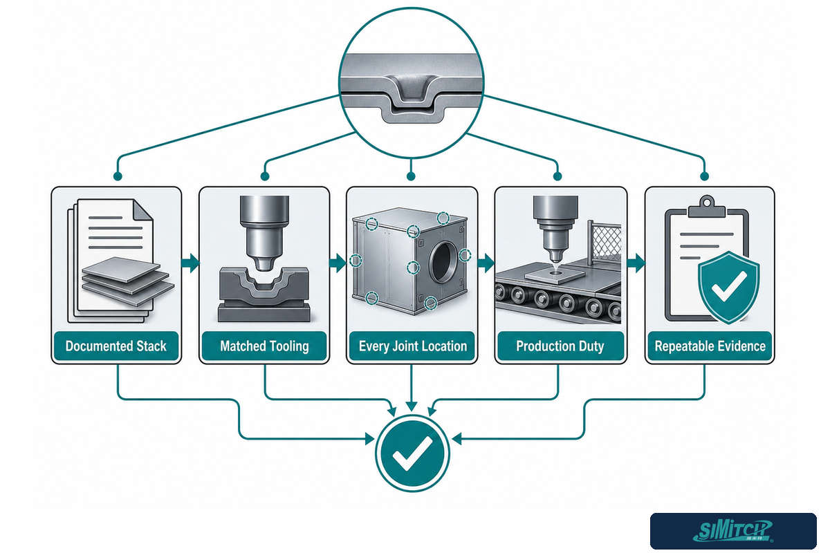
Selection must prove that one specific punch-and-die set can form an acceptable mechanical interlock in your documented sheet stack, at every required joint location, at the planned production duty. That statement has three parts: joint feasibility, physical access, and repeatable evidence. Dropping any one of them turns a machine selection into a catalog comparison.
Peer-reviewed research explains why tool and joint cannot be separated: punch and die geometry determines the finished joint geometry, while neck thickness, undercut, and final bottom thickness affect mechanical behavior and failure mode. That review also describes monitoring across material, thickness, and tool combinations. In other words, a machine name and rated load do not define the result by themselves.
The purchasing question to use
“Which documented material, part, tool, recipe, and acceptance record proves this quoted configuration can make our joint?” If the answer is only a brochure range, the selection is not ready.
Searchers often use “Best clinching machines for HVAC & home appliance assembly,” but there is no context-free best machine. That same point applies to a sheet metal clinching machine used on a flat bracket versus one used deep inside a formed duct or appliance shell. Part geometry changes the route.
Selection counterpoint: A common assumption is that a higher force rating makes for a safer purchase. Not necessarily: geometry and access can still disqualify it. The cheapest machine is not always the best production choice because inspection, rejects, tool service, and redesign change the denominator.
One counter-intuitive lesson from the HVAC case is that a faster joining step can still require flange redesign before the die can land.
Likewise, “pneumatic clinching machine” names a drive family, while “clinching machine for sheet metal” names a broad application. Neither phrase supplies the stack, reach, tool, or acceptance evidence needed for selection.
Which Material-Stack Facts Change the Joint?
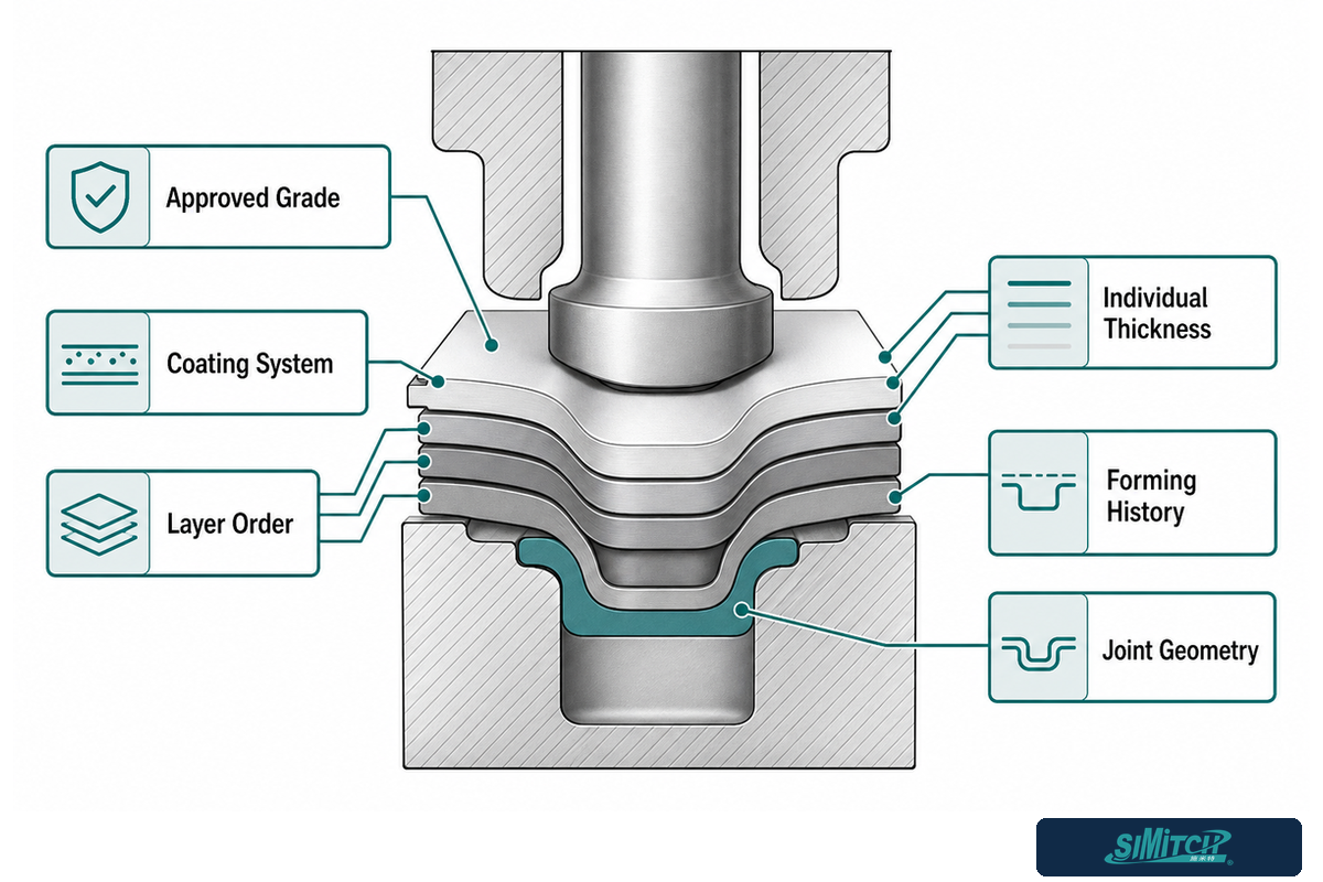
Begin with the mill designation or buyer-approved grade for every layer, its condition or temper, coating type and thickness if known, individual sheet thickness, total stack, and which layer faces the punch. Record prior forming history or work hardening near the joint, because bends and drawn regions may not behave like a flat coupon cut from unused sheet.
Current research does not support one universal thickness ratio or residual-bottom-thickness target. It does support the underlying mechanism: ductility differences and die geometry can change necking, cracking, and interlock formation, while small neck thickness and small undercut lead to different failure patterns. Tool design in the review is validated through experiments, not selected from total thickness alone.
In 2022, an open-access paper framed the same decision as a material-process-property chain. Its characterization plan spans sheet properties, friction in the joining system, the forming process, the resulting material structure, load-bearing behavior, degradation, and service life. This is a useful boundary for coated galvanized HVAC sheet and pre-painted appliance sheet: “the coating survived visually” is one observation, not the whole approval.
A practical stack record
Write “0.8 mm DX51D+Z punch side over 1.2 mm DC01 die side, coating retained, formed flange, drawing Rev C” instead of “2.0 mm galvanized stack.” The first description can be sampled and repeated; the second cannot.
US10328481B2 is a useful warning against universal tooling rules. It claims a 20–35-degree tapered-punch configuration for unequal-thickness appliance workpieces and names refrigerators, ovens, dishwashers, washers, and dryers. That proves one patented response to a defined geometry problem exists. It does not make that angle a default for another stack, die, or supplier.
Can the Punch and Die Reach Every Joint on the Formed Part?
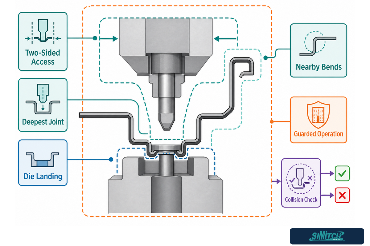
Draw the tool approach on the formed part, not on a flat blank. Mark the punch axis, die body, stripper, frame, nearest bend, return flange, obstruction, and operator or fixture path. Repeat that check at the first, deepest, and most restricted joint. One accessible corner doesn’t prove the rest.
Trade-press coverage states the basic boundary plainly: conventional clinching requires access to both sides of the joint. Sufficient throat depth and opening clearance must remain to place the part without collision. Nearby features can steal usable clearance even when the drawing’s nominal distance from the edge looks acceptable.
In 2025, an Airvent HVAC case showed what happens when this check comes late. Components originally designed for spot welding had narrow flanges; clinching needed a larger flange for the die landing, so the parts were redesigned. Airvent reported no material-yield loss in that case, but that result should not be generalized to another geometry.
Field signal: reach failed before force
Reach failed before force became the purchasing problem in a dated Practical Machinist discussion: the original poster focused on a roughly 12-inch horn needed inside the part. Treat that as experience, not a current price or specification. It still illustrates why a clearance drawing belongs in the RFQ.
For a US installation, access also includes the safeguarded operating condition. OSHA 1910.212 requires one or more methods of machine guarding to protect operators from point-of-operation hazards, ingoing nip points, rotating parts, and flying-object hazards, including flying chips or sparks. Any clearance concept that works only with a hand in the danger zone isn’t a viable production layout.
9-Input Configuration Disqualifier Map
Use this map before comparing model codes. “Disqualifier” doesn’t mean the application is impossible; it means the quoted configuration must change, be proven in a trial, or be replaced by another joining route.
| Input | Evidence to send | Disqualifier signal | Next decision |
|---|---|---|---|
| 1. Material identity | Grade, condition, certificate | Unknown ductility or mixed substitutions | Freeze approved materials before trial |
| 2. Surface system | Zinc, paint, film, oil, cosmetic face | Cracking, marking, slip, or finish rejection | Add surface acceptance and sample handling |
| 3. Layer thickness | Each layer plus total stack | Only a total value is supplied | Test the exact layer combination |
| 4. Sheet order | Punch side and die side | Order may change or is not controlled | Qualify every permitted order |
| 5. Joint load | Shear, peel/cross-tension, service direction | “Strong joint” with no load case | Define test orientation and failure rule |
| 6. Flange and edge space | Dimensioned landing, bends, nearby features | Die or stripper overlaps a feature | Redesign flange or tool package |
| 7. Tool access | Section view, deepest reach, required opening | Collision or one-sided joint | Change frame, sequence, or joining method |
| 8. Handling and duty | Part mass, orientation, joints/part, shift volume | Operator cannot present the part consistently | Add support, fixture, index, or automation |
| 9. Acceptance and traceability | Metrics, sample count, records, approver | No pass/fail owner or evidence package | Stop commercial comparison until defined |
Portable, Fixed Press, or Application-Built System?
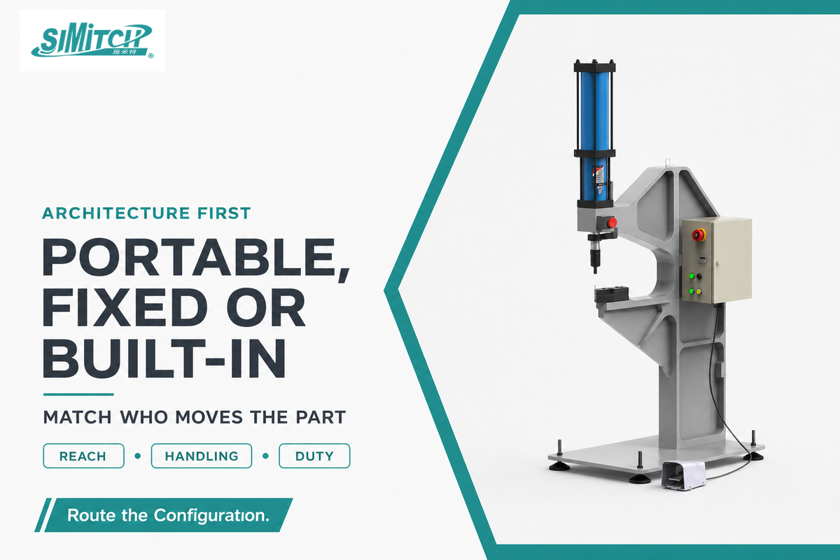
Choose the architecture around who or what moves the part. That choice starts with the reach and clearance limits mapped in the previous step. Portable clinching machines bring the tool to a large or awkward assembly. Fixed presses bring the part to a controlled station. Application-built systems add fixtures, indexing, multiple heads, or automated handling when joint pattern and duty justify the added scope.
| Record | Published boundary | What it helps screen | What it does not prove |
|---|---|---|---|
| CRH03 suspended hand tong | 45 and 75 kN classes; 40, 50, 60, 110, 160 mm reach options | Tool-to-part handling and reach | Your stack or joint strength |
| CEC universal press | 78 kN, 506 mm throat, 933 mm working height record | Fixed-station envelope | Clearance on a formed part |
| CEB bench family | Six load sizes, 18.4–283.6 kN | Load-class routing | Tool compatibility or duty |
| TCEU air-duct record | 78 kN and 400 mm throat | HVAC-oriented fixed arrangement | A new duct geometry |
| PC floor family | Seven load classes, 78–990 kN | Higher-load platform routing | That more force is preferable |
| Portable C/X concepts | Access configurations; no universal current material range published | Direction of approach and handling | A thickness or strength guarantee |
RFQ terminology that prevents mismatched quotes
Different suppliers use overlapping labels for equipment, tooling, and joint shape. Define the physical requirement beside each term so that wording does not hide a scope difference.
| Terms that may appear | What the RFQ should define |
|---|---|
| Clinch tooling; die and punch; punch tip radius; die blades | Drawing, revision, joint family, approved stack, maintenance limit, and replacement ownership. |
| Round joints; rectangular variant; dimple | Finished geometry, cosmetic face, load direction, and measurement method rather than a shape name alone. |
| Clinching force; tonnage; hydraulic drive | Available force at the tool, control method, approach speed, return behavior, and the tested process window. |
| Pneumatic or hydraulic; mounted clinching machines | Utility pressure/flow, intensifier or power unit, mounting reaction, duty, noise, and service access. |
| Portable tools; deep throat; 90-degree access | Part section, tool approach, usable opening, reach under load, balance, operator support, and pinch-point safeguarding. |
| Layers of sheet metal; stainless; dissimilar metal sheets | Every grade, condition, coating, individual thickness, total, and punch-side/die-side order. |
| Deformation; deform; distortion; clamp; vibration | Allowed part movement, local surface change, support points, reaction path, and post-joint dimensional check. |
| Pop failure; shear failure occurs | Test orientation, load curve, failure classification, sample count, and the rule for stopping production. |
| Metal joining; sheet metal joining; metal joining applications; automotive industry; HVAC components | The actual part, service load, cleanliness, surface, access, and production environment. Another sector’s use case does not qualify this application. |
| Clinching process; clinching systems; clinchers; cold-forming | Machine, head, tools, fixture, controls, data, sample method, and release boundary included in the quote. |
| Tool life; high-volume production; production needs; modular fixture | Validated life basis, inspection interval, change criteria, joints per shift, planned uptime, changeover modules, and spare strategy. |
| Precision; factors to consider; use cases; assess; pros and cons; cost-effective; versatility; choosing the right clinching route | Replace marketing adjectives with a value, tolerance, evidence source, owner, and pass/fail decision. |
BTM and Press Lock Technologies appear in the researched supplier-attributed trade coverage, including automotive and high-volume examples. They are company names, not neutral specifications. Any claimed production advantage still has to be demonstrated using the buyer’s part and accepted-joint criteria.
These records illustrate why “Pneumatic Clinching Machine” is still too broad a buying phrase. Pneumatic, pneumohydraulic, and servo-driven systems can each sit inside portable, fixed, or automated arrangements. Ask how force is produced and controlled only after part access and tool pairing are defined.
After the architecture is set, use the pneumatic and servo clinching press guide to compare drive and control boundaries, and the portable clinching machine maintenance guide to scope service access for a handheld route. Both pages support the next screen; neither replaces a part trial.
Use the current HVAC and home-appliance clinching application page to compare public project boundaries, then attach your own drawing and stack to the request. That page is a routing reference, not a sample approval.
How Should HVAC Duct and Damper Geometry Change the Choice?
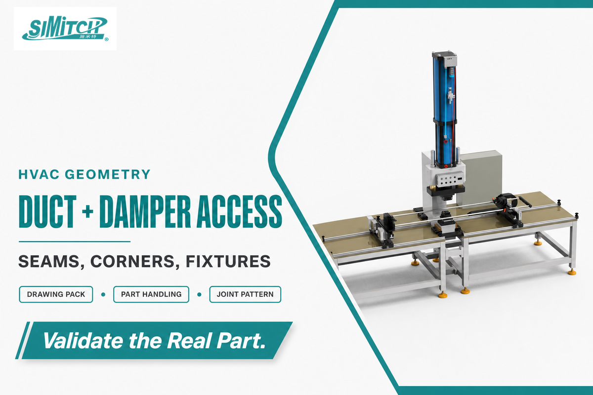
HVAC parts often combine long seams, curved or rolled bodies, corners, galvanized coatings, and large panels that are harder to present to a fixed throat. Those part shapes turn the architecture choice above into a handling and fixture decision. Separate the operation by joint pattern: a repeated seam, four damper corners, a rolled cylinder closure, or isolated bracket points don’t need the same fixture or head count.
Ahaus describes a damper cell that interfaces with two existing machines and clinches the overlapping sheet so the rolled cylinder stays fixed. Its value here isn’t an unspecified speed gain. Instead, the clinching station belongs inside a sequence with upstream and downstream interfaces.
SIMITCH publishes several distinct HVAC records: one TPC30 project lists galvanized or cold-rolled sheet, a supplier-published 0.5–2.0 mm range, and an under-8-second cycle boundary; a separate damper-corner platform lists an HZ29-50 working cylinder, HMPS200-2284 booster, four-point die, and a 2000 × 1200 × 800 mm supplied footprint. Those details belong to their recorded configurations. Every new damper still needs its own flange, reach, load, and acceptance review.
HVAC drawing pack
Include a section through the deepest joint, minimum and maximum duct size, seam orientation, corner sequence, coating face, unsupported panel span, joints per part, and the way the part arrives from the prior station. Flat coupons can’t answer these handling questions.
What Changes for Appliance Panels and Inner Tubs?

Appliance assemblies add cosmetic faces, mixed visible and hidden joints, drawn tubs, enclosed returns, and multiple station interfaces. Four-corner front-panel work in one fixture is a different problem from a dishwasher inner-tub assembly process that moves through forming, locating, clinching, inspection, and transfer sections.
SIMITCH’s public records describe a washing-machine front-panel project with four corners in one cycle and a dishwasher inner-tub concept split into five line sections with automated handling. No transferable strength or cycle guarantee is published for a new product. Use the examples to define fixture and sequence questions, then test the actual coated production sheet.
Cosmetic approval needs a named face and viewing rule. Record whether a button or ring may be visible, whether paint microcracks are allowed, and whether a local mark conflicts with a seal, liner, or trim part. Pair that surface review with joint measurements and load testing; neither replaces the other.
Do not generalize a patent example
Patent language in US10328481B2 shows why custom punch geometry may be developed for unequal sheet thickness. It is not permission to specify the patent’s angle or example load for a refrigerator, washer, or dryer without reviews covering licensing, tooling, and samples.
What Evidence Should a Sample Joint and Acceptance Plan Contain?
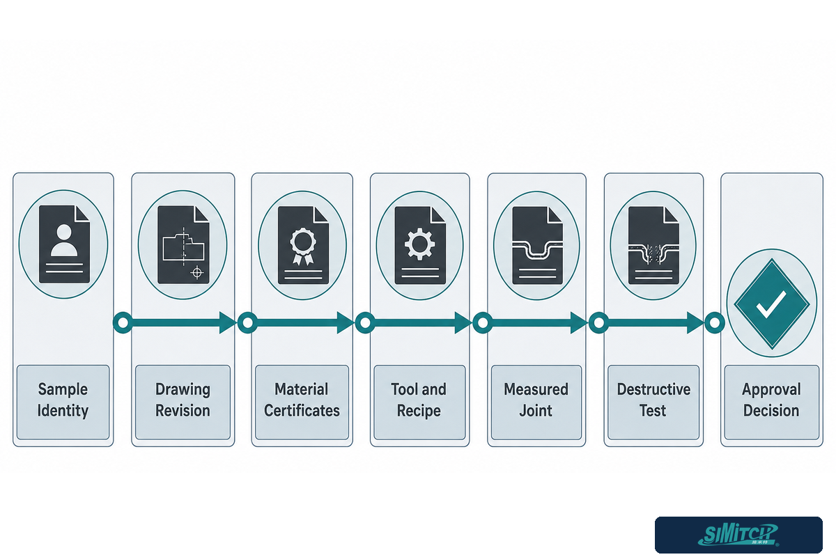
Give each sample an identity before it reaches the press. Its record should connect the drawing revision, material certificates, layer order, tool IDs, machine, recipe, operator or automation state, measured joint, destructive test, failure mode, and approval decision. Without that chain, a photo is hard to repeat.
ISO 12996:2013 specifies specimen geometry and the tensile-shear procedure for single mechanical joints on single-layer and multilayer specimens with an individual sheet thickness of up to 4.5 mm. ISO says the edition was reviewed and confirmed in 2024. It remains current, but it is a test-method standard. It does not certify a machine, set your minimum load, or approve a production part.
12-Field Sample-to-Acceptance Evidence Thresholds
“Thresholds” here means project-defined pass/fail values with an identified source. Where no approved value exists, the correct entry is “to be established by representative samples and engineering approval,” not a number copied from another machine.
| Field | Record | Threshold source | Release evidence |
|---|---|---|---|
| 1. Sample identity | Unique sample/lot ID | Trial plan | Traceable label |
| 2. Product definition | Part number and drawing revision | Released drawing | Signed revision record |
| 3. Material identity | Grade, condition, coating, certificates | Approved material specification | Certificate match |
| 4. Stack definition | Each thickness, total, punch/die order | Drawing and process sheet | Measured stack record |
| 5. Tool identity | Punch, die, stripper, revision | Approved tool list | Tool IDs and condition |
| 6. Process identity | Machine/head, recipe, force/displacement settings | Approved trial recipe | Locked recipe export |
| 7. Surface condition | Crack, mark, coating, visible face | Cosmetic standard | Controlled photos and verdict |
| 8. External geometry | Button diameter/height or approved gauge | Qualified sample study | Measurement data |
| 9. Bottom thickness | Measured residual value | Project trial, not a universal ratio | Gauge or section record |
| 10. Internal geometry | Neck thickness and undercut | Cross-section study and engineering rule | Section image plus measurements |
| 11. Mechanical result | Tensile-shear and any other required load modes or orientations; failure mode | Product engineering requirement and test method | Raw load curve and test report |
| 12. Production release | Sample count, capability/monitoring rule, deviation, owner | Control plan and approval matrix | Signed release package |
Bottom thickness, button diameter, neck, undercut, and test load are measurements, not automatic pass values. Establish limits based on the approved material range, tool combination, sample distribution, service load, and failure criteria. Re-run the study after a material, coating, tool, recipe, or drawing change that falls outside the qualified window.
How Do Utilities, Fixtures, and Automation Change the Machine Scope?
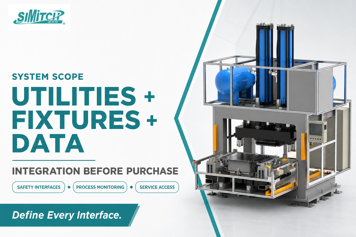
Request a utility and interface sheet before the purchase order. It should state compressed-air pressure and quality where relevant, electrical supply, control voltage, peak and average demand, cooling or lubrication needs, floor loading, working height, guarding concept, safety interfaces, exhaust or noise controls, network/data needs, and space for tool service.
Assembly Magazine’s 2025 expert interviews identify servo-electric drives, force/displacement monitoring, statistical process data, robot compatibility, compact units, and multi-station flexibility as current directions. The capability claims came from supplier representatives, so turn them into acceptance demonstrations: exported traces, reject handling, recipe permissions, communication test, and recovery after an interrupted cycle.
Integration questions that change the quote
- Who locates and supports the part while the reaction load is applied?
- What prevents a wrong part, stack, or orientation from entering the cycle?
- What’s recorded for every joint, part, batch, or sampled interval?
- How are a failed trace, double hit, missing hit, or tool-change condition contained?
- Which safety functions belong to the machine supplier, integrator, and plant?
This Ahaus damper example matters because the station connects to two existing machines. Interfaces between equipment packages are often where sensor signals, ownership, timing, and fault-recovery responsibilities go undefined. Put those interfaces on the line-layout and controls list before final pricing.
How Should You Compare Cost per Accepted Joint?
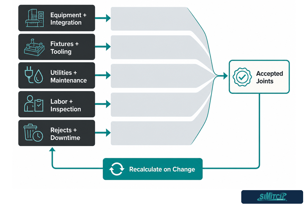
Searches for “clinching machine price” or “Clinching machines for HVAC & home appliance assembly price” skip the denominator that finance needs. The interfaces and utilities scoped above belong in that denominator. Compare annual cost per accepted joint, or cost per 1,000 accepted joints, with the same volume, yield definition, uptime boundary, labor scope, and validation plan for each joining option.
Use buyer-entered values for equipment and integration, fixtures, tools and spares, part redesign, utilities, planned maintenance, unplanned downtime, labor, inspection, destructive samples, rejected parts, and any separate rivet, screw, adhesive, or weld consumable. Divide by accepted joints, not machine strokes. If one option also provides a thread, seal, invisible surface, or one-sided access, price that function rather than pretending all joints are equivalent.
A favorable case is not an automatic result
Airvent reported a 15% average production-speed increase and up to 30% in some cases after moving selected HVAC work from spot welding to clinching. Those are company-reported results from one production context. That same case also records a flange redesign, whose cost and scope belong in another plant’s comparison.
SIMITCH’s public cost-per-accepted-joint comparison intentionally uses buyer inputs rather than a universal return-on-investment claim. Re-run the worksheet with verified quotes and measured first-pass yield during the sample program.
Worked example: normalize the inputs before comparing quotes
The values below are fictional buyer inputs, not SIMITCH machine specifications or recommended acceptance limits. Their purpose is to show the level of detail that keeps two supplier quotes comparable; replace every example with project data drawn from your part drawing, production study, plant standard, and approved sample results.
| Input field | Fictional worksheet value | What the buyer must verify |
|---|---|---|
| Outer sheet | 0.8 mm coated steel | Grade, coating, hardness, and tolerance |
| Inner bracket | 1.0 mm aluminium | Alloy, temper, and punch/die order |
| Nominal stack | 1.8 mm total | Minimum and maximum stack tolerance |
| Available flange | 18 mm | Die body, support, and drawing clearance |
| Proposed joint center | 9 mm from the edge | Trial result and drawing approval |
| Deepest reach | 145 mm | Tool path and frame deflection at the actual point |
| Required opening | 42 mm | Loading path, fingers, fixtures, and withdrawal |
| Part envelope | 620 mm × 410 mm × 85 mm | Rotation, obstruction, and collision study |
| Part mass | 3.2 kg | Operator handling or fixture requirement |
| Shift basis | 480 parts per 8 hr | Breaks, changeovers, planned stops, and mix |
| Line takt | 60 sec per part | Number of joints and permitted process time |
| Air available | 0.6 MPa at the connection | Pressure under peak demand, quality, and consumption |
| Electrical supply | 400 V, 50 Hz | Plant standard, protection, and control voltage |
| Connected load | 2.2 kW | Peak and average demand from the supplier quote |
| Tool-change allowance | 15 min | Observed change, verification, and restart sequence |
| Sample-record retention | 30 days | Customer, quality-system, and traceability requirements |
| Spares planning horizon | 12 months | Wear study, lead time, and local stock policy |
| Illustrative first-pass target | 85% | Replace with the buyer-approved yield definition |
Attach the completed input sheet to the request for quotation. If a supplier changes the sheet order, tool geometry, frame, drive, fixture, monitoring scope, or acceptance method, treat it as a different configuration and recalculate the comparison rather than carrying the old cost-per-joint result forward.
When Is Clinching the Wrong Joining Process?
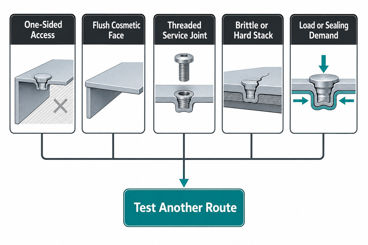
Clinching may be the wrong route when the tool can’t reach both sides, the surface must remain flush or invisible, the material can’t form without cracking, the flange can’t provide a die landing, or the tested interlock cannot provide the required load capacity or sealing function. Very small lots may also favor lower-capital hardware insertion, while a screw, nut, rivet, adhesive, or weld may provide a function that clinching doesn’t.
That feasibility screen comes before the cost-per-joint calculation above. Tip maintenance interrupted production often enough to change the joining method in one practitioner account, but that doesn’t make clinching the default replacement. An adapted press-brake holder and backgauge changed the equipment architecture in the same discussion. Compare feasible process routes on the actual part instead of swapping one generic machine for another.
| Requirement | Route to test beside clinching | Reason |
|---|---|---|
| One-sided access | Blind rivet, screw, adhesive, redesigned sequence | Conventional punch/die pair cannot reach both sides |
| Flush cosmetic face | Spot weld, adhesive, hidden fastener | Clinched button/ring may remain visible |
| Thread or removable service joint | Inserted hardware or screw | Fastener supplies a separate function |
| Unqualified brittle/hard stack | Weld, rivet, adhesive, local process development | Forming may crack before interlock develops |
| Ultimate-load or sealing demand | Weld, rivet, adhesive, hybrid joint | Product test may need another load path or seal |
Frequently Asked Questions
What is a clinching machine?
Clinching machines use a matched punch and die to form overlapping sheet layers into a local mechanical interlock in one cold-forming stroke without adding a separate fastener.
Machine motion creates the joint, while the approved sheet stack, punch, die, access, and process setting define whether it is acceptable. Portable, fixed, and automated architectures can all use this forming principle. Approval applies only to the exact part and test plan, so a family name or rated load cannot replace sample measurements and the required mechanical test.
What materials and thickness ranges can a clinching tool handle?
There is no universal range across all tools and machines. Specify each material grade, coating, individual thickness, total stack, and punch/die order for a representative trial.
Ductility, thickness ratio, previous forming, friction, punch geometry, die radius, die depth, groove design, and the direction of material flow can change the result. Coated and pre-painted sheet also needs a surface review after forming. Treat every published range as a configuration boundary until samples from the allowed production material window have been measured, mechanically tested, and released by the named approver.
How much throat depth does a clinching machine need?
The required throat depth must provide enough usable reach for the deepest joint after the die, stripper, frame, fixture, nearby bends, guarding, and part-loading path are included.
Draw a section through the formed part and check the complete loading and tool motion. Catalog throat depth is only one input: the opening, die body, stripper, fixture, return flange, nearby bend, operator support, and safeguarded path all consume clearance. Verify the first, deepest, and most restricted joint rather than measuring from one easy edge.
What is the total stack thickness to be joined?
Total stack thickness is the sum of all layers at the joint, but that number alone cannot select or qualify a tool for the actual material combination.
Record every layer separately, including its grade, condition, measured thickness, coating, and position on the punch or die side. Two stacks with the same total can form different necks and undercuts when their ductility, thickness ratio, friction, prior forming, or order changes. If production permits material substitutions or reversed assembly, qualify each allowed combination and link it to the corresponding tool and recipe.
Does the application require shear resistance, peel strength, or both?
Name every load direction the joint sees in service and test the relevant orientation; a tensile-shear result alone may not represent peel or cross-tension behavior.
Define the specimen, load direction, result, failure mode, and approver. ISO 12996 provides an in-scope tensile-shear procedure but does not set your product limit.
Why We Write This
Suzhou Simitch Machinery Co., Ltd. develops clinching, riveting, servo-press, pneumohydraulic, and automated joining systems for industrial sheet-metal assembly. This guide separates public configuration records from application proof so engineers, production teams, and buyers can send comparable evidence to every supplier.
Updated August 2026.
References & Sources
- ISO 12996:2013, Mechanical joining — Destructive testing of joints — International Organization for Standardization
- Clinching for sheet materials — peer-reviewed open-access review
- Clinching of Aluminum Materials: Process, Microstructure and Properties — Journal of Advanced Joining Processes
- 29 CFR 1910.212, General requirements for all machines — US Occupational Safety and Health Administration
- Sheet metal clinching 101 — The Fabricator
- Spot weld, fasten, or clinch? — The Fabricator
- Clinching Improves Sheet Metal Assembly — MetalForming Magazine
- What’s New With Clinching — ASSEMBLY Magazine
- US10328481B2, Clinching punch and apparatus — Google Patents record
Prepare a Comparable Clinching RFQ
Use the SIMITCH HVAC and home-appliance application page for a configuration review, then attach the nine disqualifier inputs and twelve acceptance fields from this guide. Engineering can then start from the part and evidence package rather than a model guess.
![Hot-Melt Connection Molds & Equipment Guide [2026]](https://simitch.com/wp-content/uploads/2026/09/hot-melt-connection-molds-equipment-guide-featured-768x512.png)