Get in touch with Suzhou Simitch Machinery Co., Ltd Company

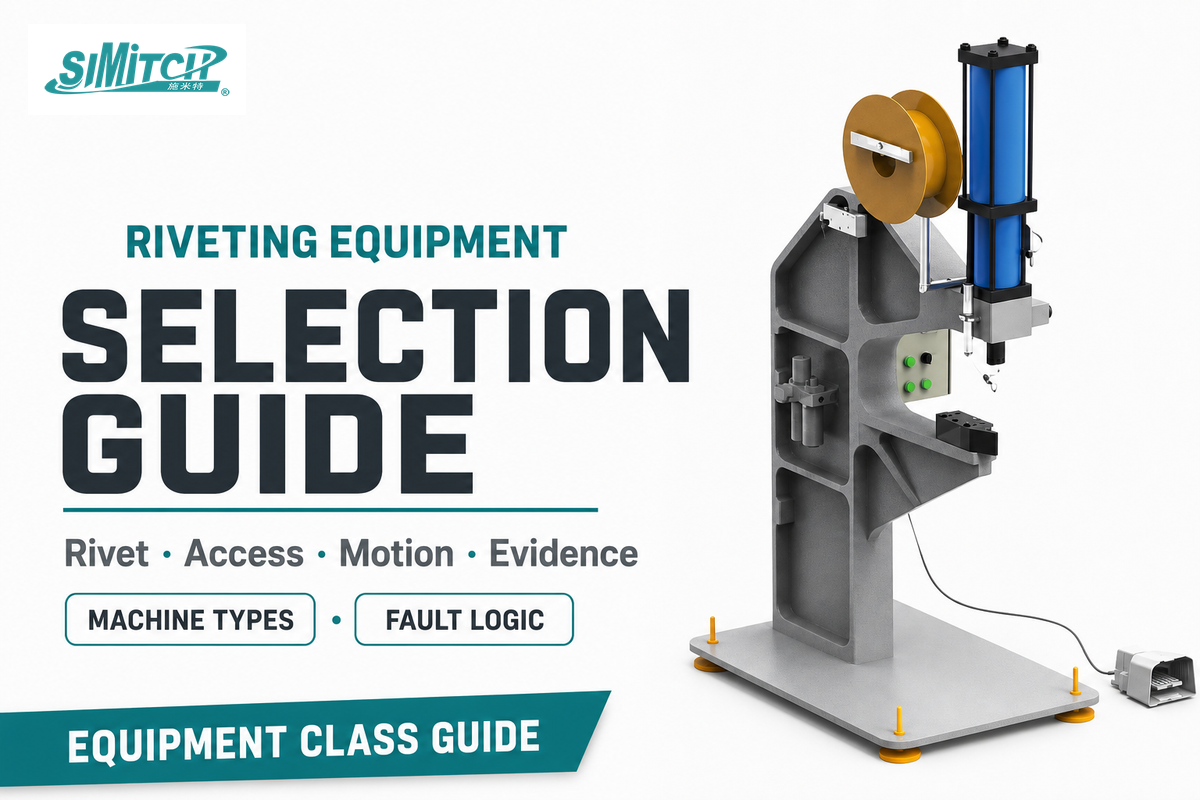
Riveting equipment is not one machine category. Hand riveters, orbital riveters, blind-rivet tools, and self-piercing cells may all make permanent mechanical joints, yet they load the fastener, support the work, and verify the result in different ways. Ask first, therefore, not “Which model has enough force?” but “Which rivet, access condition, forming motion, feed scope, and evidence requirement define this joint?”
This guide answers that equipment-class question. It deliberately stops before supplier-specific configuration, pricing, or quotation, which remain the job of the commercial solution page.
What Counts as Riveting Equipment?
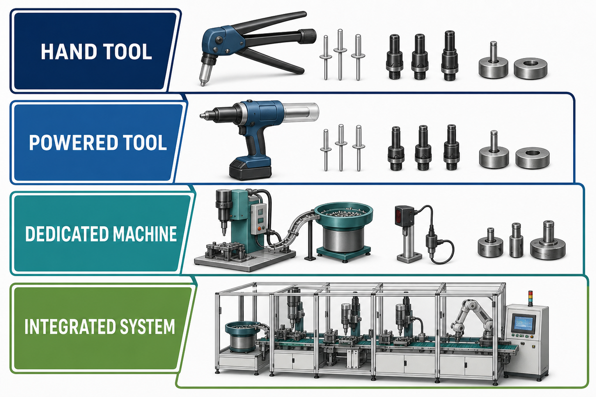
Within that equipment-class boundary, production scope begins when the process depends on controlled work support, repeatable tooling alignment, material presentation, or recorded process evidence. Power alone is a poor boundary: a portable pneumatic riveter can remain operator-controlled, while a modest bench machine may include fixtures, interlocks, and a defined acceptance routine.
| Equipment class | Common search label | Work support | Scope boundary |
|---|---|---|---|
| Hand setter | Manual riveting kit | Held by operator | Repair, prototypes, low volume |
| Lever or squeeze tool | Heavy-duty hand riveter | Operator supplies reaction | Accessible repeat work |
| Battery tool | Battery pop rivet gun | Operator and nosepiece | Portable blind-rivet setting |
| Pneumatic tool | Pneumatic rivet gun | Operator or bucking support | Powered portable work |
| Rivet-nut setter | Rivet nut tool | One-sided screw mandrel | Threaded-insert installation |
| Impact machine | Impact riveting machine | Defined anvil or fixture | Short axial forming event |
| Orbital or radial machine | Orbital riveting equipment | Fixture plus reaction member | Progressive head forming |
| Squeeze press | Riveting press | Opposed tooling | Two-sided sheet metal joints |
| Self-piercing cell | SPR system | Punch, die, and frame | Validated sheet-stack application |
| Automatic feed cell | Automatic riveting system | Fixture and part handling | Manufacturing automation and traceability |
Search labels are not an engineering specification. Aircraft and aerospace work, automotive assembly, aluminum rivets, or an electrical enclosure may each lead to different setting tools, accessory choices, rivet diameter, head or snap profile, shaft geometry, mount, offset, motor, adjustable stroke, force required, tray or feeder, and cycle-time target; the actual drawing and validation plan decide which terms matter.
The industry also uses overlapping discovery labels: riveting press machine, pneumatic rivet machine, industrial rivet machine, self-piercing riveting machine, automated riveting equipment, and orbital riveting machine. Queries such as professional riveting equipment, riveting equipment for metal, or heavy-duty riveting equipment still require the same joint-first check; they are not separate types of riveting process.
Manual and semi-automatic choices also belong inside the site’s exposure-control program. NIOSH identifies riveting as a noise-generating task and recommends comparing tool noise on a consistent measurement basis, while its hand-arm vibration criteria cover both handheld tools and stationary tools that transmit vibration through the workpiece. Record measured exposure and the site’s controls instead of treating a quieter catalogue label as proof of compliance.
If the real decision is whether to rivet, weld, bond, or mechanically fasten, first compare metal joining methods. This article assumes riveting is already a credible process family.
Start With the Rivet
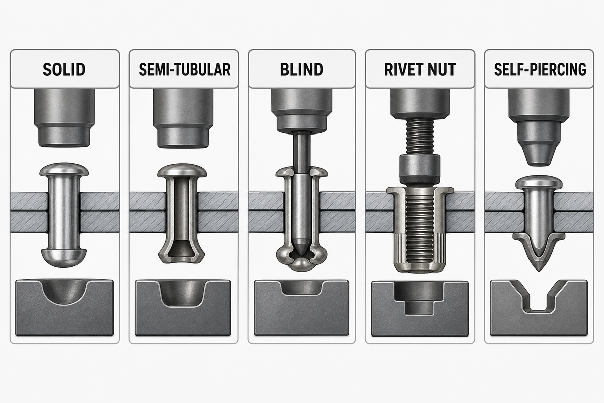
Fastener construction defines the setting action. Solid and semi-tubular rivets usually need a forming tool on one side and reaction support on the other. Blind rivets create their reaction through a mandrel from the accessible side. Rivet nuts deform to create a threaded insert, while self-piercing rivets join sheet stacks without the prepared hole required for conventional rivets.
| Family | Access | Setting action | Early evidence |
|---|---|---|---|
| Solid | Usually two-sided | Upset tail against support | Head and upset geometry |
| Semi-tubular | Usually two-sided | Roll or flare hollow end | Flare, clamp, damage check |
| Blind | One-sided | Pull mandrel to form blind head | Head seating and mandrel event |
| Rivet nut | One-sided | Collapse body into threaded insert | Set geometry and thread function |
| Self-piercing | Tool and die access | Pierce upper sheets and flare in die | Process trace plus joint checks |
For self-piercing and other mixed-material joints, the selector starts only after stack sequence, material ductility and thickness, die geometry, and rivet properties make the joint feasible. A peer-reviewed SPR review reports that joinability and interlock requirements depend on the stack and materials, so no universal interlock value can qualify every joint. Access comes before machine type only after this joint-stack screen.
For the last family, review the boundaries of self-piercing riveting machine families only after confirming material stack, access, and die-side support.
One-Sided or Two-Sided Access Comes Before Machine Type
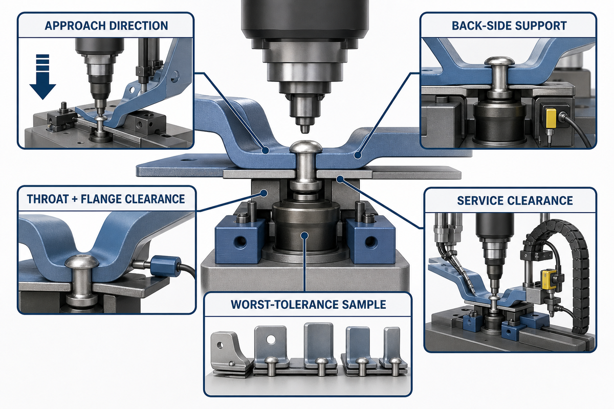
Ample rated capacity cannot compensate when the nose, die, anvil, throat, or fixture cannot reach the joint. Check the complete assembly, not an isolated coupon. Flanges, adjacent walls, clamps, robot wrists, operator hands, and service access all consume the envelope around the rivet.
An industrial review of orbital and radial forming explicitly separates processes that need access to both assembly sides from blind riveting. Treat reach as a process boundary before comparing machine size, drive efficiency, or force.
Access-envelope worksheet
- Mark every permitted tool approach direction.
- State whether a reaction tool or die can reach the back side.
- Record throat depth, flange clearance, and fixture obstruction from the production drawing.
- Check loading, unloading, maintenance, and tool-change clearance.
- Test the worst-tolerance sample, not only the nominal part.
Use the 7-Motion Riveting Map Before Choosing a Drive
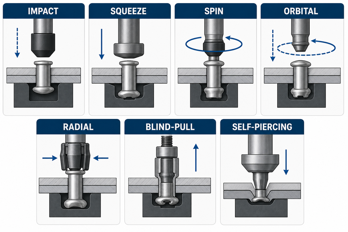
Once the access envelope is viable, forming motion describes how the tool deforms or sets the fastener. Pneumatic, hydraulic, mechanical, or servo drive describes how the machine produces and controls that motion. Mixing these axes creates false comparisons such as “orbital versus hydraulic,” even though an orbital head can be driven in more than one way.
| Seven-Motion Riveting Map | Tool path / reaction | Useful when | Watch first |
|---|---|---|---|
| Impact | Axial blow | Short forming event is acceptable | Shock, support, surface marking |
| Squeeze | Opposed compression | Both sides are accessible | Reaction structure and reach |
| Spin | Rotating axial tool | Rotational forming suits the head | Heat and surface condition |
| Orbital | Tool axis inclined around center | Progressive head forming is desired | Tool path and alignment |
| Radial | Rosette-like radial path | Controlled local forming is required | Path definition and tooling |
| Blind-pull | Mandrel creates blind-side reaction | Only one side is reachable | Nosepiece, grip range, mandrel handling |
| Self-piercing | Punch and die form an interlock | Defined sheet stack supports the process | Die, stack, alignment, trace correlation |
Match the Tooling and Work Support to the Joint
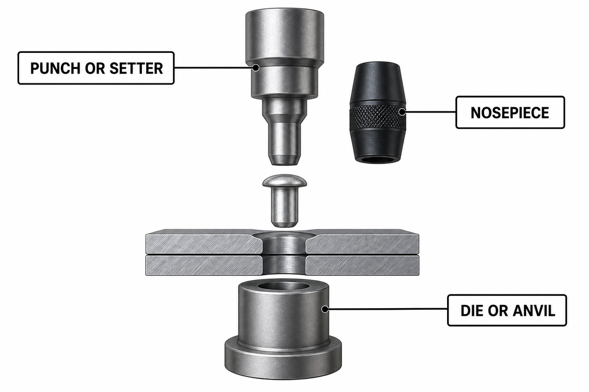
No machine drive can rescue a poor tooling stack. Record the punch or setter, die or anvil, nosepiece, rivet guidance, fixture datum, reaction member, and replaceable wear surfaces as separate items. This makes it possible to distinguish a machine-control problem from a worn nosepiece or moving work support.
A trade-press maintenance guide traces alignment errors to the fixture, part, or machine setup and treats tooling length, wear, lubrication, air pressure, and air volume as separate checks. That is why production troubleshooting should preserve the tool ID and fixture condition instead of changing the drive setting first.
Do not tune around wear. If an operator increases force or stroke to compensate for damaged tooling, the apparent fix can hide the original cause and move damage into the workpiece.
Separate Rivet Setting From Feeding and Automation
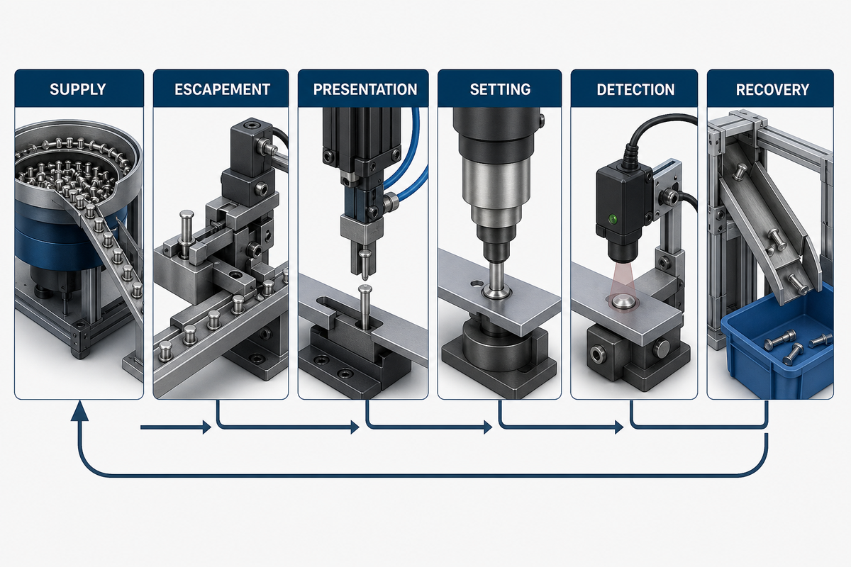
Setting the rivet is only one segment of an automated cycle. Waiting for a rivet, incorrect presentation, a failed part-presence check, or long manual recovery can still dominate output. Supplier cycle claims are therefore incomplete unless their start and stop points, fault assumptions, and recovery policy match the buyer’s process.
“When a manufacturer switches from fully manual to fully automated riveting, part fixturing is often a greater challenge than the actual riveting.”
Automation Hidden-Bottleneck Map
- At supply, can the feeder maintain orientation without starving?
- At escapement, is exactly one fastener released?
- During presentation, does the rivet reach the joint in the required orientation?
- Setting: Does the selected motion complete within its validated window?
- Detection: Are part, rivet, mandrel, and process-result states distinguished?
- Recovery: Can the cell clear a fault without losing part identity or recipe control?
For a process-data example, see how servo riveting assembly systems separate controlled motion from the surrounding cell requirements.
Decide What Process Evidence the Machine Must Produce
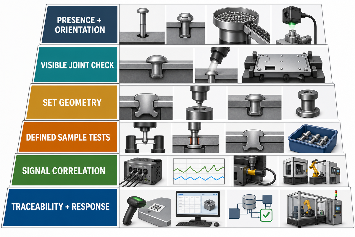
Monitoring is not the same as acceptance. Force-displacement traces, stroke values, presence signals, or mandrel events become useful only after they are related to a defined joint, a reference test, and a reaction rule. Evidence depth should match the consequence of a bad joint.
Evidence ladder
- Presence and orientation confirmation.
- Visible head, seating, and damage checks.
- Measured set geometry or functional checks.
- Sectioning or destructive tests on defined samples.
- Correlation of production signals with accepted and rejected joints.
- Traceability, alarm limits, and a documented containment response.
Do not borrow a universal threshold from another fastener or sheet stack. ISO test scope and published monitoring research support a method of correlation, not a single acceptance number for every riveting process.
Static geometry or tensile-shear evidence does not establish service life by itself. A review of cold-riveted double-shear lap joints found that cladding, anodizing, drilling, residual stress, riveting, and interface friction can affect fatigue response; its application scope is not transferred as a universal test plan. Add fatigue, corrosion, environment, and surface-treatment validation when the service requirement makes them relevant.
Use the Rivet–Access–Motion Selector
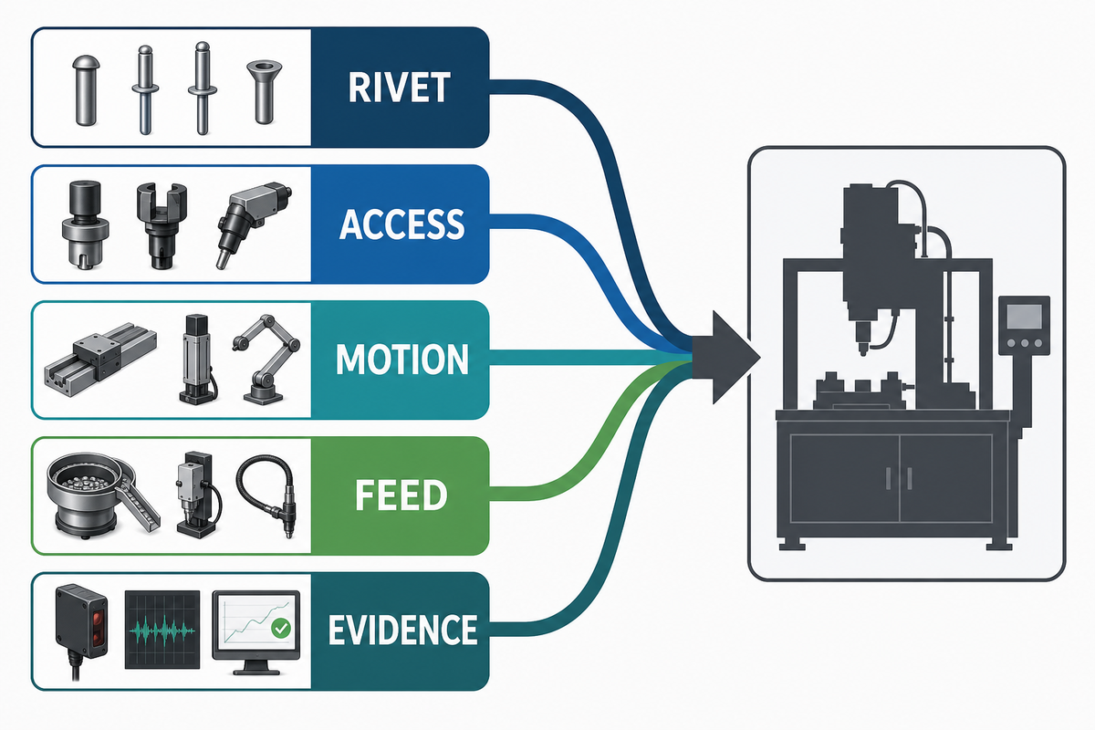
The Rivet–Access–Motion Selector produces an equipment class, not a model. Complete its rows in order because the fixed fastener and physical access eliminate infeasible motions before feed, control, or evidence options are compared. The result is a bounded shortlist for engineering review.
| Input | Decision question | Output |
|---|---|---|
| 1. Rivet | What fastener family and set geometry are fixed? | Feasible setting actions |
| 2. Access | Can both tool and reaction member reach? | One- or two-sided class |
| 3. Motion | Which forming path fits finish, support, and joint behavior? | Mechanism shortlist |
| 4. Feed | Manual load, assisted feed, or integrated automation? | Machine/system scope |
| 5. Evidence | What must be checked, correlated, and traced? | Control and validation scope |
Check the completed five-row output against a system comparison explorer before any supplier-specific configuration discussion.
Diagnose Bad Joints With the Five-Origin Fault Ladder
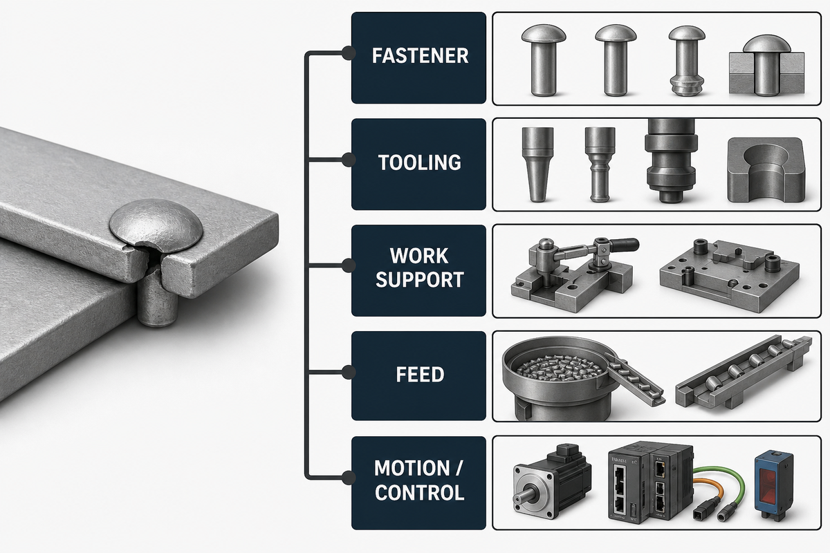
After the selector produces a shortlist, similar joint symptoms can still come from different origins. An incomplete head may reflect the wrong rivet, worn tooling, a moving fixture, inconsistent feed, or a changed motion recipe. Change one layer at a time and compare it with the last known-good sample.
| Five-Origin Riveting Fault Ladder | Check first | Evidence to preserve |
|---|---|---|
| 1. Fastener | Family, dimensions, lot, orientation, surface | Lot and sample |
| 2. Tooling | Setter, die, nosepiece, wear, contamination | Tool ID and condition |
| 3. Work support | Datum, clamp, alignment, deflection | Fixture and part position |
| 4. Feed | Orientation, escapement, transfer, presence | Fault sequence and rejected rivet |
| 5. Motion/control | Recipe, stroke, force, speed, sensor state | Trace and change history |
Use a riveting maintenance milestone planner to turn recurring observations into planned checks rather than emergency adjustments.
When Is the Decision Ready for Engineering Review?
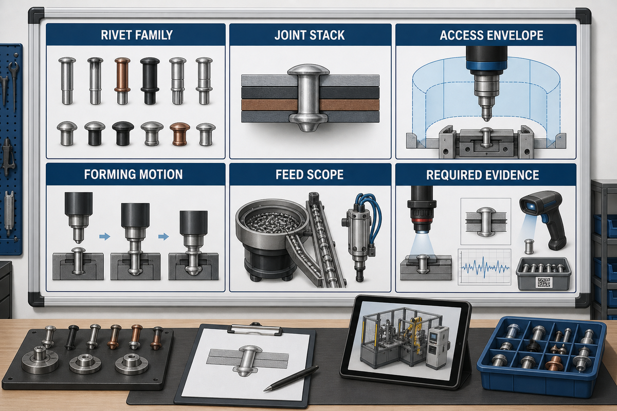
With the recurring fault layers defined, move to a supplier-specific engineering review when six items are stable: rivet family, joint stack, access envelope, preferred forming-motion shortlist, loading or feed scope, and required evidence. Bring drawings, the sample-acceptance method, and representative parts, including the worst access and tolerance conditions.
| 9-Field RFQ Measurement Map | Record from drawing or validated trial | Why it matters |
|---|---|---|
| Rivet diameter | mm | Nosepiece, hole, and tooling match |
| Joint stack | mm by layer | Grip range and process feasibility |
| Throat depth | mm | Reach to the joint center |
| Approach offset | mm | Clearance around walls and clamps |
| Stroke window | mm | Validated start and end conditions |
| Clamp or reaction force | N | Fixture and frame requirement |
| Setting force required | N | Drive and tooling trial input |
| Complete cycle time | s | Includes load, detect, set, and recover |
| Utilities and footprint | bar, V, kW, and mm | Plant integration boundary |
Do not fill these fields with catalogue maxima or a convenient round number. Record the measured requirement, tolerance, test method, and sample identity so engineering can assemble a reproducible trial and compare equipment on the same basis.
Handoff boundary: the guide identifies the equipment class. Engineering still has to validate tooling, fixture reaction, process window, sample acceptance, controls, safety integration, and commercial scope. Continue to industrial riveting equipment solutions only when those inputs are ready.
Frequently Asked Questions
These answers clarify terms that often surface while a team prepares the measured inputs and engineering-review package described above.
What are riveting tools?
Riveting tools deform or set a rivet to make a permanent mechanical joint. The category ranges from hand tools and powered guns to presses, orbital heads, blind-rivet setters, and integrated systems. Choose the label from fastener, reaction method, work support, and process control.
Can I install rivets without a rivet gun?
Sometimes. Hand tools, presses, squeeze tools, hammer-and-bucking arrangements, orbital or radial machines, and purpose-built automated heads can all set certain rivets. Acceptability depends on rivet construction, access, finish, consistency, and the evidence required from the joint. Confirm the method on representative parts before release.
What are the three types of rivets?
There is no universal three-type classification. Rivets may be grouped as solid, semi-tubular, tubular, blind, drive, rivet nuts, or self-piercing, with further variants inside each family. Those families can be divided again by head, body, material, grip range, or installation method. Grip length, coating, hole preparation, and service load create further application-specific distinctions. For equipment selection, use the actual fastener drawing and setting method instead of forcing the joint into a simplified three-item list.
Is orbital or radial riveting better?
Neither is universally better. Orbital motion carries an inclined tool axis around the rivet center, while radial forming follows a different local path. Those paths influence tool contact, finish, alignment sensitivity, and how deformation develops through the head. Compare them on the real fastener, supported workpiece, and target geometry rather than on a mechanism label. Keep the fixture, fastener lot, and acceptance method constant so the trial isolates the forming path. Document the resulting process window as well.
A useful sample review compares head shape, workpiece marking, joint function, process stability, and tool condition. If either option needs different support, include that change; the better choice has a validated process window and maintainable tooling for the actual assembly.
Does every riveting machine need access to both sides?
No. Blind rivets and rivet nuts allow one-sided installation; many other processes need back-side reaction, an anvil, or die access. Check the complete part and fixture because walls, clamps, loading motion, maintenance clearance, and the reaction tool can each remove an apparently open approach path.
How do you know a rivet was set correctly?
Start with presence, seating, visible damage, and set geometry. Higher-risk joints may require functional tests, sectioning, destructive tests, or production-signal correlation. Treat a machine trace as acceptance evidence only after connecting it to validated joint results and a defined containment response. The control plan should also name the sample frequency, measurement method, record owner, alarm limit, reaction step, and product-containment boundary. Preserve rejected samples and trace records so later drift can be compared with the original approval basis.
How This Guide Was Built
Suzhou Simitch Machinery Co., Ltd. publishes this guide to separate equipment-class education from supplier configuration. The taxonomy and decision tools synthesize public technical research, standards scope, current search intent, and observed production-system dependencies; no universal force, thickness, cycle, or acceptance value is claimed.
References & Sources
- ISO 12996 — Mechanical joint testing scope
- NASA Fastener Design Manual record
- Publicly archived riveting process-monitoring research
- TWI guidance on monitoring self-piercing riveting
- Orbital and Radial Forming
- Automating the Riveting Process
- Self-piercing riveting failures, corrosion, and optimization review
- Riveting-process parameters and fatigue-life review
- NIOSH engineering controls for noise
- NIOSH hand-arm vibration criteria