Get in touch with Suzhou Simitch Machinery Co., Ltd Company

Clinching Machines for HVAC & Home Appliance Assembly
Clinching machines for HVAC and home appliance assembly must match the formed part, material stack, joint pattern and acceptance evidence before the equipment scope is locked. SIMITCH designs fixture-based, multi-point and automated systems for HVAC dampers, washing-machine panels, dishwasher inner tubs and other sheet-metal assemblies.
Clinching here means fastener-free cold forming
A punch and die form a mechanical interlock without adding a rivet, nut or welding heat. This process differs from self-piercing riveting, blind riveting, clinch-nut insertion and resistance spot welding.
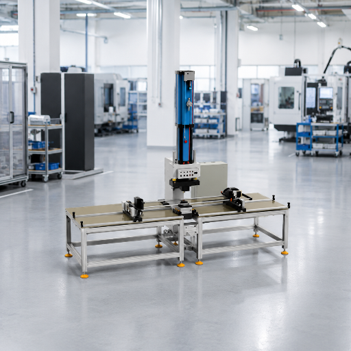
5 documented applications
HVAC damper, washing-machine, dishwasher and integrated-stove equipment from supplied project materials.
Actual formed samples
Flat coupons do not capture every bend, coating, tolerance or prior-forming effect.
9 evidence gates
A visible decision path exposes the hidden constraint before equipment selection.
No universal ROI claim
Cost per good joint is calculated only from the buyer’s own process and production inputs.
When a Standard Clinching Press Does Not Match the Assembly
A machine can apply force yet still fail if the punch and die do not reach the actual flange or throat depth. Nominal grade and final thickness may also obscure prior forming strain that influences material flow and joint geometry.
The Common Assumption
“The sheet fits the stated thickness range, so the joint is qualified.” Not necessarily true for bends, coating, layer order, access, alignment and service duty that differ from the test piece.
Decision Gate
The trade-off is clear: a press that reaches nominal force can still be the wrong choice when access or the acceptance plan remains unproven. Review the formed part before selecting the frame.
01
Tool Access
Workpiece geometry must allow the punch, die, frame and fixture to reach each joint without collision or cosmetic damage.
02
Material History
A flat substitute will not replicate a stamped, rolled or bent production part even when finished thickness is identical.
03
Coating and Stack
Coating, mixed materials and service exposure can alter retained joint strength, so an initial button formation only represents one data point.
04
Fit-up and Alignment
Sheet tolerance, tool alignment and layer placement can alter neck thickness and interlock within the same nominal design.
05
Functional Duty
A visually formed button is not proof of vibration, peel, leak, torque or duty cycle performance in the final assembly.
06
Scope Ownership
A custom-machine quote can look complete while guarding, control interfaces, the document set, FAT evidence and SAT ownership remain open.
07
Search-label Ambiguity
Sheet metal clincher, sheet metal clinching machine, clinching machine for sheet metal, and clinching tools are search terms; they don’t provide enough information to choose the equipment. Buyers use metal joining and sheet metal fastening for this and many related purposes.
Match the Clinching Machine to the Part and Joint Pattern
A long damper blade, four-corner front panel and multi-station dishwasher tub require different machine architectures. Start with a work sequence proven on representative parts, then choose the lowest-complexity configuration that can hold access, repeatability, takt and changeover.
The Evidence-Gated Part-to-Press Selection Matrix
The Evidence-Gated Part-to-Press Matrix is a SIMITCH buyer method, not an industry standard. It prevents one unresolved input from being hidden inside a larger press, a stronger cylinder or a more automated line. SIMITCH will not claim that clearing one gate qualifies the other eight.
Gate
Evidence Required Before Selection
Typical Hidden Bottleneck
Decision Output
1
Process Family
Required joint type, added-fastener policy, heat limits and visible-surface requirement.
The RFQ says “riveting” while the part actually needs fastener-free clinching or a threaded insert.
Clinching, SPR, blind rivet, clinch nut, spot welding or another route.
2
Actual Material Stack
Grade, temper, thickness for every layer, coating, layer order and allowed marking.
A nominal thickness range hides ductility or coating behavior.
Proceed to sample tooling, revise stack or reject the process.
3
Forming History
Representative stamped, bent or rolled samples and the operation sequence before clinching.
Flat coupons do not reproduce the production material state.
Approve the actual part window or request a process change.
4
Access And Joint Pattern
3D model, drawing, joint coordinates, edge clearance, throat depth and cosmetic sides.
The frame or die cannot reach one joint without collision.
Single-point, multi-point, fixture, index or robotic concept.
5
Joint Geometry
Sectioned samples, bottom thickness, neck thickness, interlock and visual criteria.
A button forms but alignment or sheet variation reduces interlock.
Tool geometry, sensor, fixture and process-window definition.
6
Service Duty
Static, peel, fatigue, vibration, corrosion and temperature requirements where relevant.
Initial strength passes while service exposure changes retained load.
Test plan, material/coating decision and maintenance checks.
7
Functional Acceptance
Leakage, pressure drop, torque, noise, closure, fit or customer-specific product tests.
Joint strength does not prove the assembled product’s function.
Part-level and product-level acceptance criteria.
8
Takt And Variants
Required cycle, daily mix, operator work, changeover method, buffer and fault recovery.
Nominal cycle omits loading, inspection, changeover or restart losses.
Manual, fixture-based, indexed or integrated automation boundary.
9
Integration And Responsibility
Utilities, controls, guarding, interfaces, manuals, FAT, SAT and site responsibilities.
A low machine price excludes the work needed for safe production acceptance.
Comparable quotation and signed responsibility matrix.
Research Example: Prior Forming
One controlled study reported joint loads of 608 N, 645 N, 671 N and 712 N at 0%, 20%, 47% and 60% prior thickness reduction in its tested AA6060 setup. Those values show sensitivity; they are not transferable design values.
Research Example: Exposure
A separate study used 1,176 hours of salt-spray exposure and found condition-dependent retained-load changes across tested material and coating combinations. It does not establish a service-life percentage for SIMITCH equipment or another joint stack.
Test-Scope Boundary
ISO 12996:2013 describes tensile-shear testing for single mechanical joints with each sheet up to 4.5 mm, and the ISO record shows confirmation in 2024. It is a test basis rather than product certification.
Validation
Clinching vs Spot Welding — A Part-Validation Decision
The honest version is that clinching is not always better than spot welding, and spot welding is not always the safer production choice. Material pairing, coating, access, surface appearance, load path, volume and process controls decide the route.
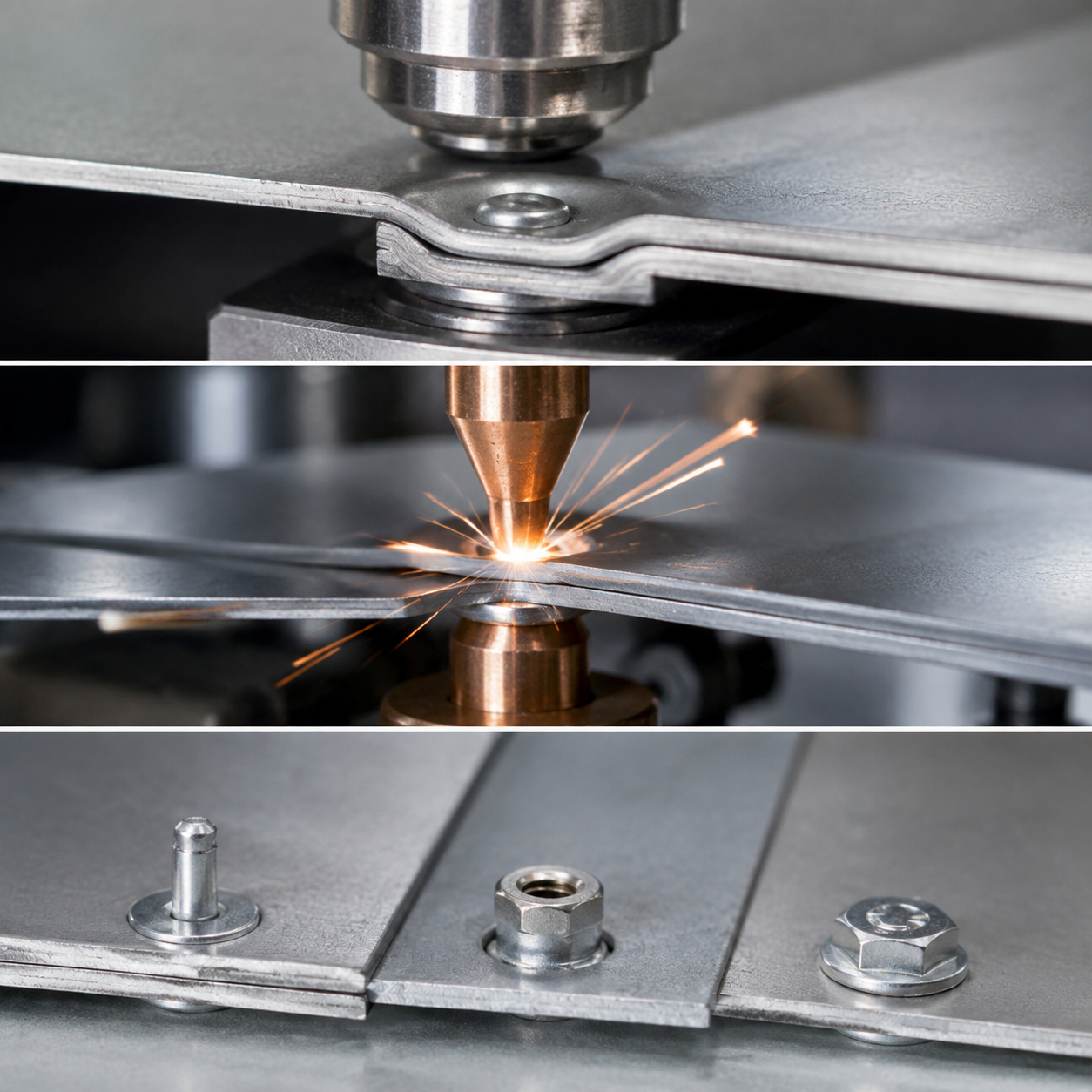
| Decision Factor | Fastener-Free Clinching | Resistance Spot Welding | Other Fastener Routes |
|---|---|---|---|
| Joint Formation | Cold-formed mechanical interlock with a punch and die. | Localized electrical-resistance heat forms the weld nugget. | SPR, blind rivets and clinch nuts add a fastener or insert. |
| Coated Sheet | May preserve more of the coating, but cracking and service exposure still require validation. | Heat affects the coating around the weld and may require process controls or finishing. | Hole, pierce and fastener interactions depend on the selected method. |
| Dissimilar Materials | Can be a candidate when the stack has enough ductility and a workable thickness relationship. | Material electrical and metallurgical compatibility can restrict the joint. | Some fastener systems are designed for mixed stacks, with added consumable and access needs. |
| Visible Surface | Leaves a formed button and a die-side impression. | Can be less prominent after finishing, but heat marks or distortion may matter. | Fastener heads, tails or inserts remain part of the visible geometry. |
| Strength And Duty | Must be tested for the required static, peel, fatigue, vibration and environmental duty. | Must be tested for nugget quality, load path, fatigue and material-specific failure modes. | Fastener pull-out, bearing, fatigue and corrosion interactions may govern. |
| Operating Inputs | No welding current, cooling water or welding electrode dressing for the clinch operation. | Requires electrical welding energy and electrode management. | Requires purchased fasteners and method-specific feed or installation tooling. |
| Best Next Proof | Section geometry plus mechanical and product-functional testing on formed samples. | Weld schedule qualification, nugget inspection and duty-specific testing. | Installed-fastener inspection and duty-specific testing. |
Documented Configurations for HVAC and Appliance Parts
These five examples come from Simitch customer materials and equipment renders. They document different work patterns, but they are not independent performance verification or a promise that the same tooling, cycle or dimensions fit another part.
Evidence Boundary Summary
| Evidence Record | Supplied Data | Buyer Use |
|---|---|---|
| TPC30 Project Record | 0.5 mm to 2.0 mm supplied sheet range; under 8 seconds | Use as a prior configuration boundary, then validate the new formed stack. |
| Damper-Platform Project Record | 2000 mm × 1200 mm × 800 mm supplied footprint; under 8 seconds | Use for quote comparison, not as a guaranteed footprint or cycle. |
| ISO 12996 Test Scope | Each sheet up to 4.5 mm within the published specimen scope | Use as a test-procedure reference, not product certification. |
| Prior-Forming Study | 0.8 mm final strips with 0%, 20%, 47% and 60% prior reduction histories | Use to justify formed-part validation; do not transfer the result to another stack. |
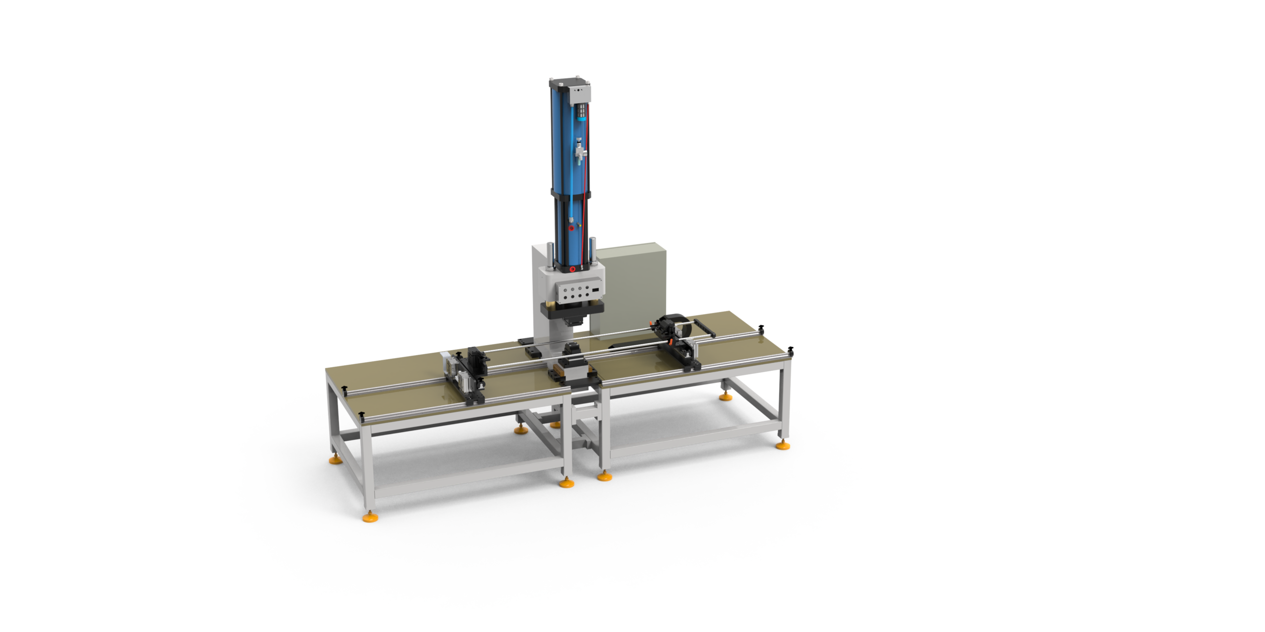
TPC30 HVAC Damper Blade Multi-Point Machine
The supplied configuration uses a Simitch BS30-100-12 pneumohydraulic booster cylinder. Tooling is selected after testing the buyer’s sheet-part stack.
- Material: galvanized or cold-rolled sheet
- Supplied thickness: 0.5 mm to 2.0 mm
- Supplied cycle: under 8 sec
- Controls: foot control, oil-pressure sensor, 5-digit counter
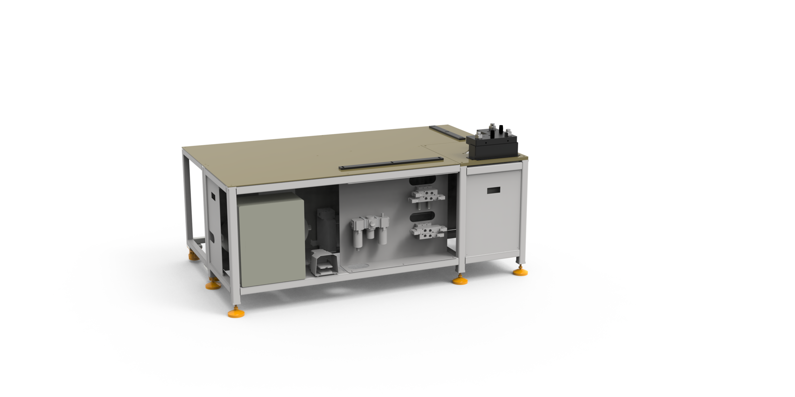
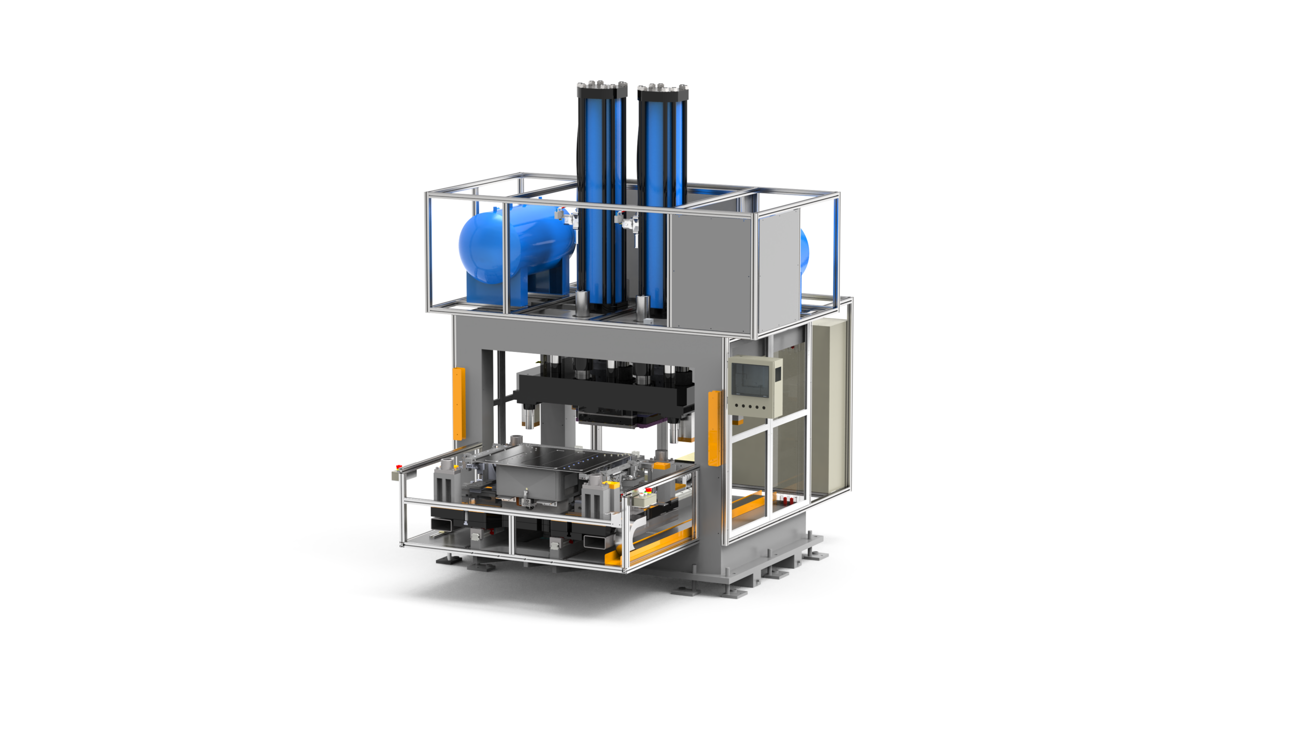
HVAC Damper Corner Four-Point Platform
The supplied platform combines an HZ29-50 working cylinder with an HMPS200-2284 booster. Its four-point die and locating mechanism are designed from the buyer’s product drawings.
- Supplied size: 2000 mm × 1200 mm × 800 mm
- Supplied cycle: under 8 sec
- Frame: integral or welded C-frame steel plate
- Pneumatics: Airtac or quotation-confirmed equivalent
Washing-Machine Front-Panel Four-Corner Machine
The documented machine clinches four product corners in one cycle and supports changeover between several products. Limited reshaping can compensate for defined stamping variation, subject to sample and fixture validation.
- Pattern: 4 corners in 1 cycle
- Drive: Simitch working cylinder plus booster
- Changeover: multiple product variants
- Open proof: stamped-panel tolerance window
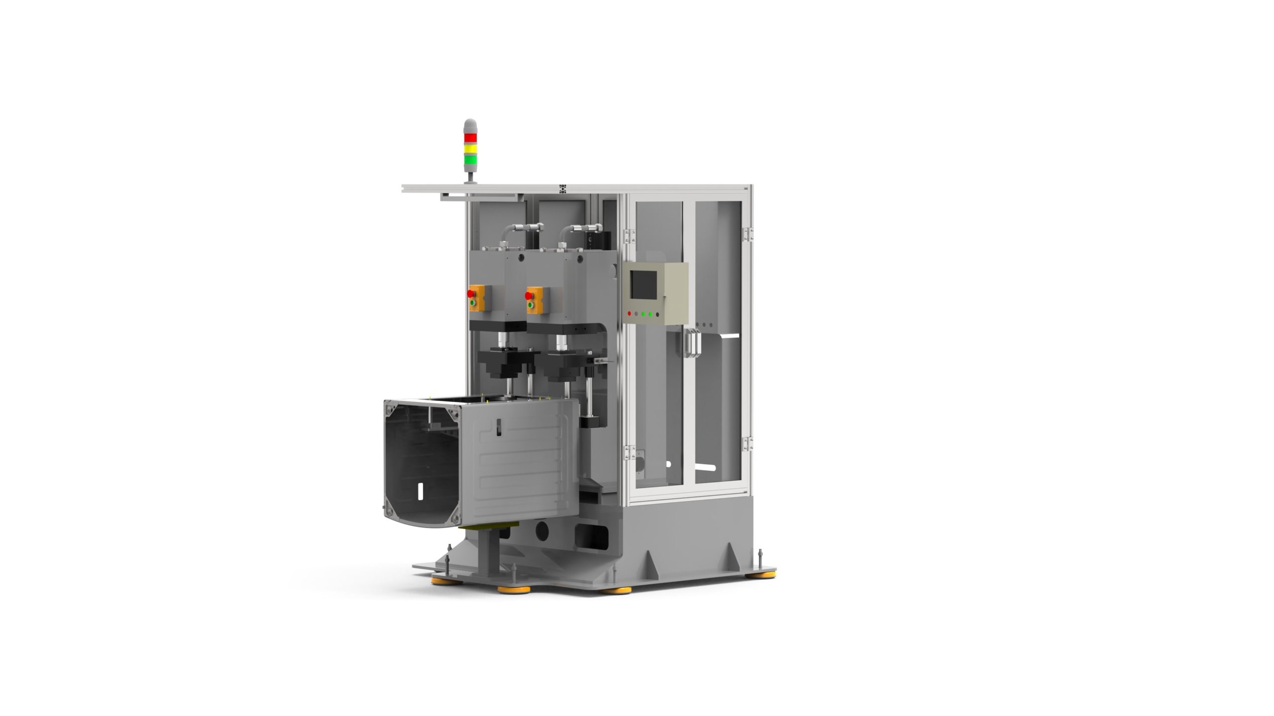
Integrated-Stove Clinching Equipment
The supplied render documents an application example but includes no approved numeric specification. Machine size, force, tooling, cycle, work sequence and availability require drawing review and quotation confirmation.
- Published figures: none approved
- Required next step: part and joint review
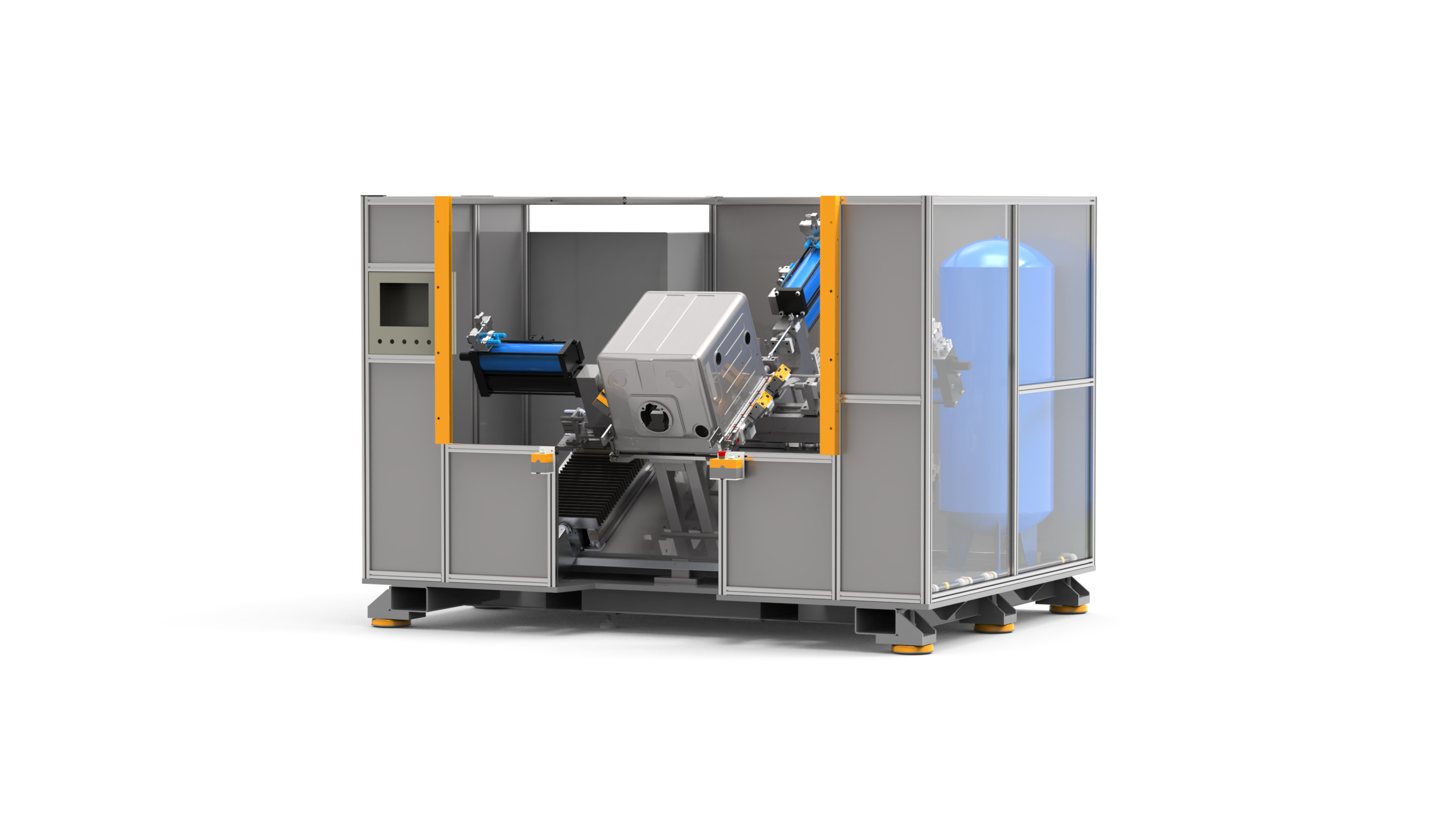
Dishwasher Inner-Tub Automated Clinching Line
The supplied concept has 5 line sections covering manual operations, gluing or welding coordination, automated handling and clinching, conveyor assembly and high-capacity buffering. Its clinching drive uses a Simitch pneumohydraulic booster cylinder supplied with compressed air.
- Handling: robot, gantry and 6-axis robot functions
- Fixtures: 1 robot serving 2 gluing fixtures in the supplied concept
- Buffer: positioning and 2-level buffer conveyor functions
- Open proof: line interfaces, recovery, takt and SAT
Tooling Validation, Quality Controls and Compliance Scope
A drawing review can expose obvious access conflicts, but it cannot close every joint-quality question. Validation should connect the actual formed sample, selected punch and die, measurable joint evidence, product duty and agreed machine-safety scope.
Submit the production stack
Material grade, temper, each layer thickness, coating, forming history and permitted surface marks.
Map every joint
Provide 2D drawings or a 3D model with joint coordinates, datums, edge constraints and cosmetic sides.
Test formed samples
Test parts that represent production bends, stamping variation, layer order and fit-up rather than flat substitutes alone.
Define joint evidence
Agree section geometry, visual limits, force-displacement records and mechanical tests suited to the stack.
Add functional duty
Specify leakage, vibration, peel, fatigue, torque, noise or environmental tests where the final product requires them.
Freeze acceptance scope
Put samples, gauges, records, cycle definition, alarms, guarding checks, FAT and SAT responsibilities into the quotation.
Simitch Application Engineering Principle
“We do not freeze the tooling from nominal thickness alone. We ask for the formed stack, access drawing, part variants and the evidence that must pass before production.”
| Topic | What Simitch can document or supply | What the buyer or integrator must confirm | Commercial record |
|---|---|---|---|
| Joint test basis | Agreed sample plan, tooling, section evidence and available force or test records. | Required load cases, product standard, acceptance limit and statistical plan. | Drawing, sample report and FAT protocol. |
| ISO 12996 reference | A tensile-shear procedure may be referenced within the standard’s published scope. | Whether that procedure covers the actual stack and end-use requirement. | Test-method line in the acceptance document. |
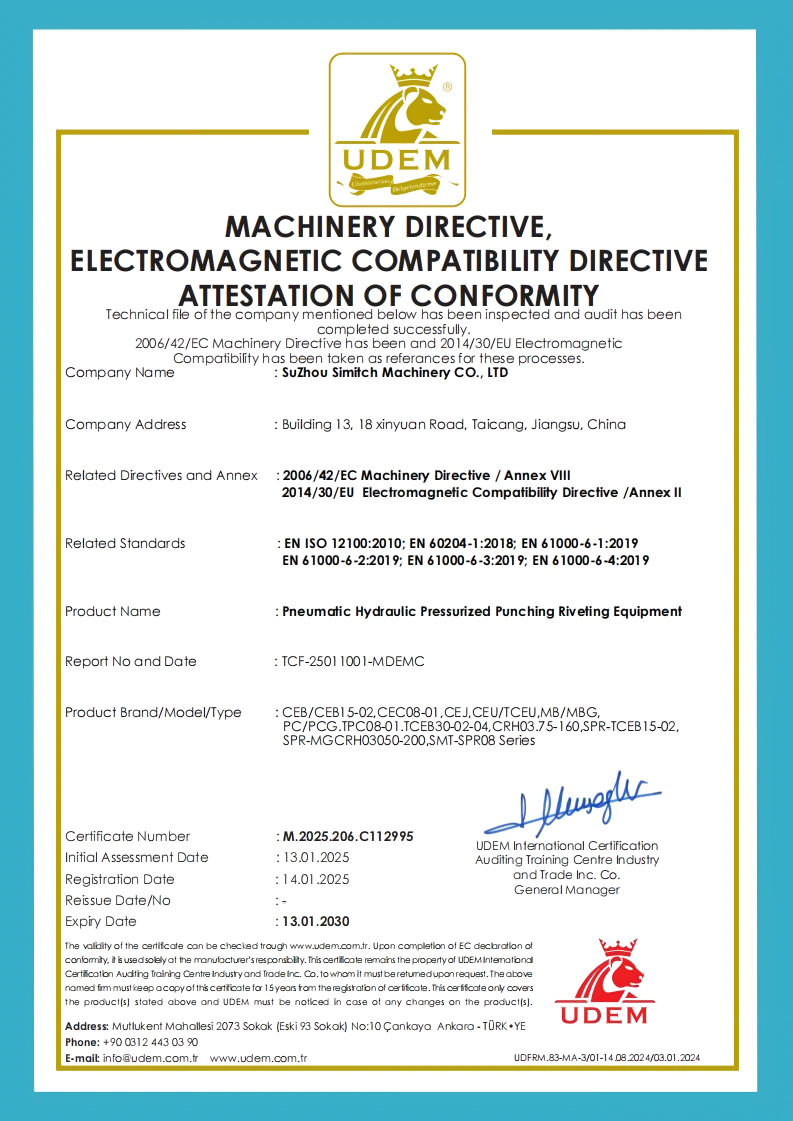
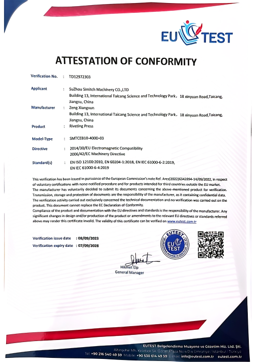
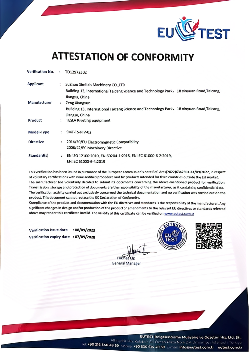
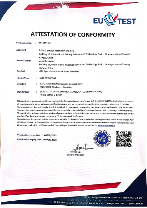
| CE file | Quotation-confirmed machine documents for the supplied equipment scope. | Final line integration, modifications, destination rules and end-product compliance. | Document list and declaration scope. |
| U.S. machine safety | Guarding and safety functions included in the quoted machine scope. | Workplace-specific risk review, point-of-operation protection, lockout/tagout and training. | Responsibility matrix and SAT checklist. |
| ISO 9001 claim | Requested certificate and scope evidence for the manufacturing organization. | Recognition that a quality-management certificate does not certify every joint or end product. | Supplier-document register. |
Classification comes before compliance language
OSHA 1910.217 states exclusions that include hydraulic and pneumatic power presses and riveting machines, while OSHA 1910.212 sets general guarding duties for machines. Equipment classification, point-of-operation hazards and the actual workplace setup must be reviewed before any U.S. compliance statement is made.
Clinching Assembly Evaluation & Comparison Tools
01
Clinching Application Fit & Configuration Selector
Map the part pattern and available evidence to a practical equipment review path. The result narrows the machine architecture; it does not qualify the joint or replace tests on formed samples.
Access Tool →02
Cost per 1,000 Good Joints Calculator
Compare two joining routes with the same cost boundary and accepted-output denominator. Every figure comes from your inputs; the calculator contains no default savings rate, machine price or payback promise.
Access Tool →03
Clinching Quote, FAT & SAT Scope Comparator
Normalize two offers before comparing the headline price. This tool measures scope clarity and included rows; it does not decide which machine can make an accepted joint.
Access Tool →FAQ
A clinching machine uses a punch and die to plastically form overlapping sheet layers into a mechanical interlock. The process adds no separate rivet and uses no welding heat at the joint.
No. Fastener-free clinching forms the sheets themselves, while blind riveting and self-piercing riveting add a rivet, and clinch-nut equipment installs a threaded insert.
Galvanized sheet can be a candidate, but grade, coating, thickness, layer order, forming history and service environment still need sample validation. A coating-safe process claim should not replace section and duty testing.
Start with joint access, part pattern, takt, variants, loading and product-functional acceptance. Select the lowest-complexity concept that holds the validated process window and required work sequence.
Sometimes, but not by default. Compare the actual stack, surface requirement, strength and fatigue duty, coating behavior, access, production inputs and accepted output before choosing either method.
Section geometry, tensile-shear, peel, fatigue and application-functional tests may be relevant. ISO 12996 can provide a tensile-shear test basis within its published scope, while the end product may need additional acceptance criteria.
Tooling, fixtures, handling, controls, guarding, manuals, testing, packaging and site work can change both figures. A drawing and sample review is needed before the quotation can define comparable scope.
Agree the samples, cycle definition, joint and functional criteria, gauges, records, alarms, interlocks, technical files, site prerequisites and responsibility for every open item. Record exclusions as clearly as included work.