Get in touch with Suzhou Simitch Machinery Co., Ltd Company

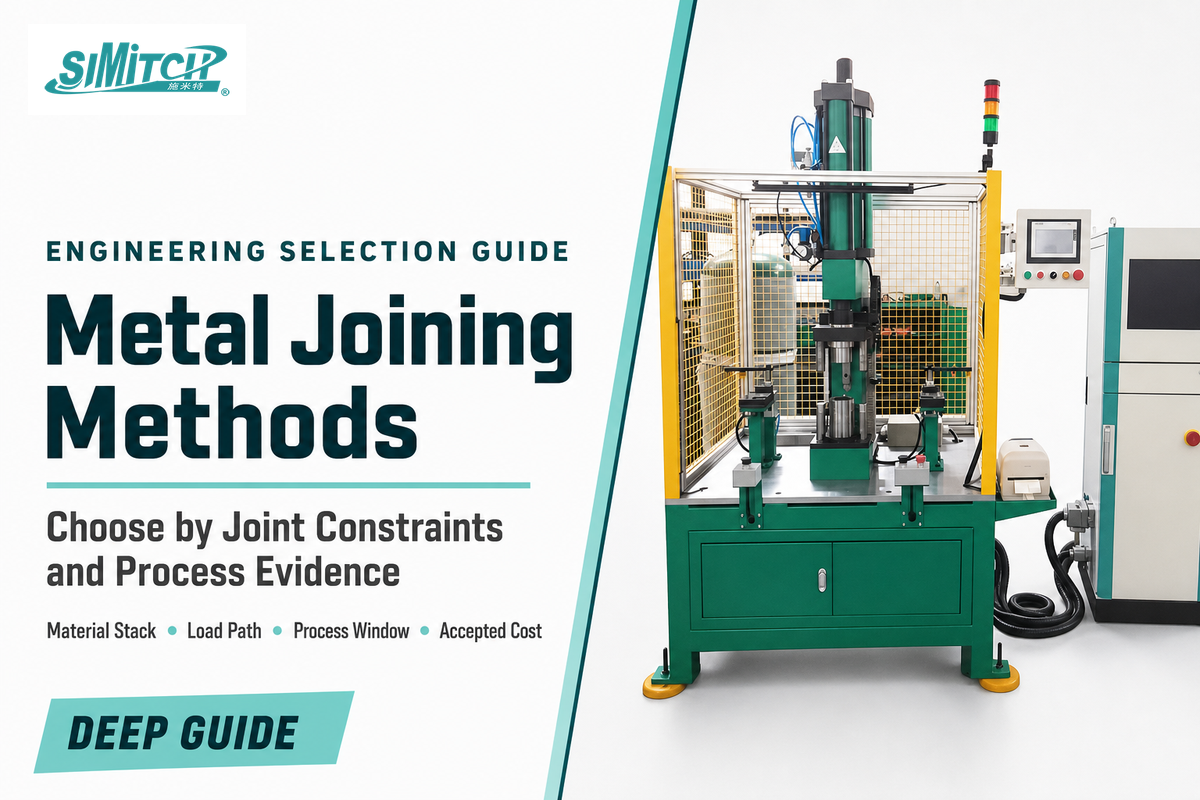
Metal joining methods are production processes that create load-bearing, sealing, electrical, or serviceable connections between metal parts. This guide compares industrial metal joining methods by the material stack, load path, heat tolerance, access, service environment, production conditions, inspection plan, and economic boundary. Define those constraints first, then eliminate process families that cannot meet them.
Updated August 2026 · By XCX
Quick Specs
| Decision sequence | 10 constraints before process selection |
| Main families | Fusion and solid-state welding, brazing/soldering, adhesives, fasteners, cold-forming |
| Release principle | Validate a process window, not one peak result |
| Economic denominator | Cost per accepted joint, with a separate lifecycle boundary |
The best metal joining method is the one that produces an accepted joint across the allowed material, geometry, access, rate, and service window. Nominal strength alone is not a production release criterion.
What Are the Main Families of Metal Joining Methods?
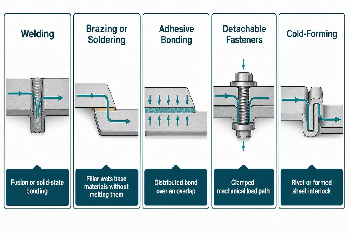
The methods used to join metal fall into five practical families: welding, brazing or soldering, adhesive bonding, detachable mechanical fastening, and permanent cold-forming. NASA’s friction-stir-welding overview also shows why “welding” must distinguish fusion from solid-state mechanisms. Compare how each joint carries load, what it consumes or deforms, and which production constraints it creates during equipment selection.
| Family | Load-transfer mechanism | Production advantage | Primary constraint |
|---|---|---|---|
| Welding | Fusion or solid-state bonding | Continuous or localized permanent joint | Metallurgy, heat, access, safety, inspection |
| Brazing / soldering | Filler wets base materials without melting them | Joins some dissimilar or delicate parts | Clearance, cleanliness, filler, service temperature |
| Adhesive bonding | Distributed bond over an overlap | Low heat and stress distribution | Surface preparation, cure, aging, inspection |
| Detachable fasteners | Clamped mechanical load path | Serviceable and replaceable | Holes, hardware, loosening, added mass |
| Permanent cold-forming | Rivet or formed sheet interlock | No base-metal melting | Ductility, stack order, tooling and access |
A family label doesn’t imply an inherent preference for strength. The joint geometry, directions of loading, fatigue, material choice, and method of assembly and inspection may override a simple “weld vs rivet” heuristic.
Start With 10 Joint Constraints, Not a Favorite Process
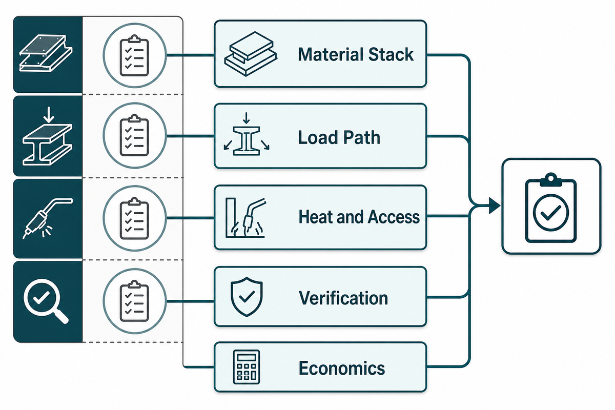
The “10-Constraint Joint Selection Grid” lists only potential candidates. Before calling equipment suppliers for prices, eliminate a process family if it cannot meet a fixed constraint without new materials, geometry changes, additional safety controls, or a different acceptance method.
The grid treats occupational safety and verification as selection inputs: OSHA identifies process-specific welding, cutting, and brazing hazards, while the applicable joint test method must still be chosen for the actual process and stack.
| Constraint | Define before selection | Eliminate or investigate when |
|---|---|---|
| 1. Material stack | Grades, coatings, order, thickness | Cracking, melting, coating damage, or incompatibility is unresolved |
| 2. Load path | Shear, peel, tension, fatigue, sealing | Joint geometry cannot carry the governing load |
| 3. Heat / metallurgy | Distortion and microstructure limits | Thermal input changes properties or dimensions beyond tolerance |
| 4. Access | Flange, edge distance, one- or two-sided tooling | Punch, die, electrode, torch, clamp, or cure fixture cannot reach |
| 5. Repairability | Permanent, removable, replaceable | Service strategy conflicts with an irreversible joint |
| 6. Service environment | Moisture, temperature, chemicals, corrosion | Aging or galvanic controls are undefined |
| 7. Occupational safety | Fumes, radiation, fire, electricity, chemicals | Required controls cannot be engineered or permitted |
| 8. Production | Rate, changeover, labor, utilities | The controlled cycle cannot meet takt or mix |
| 9. Verification | Inspection, sampling, traceability, reaction | Internal joint quality cannot be demonstrated |
| 10. Economics | Accepted-joint and lifecycle boundaries | Quote comparison hides yield or downstream cost |
What is the best way to join two metal objects together?
No process is best in absolute terms. Define the 10 constraints and the governing failure mode, then compare only the families that can meet those inputs. One high peak load on a sample is insufficient when the process cannot reach the assembly, damages coatings, misses takt, or cannot be inspected.
Welding, Brazing, and Soldering Use Heat Differently
Fusion welding melts the base material locally, solid-state welding does not, and brazing or soldering melts a filler without melting the base materials. NASA describes friction stir welding as a solid-state process, which is why “welding” cannot be defined only by base-metal melting. In brazing and soldering, filler metal carries the joint across the prepared interface. Those mechanisms change the heat input, metallurgical risk, surface preparation, equipment, and inspection plan.
| Route | What changes | Useful when | Do not assume |
|---|---|---|---|
| Fusion welding | Base material melts and solidifies | A permanent localized or continuous joint fits the metallurgy | More heat always means more useful strength |
| Solid-state welding | Bond forms below base-material melting | The named process and geometry are feasible | All welding has a fusion zone |
| Brazing | Higher-temperature filler wets the joint | Clearance and capillary flow can be controlled | It is fusion welding |
| Soldering | Lower-temperature filler wets the joint | Loads and service temperature suit the filler system | A low process temperature removes cleaning needs |
A defensible comparison names the exact process. Laser welding, arc welding, electron-beam welding, and friction-stir welding require different access, heat input, real-time controls, and quality evidence. A release plan that says only “welding” leaves those decisions unresolved.
Brazed and soldered joints need a filler that wets clean surfaces within the temperature range allowed by the materials and service duty. The melting point of the filler material is therefore a process input, not a catalog detail. Welding routes also differ: metal inert gas (MIG), electron-beam welding, and ultrasonic welding are distinct choices, so each joining technique needs its own process specification.
A metal joining process label helps organize an initial search, but it does not select a production route. Aerospace applications, for example, use electron-beam and friction-stir processes for different reasons. Alloy, geometry, operating environment, and the quality plan still govern the decision.
Mechanical Fastening, Riveting, Clinching, and Adhesive Bonding
Lower-heat routes can reduce distortion and metallurgical change, but they do not remove process risk. They shift control toward surface preparation, consumables, part geometry, material formability, coating damage, repair strategy, tool access, and the ability to inspect hidden joint features.
- Bolts and screws: removable, but holes, preload, loosening, sealing, and added hardware require control.
- Conventional riveting: permanent and inspectable from the exterior, but often needs prepared holes and access for setting.
- Clinching: forms a sheet interlock without a separate fastener; tool geometry and material formability govern feasibility. Compare clinching machines for cold-forming joints only after the stack is defined.
- Adhesive bonding: distributes load over an overlap and can help isolate materials, but surface contamination, preparation variability, cure, peel, aging, and inspection remain design inputs.
Advantages to test
- Lower thermal input for heat-sensitive sheets.
- Joining options for coated or mixed-material stacks.
- Removable hardware or distributed adhesive load paths.
- Cold-forming routes that avoid a drilled pilot hole.
Limitations to test
- One-sided versus two-sided tool access.
- Surface preparation, cure, or fastener delivery.
- Formability, cracking, coating damage, and corrosion.
- Internal-feature inspection and destructive sampling.
Low heat is not necessarily simple. An adhesive can remove a forming step but adds cleaning and cure control. A fastener avoids cure time but adds holes and consumables. A formed interlock removes the separate fastener but demands suitable access and tighter control of punch-and-die geometry. Compare the complete controlled sequence, not one isolated operation.
These mechanical joining methods can create removable or permanent joints, yet each shifts risk into a different production step. Permanent joining methods such as riveting and clinching demand control of stack order, tooling, access, and acceptance criteria. Compare the complete sequence from part preparation through inspection rather than treating every low-heat route as equivalent.
Engineering note
NASA’s Ti-6Al-4V adhesive-bonding study treats contamination and surface-preparation variability as obstacles to reproducible, durable bonds. It supports preparation control, not a universal ranking of adhesive strength.
Dissimilar Metals Add Corrosion, Coating, and Stack-Order Risks
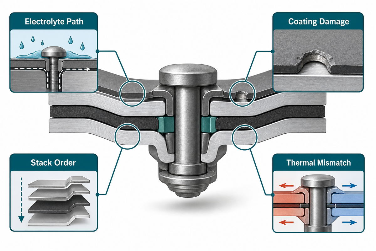
A dissimilar-metal joint requires a corrosion and compatibility plan in addition to a strength calculation. Check electrical contact, electrolyte exposure, potential difference, coating damage, thermal expansion, and brittle reaction products. A peer-reviewed review of mechanical joining for multi-material systems likewise treats material pairing and process selection as coupled decisions rather than a universal recipe.
| Risk | Question | Control to evaluate |
|---|---|---|
| Galvanic cell | Can moisture bridge conductive dissimilar materials? | Pairing, isolation, seal, drainage, coating system |
| Area effect | Could a coating defect create a small anode against a large cathode? | Expose and test realistic defects; avoid universal area ratios |
| Formability | Which sheet must pierce, flare, or flow? | Stack order, local forming trial, cracking criteria |
| Thermal mismatch | Will temperature cycles load the joint or adhesive? | Joint compliance, overlap, service cycling |
Do not state that two metals cannot be joined until the exact alloys, coatings, thicknesses, service environment, and process options are known. A mechanical, adhesive, hybrid, transition-layer, solid-state, or qualified fusion route can remain feasible after a direct-fusion option is rejected.
When Does Self-Piercing Riveting Fit the Joint?
Self-piercing riveting is credible if a semi-tubular rivet pierces through the top layer and flares into the bottom layer without unacceptable cracking or breakthrough. Conventional SPR also requires punch-and-die access, a workable flange, a proven rivet/die combination, and a verification plan. Once the exact alloys, coatings, and process options are known, this screen asks whether SPR can form and verify the actual stack.
| Screen | Condition | Next action |
|---|---|---|
| Fits | Two-sided access, formable stack, usable flange, repeatable orientation | Run a designed stack and tooling trial |
| Investigate | High-strength or low-ductility sheet, coated or dissimilar stack, appearance limit | Compare stack order, rivet, die, support and corrosion controls |
| Reject or redesign | No die access, insufficient flange, unacceptable cracking, sealing demand without a secondary strategy | Change geometry or compare another joining family |
The 2025 AA5052 self-piercing-riveting study offers a useful warning, not a design value: its tested condition with a maximum reported 0.28 mm interlock also had excessive head height. One indicator improved while another failed, so a process window must cover the complete joint-quality set.
Simitch outlines servo, pneumatic-hydraulic, and robotic system paths as well as joint development, verification, and force-displacement monitoring. Use its self-piercing riveting machines page to identify the equipment family, then use the SPR system selector and SPR configuration comparison only when the actual stack and access envelope are specified.
Validate a Process Window, Not Just One Good Sample
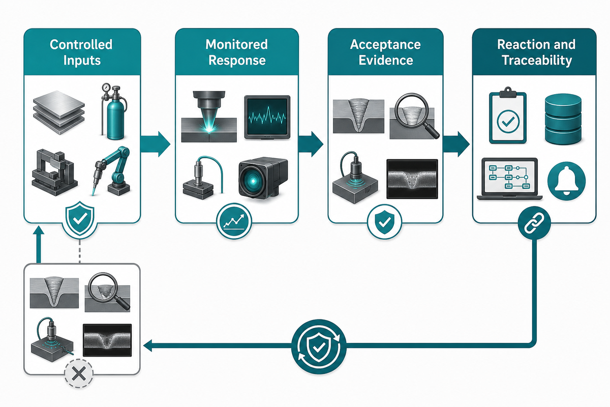
Production approval requires repeatability across defined inputs and controlled responses. The strongest coupon is not necessarily the most producible joint; one result cannot prove material-lot stability, tooling condition, access, delivery, internal geometry, failure mode, inspection, traceability, or recovery from drift.
| Stage | Hidden bottleneck | Release evidence |
|---|---|---|
| 1. Stack definition | Material lot, coating, order, thickness drift | Controlled stack record and tolerance |
| 2. Access / tooling | Flange, alignment, wear, rivet delivery | Tooling trial, maintenance limit, error-proofing |
| 3. Process window | Force, displacement, energy, time, cure, heat | Allowed window and alarm boundary |
| 4. Verification | External appearance hides internal quality | Section, destructive test, dimensional and failure criteria |
| 5. Traceability | A failed trend has no containment path | Serial/lot linkage, sampling, reaction and quarantine rules |
ISO 18278-1:2022 applies to generic weldability procedures for defined resistance-welding processes. ISO 12996:2013 defines specimen geometry and tensile-shear procedure for single mechanical joints on single-layer and multilayer specimens, within a scope of up to 4.5 mm for an individual sheet. Neither provides a universal release sample size or acceptance criterion for every application.
For controlled riveting, compare the required signal and data path with servo riveting assembly systems and the broader riveting system architecture selector. Monitoring is helpful only if limits, ownership, and reaction rules are specified. Those records also feed the Route Pair Case and its Accepted-Joint Cost Stack in the next section.
Compare Cost per Accepted Joint, Not Machine Price Alone
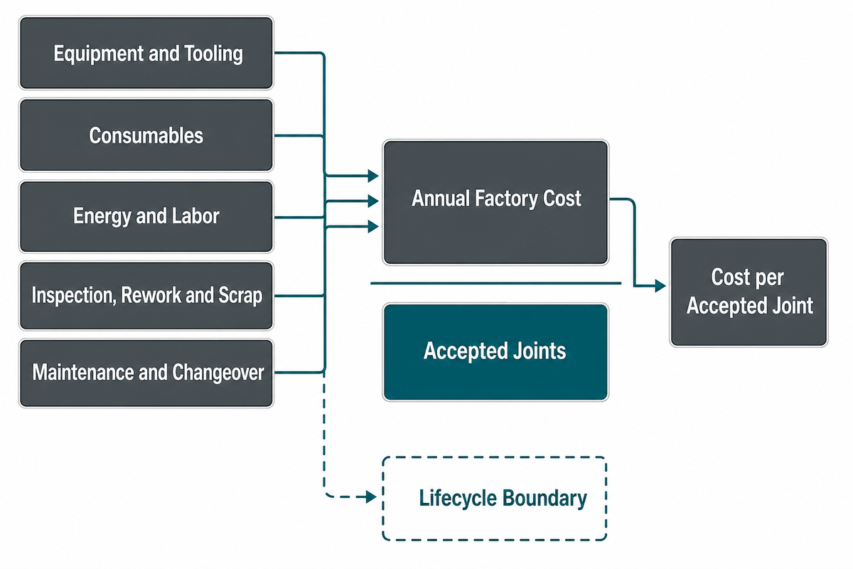
Accepted-Joint Cost divides the annual factory cost of a joining route by joints that pass the agreed acceptance plan. It exposes yield, inspection, rework, maintenance, and changeover that a machine-price comparison hides, but it is not automatically a complete lifecycle-cost result. The monitoring limits, ownership, and reaction rules in the process window supply the yield and inspection inputs that make this denominator credible.
Formula: (annualized equipment and tooling + consumables + energy and labor + inspection, rework, and scrap + maintenance and changeover) ÷ accepted joints.
For mechanical joints, ISO 12996:2013 can define a tensile-shear test procedure within its stated scope, but the factory must still set its own sampling, acceptance, traceability, and reaction rules before “accepted joints” becomes a defensible denominator.
| Illustrative input | Route A | Route B |
|---|---|---|
| Gross joints/year | 1,000,000 | 1,000,000 |
| Accepted yield | 98% | 95% |
| Nominal cycle time | 2,000 ms | 1,800 ms |
| Changeover time | 0.33 hours | 0.58 hours |
| Equipment and tooling | $120,000/year | $80,000/year |
| Consumables | $70,000/year | $20,000/year |
| Energy and labor | $100,000/year | $140,000/year |
| Inspection, rework, and scrap | $60,000/year | $110,000/year |
| Maintenance and changeover | $50,000/year | $40,000/year |
| Annual factory cost | $400,000 | $390,000 |
| Accepted joints | 980,000 | 950,000 |
| Cost per accepted joint | $0.408 | $0.411 |
Decision note: The lowest annual cost is not always the lowest cost per accepted joint. In this hypothetical example, Route B costs less per year but slightly more per accepted joint.
Replace every illustrative input with factory data and run sensitivity ranges. Add service, warranty, field-failure, repair, and end-of-life costs only when those lifecycle boundaries differ materially among routes.
Use the cost per accepted SPR joint calculator as a worksheet, and apply the clinching cost comparison when both cold-forming alternatives remain feasible.
Build a Supplier Brief That Can Be Quoted and Tested
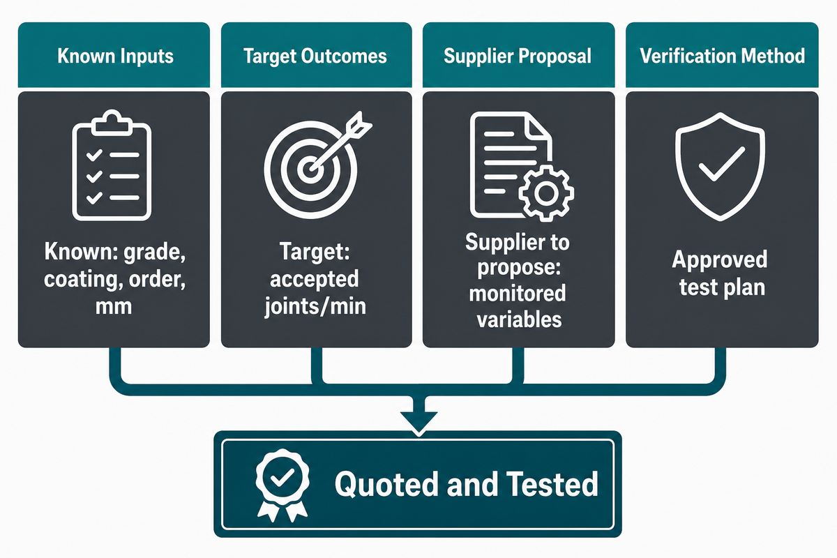
A helpful joining-equipment overview distinguishes identified inputs, desired results, and supplier-recommended options. This prevents an early equipment quote from quietly locking in material, tooling, inspection, or rate assumptions that have not yet been authorized. For automotive resistance welding, the AWS D8 committee scope illustrates why the quote must name the exact process and applicable standard family rather than say only “welding.”
RFQ checklist — copy these into your quote request:
| Parameter | Recommended range | Why it matters | How to verify |
|---|---|---|---|
| Material stack | Known: grade, coating, order, mm | Controls process feasibility | Certificates and sample parts |
| Joint geometry | Known: flange, edge, access, mm | Defines tool reach and support | Drawing and access model |
| Load and failure mode | Target: shear, peel, tension, fatigue | Prevents strength-only selection | Approved test plan |
| Production rate | Target: accepted joints/min | Connects cycle to yield | Timed trial with rejection rules |
| Process window | Supplier to propose: monitored variables | Defines drift detection | Capability trial and alarm test |
| Acceptance | Known: inspection, sampling, limits | Separates a sample from release | Test report and traceability record |
| Utilities / interface | Known: power, air, network | Prevents installation mismatch | Site data and interface document |
| Changeover / maintenance | Target: min, tools, spares | Affects mixed production and cost | Demonstration and maintenance plan |
Simitch was established in September 2006 in Taicang, Jiangsu, and focuses on intelligent joining equipment for automotive components, energy storage batteries, solar photovoltaic products, home appliances, and heating, ventilation, and air-conditioning terminals. That scope is not project evidence. Send the actual sample part and acceptance plan through the riveting request-for-quotation readiness calculator, or request a joint review.
Specify a Verified Joining System, Not Just a Process
A verified equipment specification includes material handling, tooling, monitoring, inspection, traceability, changeover, and reaction rules for the chosen process. Adaptive mechanical joining and data-driven control are active technical developments, but that fact does not prove a sudden shift in buyer demand.
- For multi-material stacks: specify the allowed material history and stack variants, not only nominal grades.
- For automation: define part presentation, error-proofing, tool access, delivery recovery, and safe fallback.
- For monitoring: connect signals to alarms, containment, traceability, and destructive verification; peer-reviewed SPR monitoring research shows why signal interpretation must be bound to real joint quality.
- For standards: name the exact process, edition, test scope, and application-specific acceptance criteria.
DataForSEO showed stable demand for the focus term across 58 available months. That history supports an evergreen decision guide; it does not support a fabricated growth claim.
Frequently Asked Questions
What are the four ways of joining metals together?
A practical four-part answer is welding, brazing or soldering, adhesive bonding, and mechanical joining. For industrial decisions, separate stand-alone fasteners, riveting, and integral interlocks because their tooling, consumables, maintenance, and test requirements differ. NASA’s friction-stir-welding example also shows why a family label may need a mechanism-level distinction.
What is the strongest way to join two pieces of metal?
There is no universal strongest production method. A qualified weld can carry high loads, while heat, coatings, fatigue, distortion, repairability, and service access can favor another route. Define the governing load path and acceptable failure mode, then validate the process window.
What two metals cannot be welded together?
No universal list of unweldable metal pairs is useful for production selection. Direct fusion can fail for a specific pair because of property mismatch or brittle reaction layers, while a solid-state, transition-layer, mechanical, adhesive, or hybrid joint remains feasible. Define exact alloys, thicknesses, coatings, geometry, and service conditions before rejecting a pair.
Is riveting better than welding for sheet metal?
Riveting can be preferable when welding would damage coatings, distort the part, or complicate a dissimilar-material stack. Welding can be preferable when the design needs a continuous joint, a qualified seal, or fewer discrete fasteners. Stack formability, flange access, service conditions, rate, corrosion control, and validation determine the answer.
Can adhesive bonding replace welding?
Adhesive bonding can replace or complement welding when the overlap carries the load and surface preparation, bond-line thickness, open time, fixturing, and cure are controlled. Reject it when peel stress, contamination, service temperature, aging, or bond verification remains unresolved. Require lot traceability and aged-condition testing that represents moisture, temperature, and chemical exposure. A supporting fastener can add handling strength or redundancy, but the two load paths interact, so validate the complete assembly sequence. Record the governing failure mode before release.
What information should I send a joining-equipment supplier?
Send the material stack, drawing, tool-access envelope, target output rate, available utilities, sample parts, and test specification. Mark every field as a known value, a target value, or a supplier-proposed value. Include the acceptance plan and name the owner of each open decision. Attach representative parts from allowed material lots, not only ideal coupons. Ask the supplier to return the proposed process window, monitoring signals, acceptance evidence, changeover plan, maintenance limits, spare-part list, and reaction to a failed joint.
Bring the Joint, Not Just a Machine Wish List
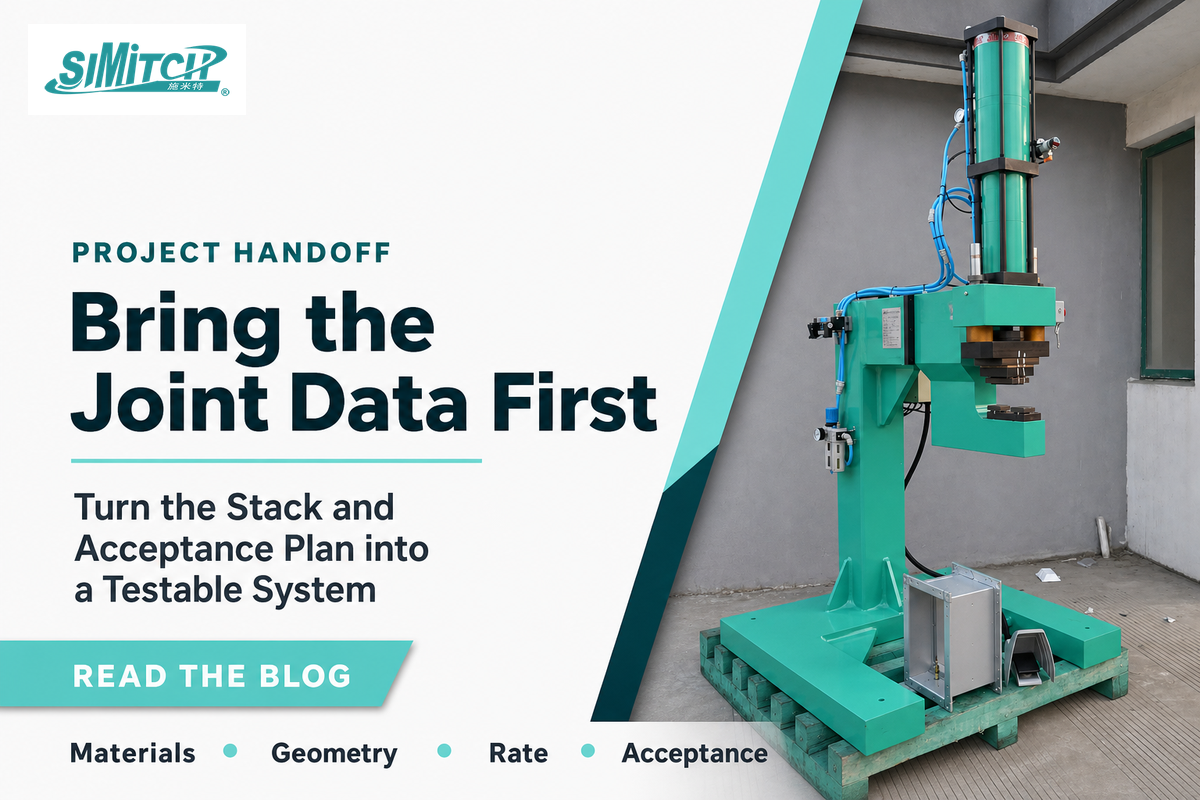
Send Simitch the material stack, drawing, rate, access envelope, and acceptance plan. Where mechanical-joint tensile-shear testing applies, use the scope of ISO 12996:2013 without treating it as a universal acceptance rule. Equipment configuration comes after joint feasibility and verification are defined.
Related Joining Resources
After the joint brief and feasibility review are defined, these resources help compare equipment configurations.
- Riveting equipment overview
- Riveting system comparison explorer
- Clinching equipment path selector
- Servo press systems for battery and electronics assembly
References & Sources
- TWI, common methods of joining metals
- NASA, friction stir welding as a solid-state process
- NASA Technical Reports Server, adhesive surface preparation for Ti-6Al-4V
- OSHA, welding, cutting, and brazing hazards and solutions
- American Galvanizers Association, dissimilar metals in contact
- AMPP, galvanic corrosion basics
- Scientific Reports, 2025, SPR die geometry and joint quality
- Scientific Reports, 2023, SPR defect monitoring
- Mechanics & Industry, 2023, mechanical joining of multi-material systems
- ISO 18278-1:2022, resistance-welding weldability procedures
- ISO 12996:2013, tensile-shear testing of single mechanical joints
- AWS D8 Committee, automotive welding standards family