Get in touch with Suzhou Simitch Machinery Co., Ltd Company

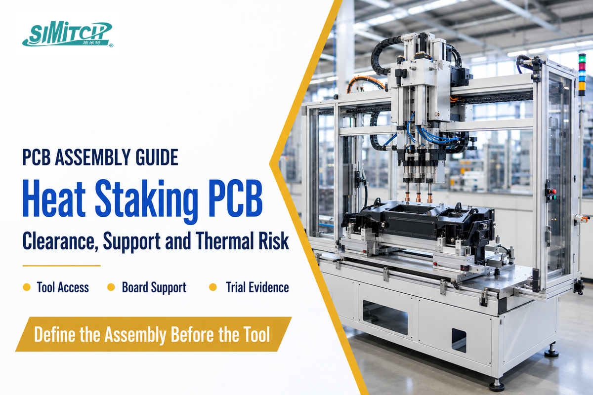
Heat staking PCB assemblies means forming plastic posts into rivet-like heads that hold the board in its housing. The first step is to have a drawing of the complete assembly. The head needs room to form, the tool needs a clear path, and the board needs something to hold it up and support it from below the forming load.
Updated October 2026
Application at a glance
- Formed feature: a thermoplastic boss or retaining lip.
- Retained part: the populated circuit board.
- Joint purpose: permanent mechanical retention.
- Design inputs: resin grade, component layout, tool access and support surfaces.
Heat staking PCB assemblies uses controlled heat to reform a plastic boss into a retaining head. Review the tool path and underside support before freezing the enclosure design. Then test head formation, retention and board function on representative parts.
- A high pull-test result can coexist with a poorly seated head.
- Finished-head clearance and tool clearance are separate spaces.
- Heater temperature differs from the exposure at a nearby component.
- Serviceable products need a planned board-removal route.
Heat staking PCB assemblies: process and joint limits
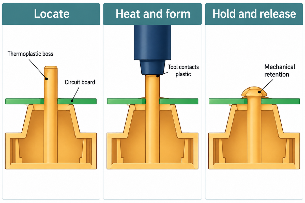
The heat staking process forms a rivet-like head from a plastic post, which is molded into the enclosure. A boss passes through a board hole; softening its exposed end lets the tool spread it over the retained surface. The resulting undercut mechanically locks the board to the plastic body without a separate fastener or other joint consumable.
How does heat staking work?
The staking process locates the parts, heats the exposed thermoplastic, forms the head and releases the assembly once the head holds its shape. Heating and forming can happen in one or two steps. The tool controls material flow. The fixture locates the housing and supports the parts against the applied load.
- Locate. Seat the housing and printed circuit board against their intended datums.
- Heat and form. Soften the exposed pin and move the forming tool through its qualified stroke.
- Hold and release. Allow the head to stabilize, then retract without dragging plastic across the assembly.
In this heat staking application, the boss can retain a dissimilar second component, like a PCB, but it doesn’t fuse the two components together. The process doesn’t melt the board to make the joint. The joint makes no electrical connection and doesn’t seal the enclosure. An adhesive bond, gasket or weld needs to be designed and tested separately.
Set boss geometry and tool clearance together
A 3 mm post, 3.3 mm hole and 2.7 mm exposed length appear together in Branson’s solid-stake design example. These dimensions illustrate the joint geometry. A populated PCB layout requires clearance for the complete punch or heating assembly as it approaches, forms the head and retracts.
Use the Branson PulseStaker guide for a process-specific geometry reference. Its solid, cored and radial forms have different shapes. Radial lip forming bends a raised edge radially inward to retain a part; it shouldn’t be dimensioned as if it were a solid stud.
How much clearance does a PCB heat stake need?
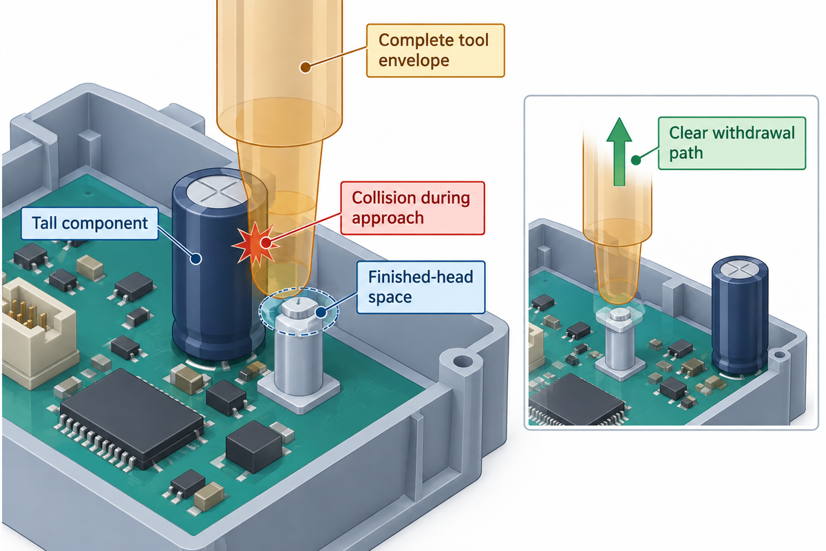
Reserve the forming tool’s full swept volume, including its heater or air nozzle, rather than only the finished head diameter. Add tolerances for the boss, board hole, component position and fixture location; use the actual injection moulding limits for the housing. Define the required accuracy with precise drawing dimensions and a trial. Make any adjustments to address interference along the approach or withdrawal path before machining.
PCB Stake-Space Map
A PCB Stake-Space Map shows the approaching post, finished head, moving tool and nearby components on a single assembly drawing.
| Space or feature | Drawing check | Action when it conflicts |
|---|---|---|
| Incoming post | Boss position against board-hole position | Resolve alignment before forcing the board onto pins |
| Hole | Clearance across the tolerance stack | Revise the fit with the tooling designer |
| Exposed plastic | Volume available above the board | Match post height to the intended head |
| Finished head | Overlap and seating surface | Move copper or components out of contact areas |
| Tool body | Heater, nozzle and punch envelope | Change approach or relocate the stake |
| Retraction path | Tool withdrawal beside tall parts | Remove the collision before machining |
| Underside | Component-free support lands | Shape the nest around the populated board |
| Housing wall | Ribs, ledges and tool access | Revise the enclosure or forming method |
| Service access | Removal path for a failed board | Use a removable mounting design when required |
Joint form guidance: Branson. Drawing actions are an engineering synthesis for the complete assembly.
Example: A tall capacitor stands next to a boss in a diagram. The CAD view shows space between the capacitor and the finished retaining head. As a result, the housing drawing initially seems OK. During a tool review, the heating sleeve occupies that space before the head forms. Reducing the head diameter alone doesn’t fix this. The design team can relocate the boss or capacitor or choose a different access route. Each of these options affects a different drawing. Resolving the overlap at this point avoids ordering a mold around a tool path that can’t reach the joint.
Support the board and housing through the forming load
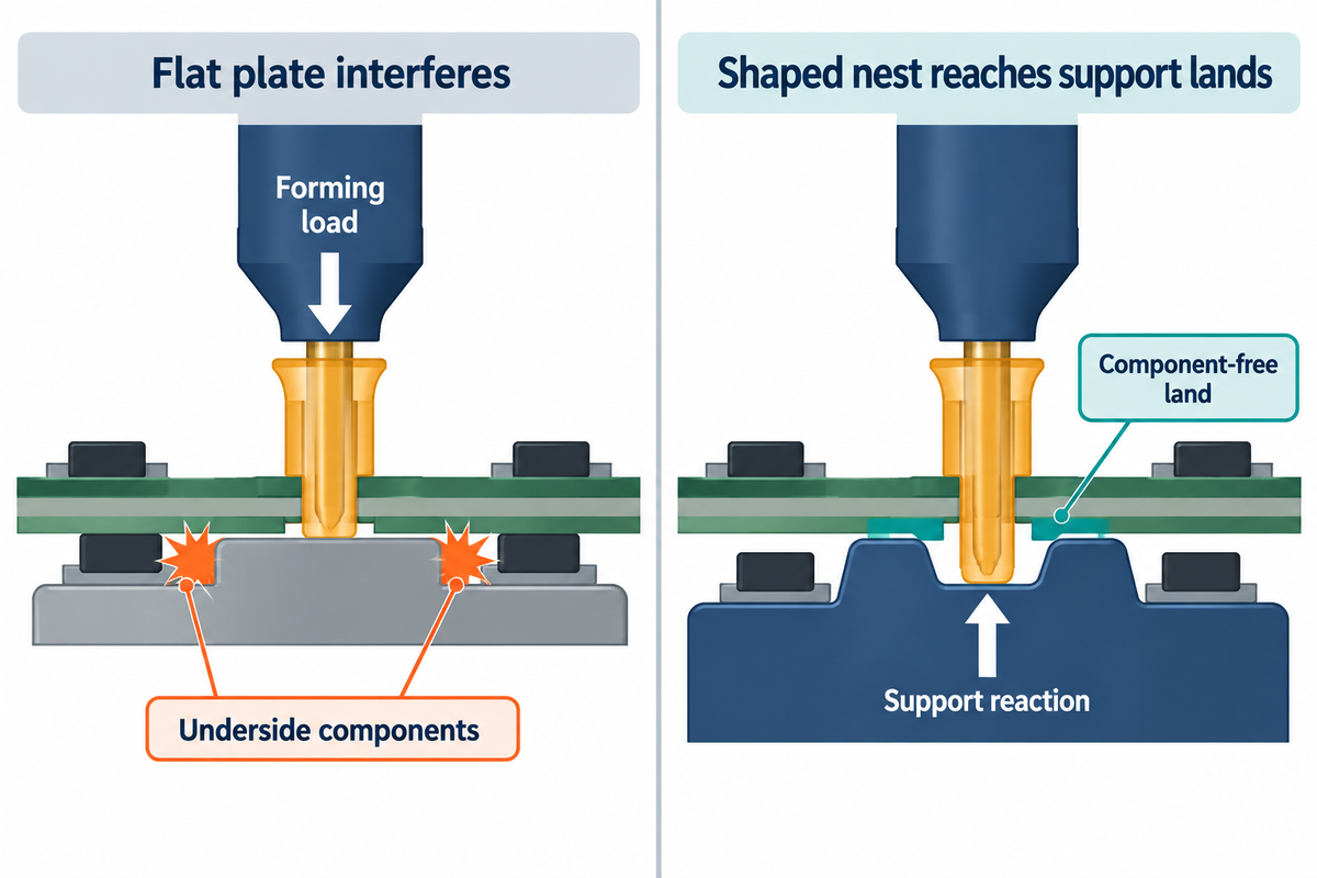
Place support beneath the load path and keep the fixture clear of underside components and solder joints. A board spanning between distant supports can flex as the forming tool presses down. Review the housing seat, board contact and nest together, including tolerances that determine which surface touches first.
IPC/JEDEC-9704 explains strain and strain rate measurements during board assembly, testing, and integration. Too much strain can lead to failures in solder joints, packages and laminate materials. Use the assembly acceptance criteria to determine measurement locations and define measurement limits.
Example: connectors are on top of a control board, with small components underneath. A flat support plate would touch the underside components before reaching the intended support lands on the board. Increasing the clamping force will increase the load through those areas. A shaped nest can reach the designated support areas and locate the housing. If there’s no accessible land near a stake, the engineer has to revisit the housing seat or stake location. A thicker board may change its bending response, but it does not remove contact between the fixture and a component.
A positive seating check is also required for the operator. A trapped cable or an incompletely seated connector can also hold the assembly above its datum, altering the forming position.
Control heat near components and solder joints
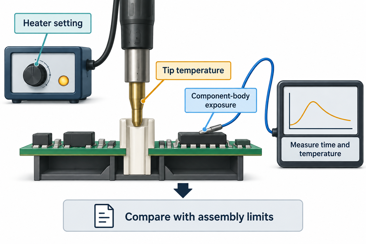
Vulnerable board areas need thermal exposure measurements. Control heat delivered to the plastic boss and measure exposure at vulnerable areas of the board. The heater setting, tip temperature and component-body temperature are three parameters that describe different places. The dwell time and the thermal path determine the amount of heat that reaches a nearby solder joint, connector or electronic package while the post softens.
How hot is too hot for a PCB?
For a populated PCB, the limit is determined by the applicable component, laminate and assembly exposure requirements. Start process development according to the equipment supplier’s material-specific setup for the actual resin grade, then instrument adjacent sensitive parts. Stop a trial when the exposure limits are exceeded or the assembly fails its defined checks.
Material properties need their test definitions. Isola’s DE104 data lists a glass-transition temperature of 135 °C by DSC, a decomposition temperature of 315 °C at 5% weight loss, and T260 of 12 minutes with copper removed. These measurements describe varying responses from laminate. They can’t be used as interchangeable operating temperatures for a populated assembly.
A temperature sensor on a heater can’t indicate the complete thermal history of a neighboring component. During development, record the time and temperature at the vulnerable location and compare to the machine parameter settings. Repeat the comparison after a change to boss size, tip contact, shielding or the loading sequence.
Glass fibre changes the material being formed as well. Dukane’s process guidance describes preheating and controlled forming for filled studs; a blanket rule that filled plastic can’t be staked would discard workable process options.
Match staking technology to the populated assembly
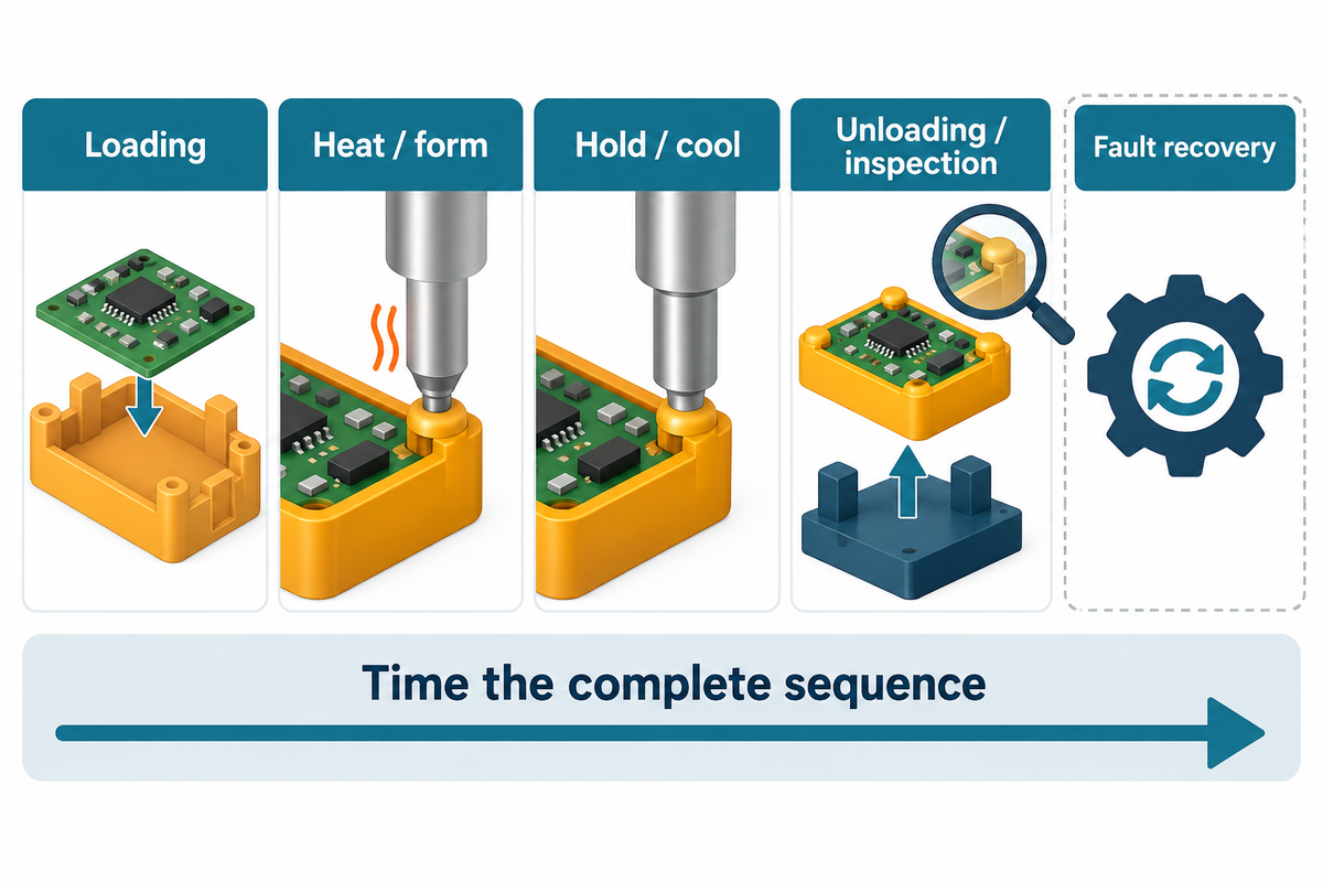
Choose the heating method based on access to the post and the exposure of nearby parts. A continuously heated tip transfers heat through contact with the post. A hot-air staking heater heats the post before the forming tool advances, while an impulse heater heats the post during a controlled cycle. Each method changes the tool envelope, heat path and release behavior.
Cooling is another process-control decision. Dukane describes approaches that reduce the need for active tip post-cooling. Other systems include it in their cycle. The formed head needs enough stability to release without sticking, stringing, or distortion.
Machine handling is another alternative. A rotary table moves parts to different positions without specifying how heat is applied. Multi-point staking equipment can form several bosses together, and a single-point version does it one at a time. Simultaneous tools need space around each mating feature.
For a proposed heat staking machine, map loading → heat/form → hold/cool → unloading/inspection → fault recovery. Time each step on the proposed assembly. A shorter heating step leaves output unchanged if an operator is still waiting for a difficult unload. The joint-to-cell scope builder helps identify tool, fixture and station responsibilities.
Compare heat staking with other PCB mounting methods
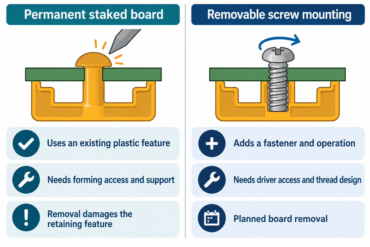
Consider using screws if routine board replacements are required. Think about staking if the enclosure has suitable plastic features and the repair strategy calls for a permanent fit. Snap fits eliminate the use of separate fasteners, but still require space for insertion and latch movement. Consider the complete operation of the assembly, including rejected populated boards and rework.
Permanent staked board
- Forms a head from an existing plastic feature.
- Needs forming access and supported parts.
- Removal damages the retaining feature.
Removable screw mounting
- Adds a fastener and fastening operation.
- Needs driver access and a suitable thread design.
- Allows removal through the intended service route.
Is ultrasonic staking the same as ultrasonic welding?
No. Ultrasonic staking uses vibration to soften and reform a retaining feature; ultrasonic welding joins compatible materials to form a fusion interface. Both processes use tooling to transfer energy, but the joint designs are for different functions. For electronics, assess horn access and vibration transfer as well as retention, and don’t evaluate methods by name.
In an automotive, battery or high-voltage assembly, the board’s mounting decision also must comply with the product’s electrical isolation and service requirements. A mechanically durable joint doesn’t settle those requirements. Use the joining-method screening matrix to assess that comparison prior to tooling the enclosure.
Prepare a representative PCB and housing trial
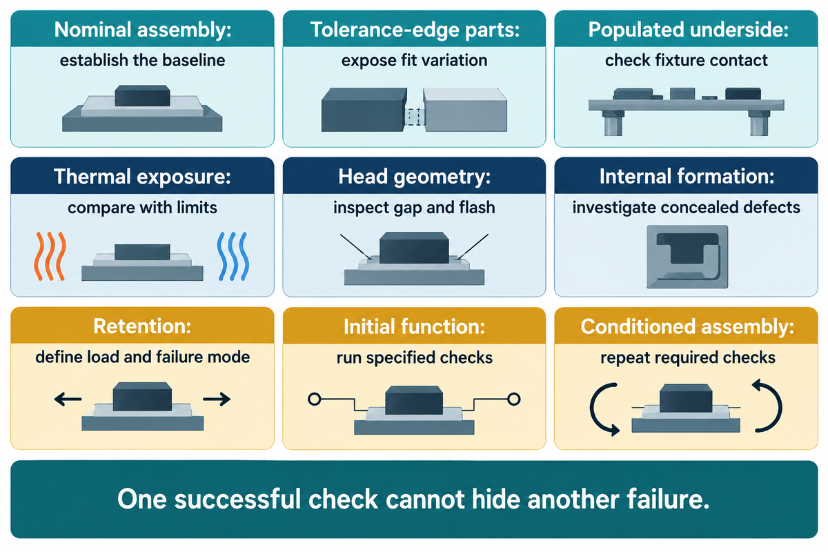
Conduct the test with the intended resin grade, molded housing and representative populated board. Assess formed heads separately from retention and electrical function. Add dimensional and material conditions expected in production and check if formation is repeatable across those conditions. Additional conditioning and/or sectioning checks should be based on the product’s potential failure mechanisms.
A 2026 PA12 study illustrates why several checks matter. Its strongest SLS and turned-pin specimens reached 33.6 MPa and 39.9 MPa at 130 °C and 600 N. Yet the heads left a gap against the FR4 coupon, which the authors rejected for industrial use. Their experiment used unpopulated coupons; the result is a useful warning against selecting a process from pull strength alone.
Internal formation provides an additional check. In a 2020 PP-to-steel hot-air experiment, a fully formed head still contained cold-formed regions and weld lines under shorter heating conditions.
“However, a high percentage of cold forming must take place during the forming process.”
| Trial condition or result | What to inspect or record | Decision it supports |
|---|---|---|
| Nominal assembly | Part identity, resin grade and seating | Establish the baseline setup |
| Tolerance-edge parts | Boss/hole alignment and head contact | Expose a fit that works only at nominal size |
| Populated underside | Fixture contact and board deformation | Revise support before increasing load |
| Thermal exposure | Temperature history at vulnerable locations | Compare with assembly exposure limits |
| Head geometry | Gap, flash, incomplete filling or drag marks | Adjust forming and release conditions |
| Internal formation | Development sections where risk warrants them | Investigate concealed forming defects |
| Retention | Defined load direction and failure mode | Evaluate the mechanical requirement |
| Initial function | Specified electrical and functional checks | Detect immediately observable damage |
| Conditioned assembly | Product-specific conditioning and repeat checks | Assess behavior beyond initial acceptance |
Basis: the cited staking experiments, IPC measurement scope and NASA’s capacitor failure abstract. The acceptance limits are defined by the product requirements.
NASA’s A Tale of Three Capacitor Problems reports latent defects caused by cracked ceramic capacitors. While this instance concerns spacecraft electronics and not staking trials, it explains why initial function and longer-term qualification belong in different rows.
Example: a production team can assemble a board cleanly, and the first powered check passes. The quality engineer finds that the test plan records head photographs but has no defined retention direction or post-conditioning check. The next step is to assign those missing checks before approving the process. The tooling supplier provides development samples and machine settings; the product team provides the acceptance limits and qualification conditions. Purchasing can then price the required sample work instead of comparing an inexpensive visual demonstration with a larger validation package as though the two offers were equivalent.
Scope the tooling quote before comparing prices
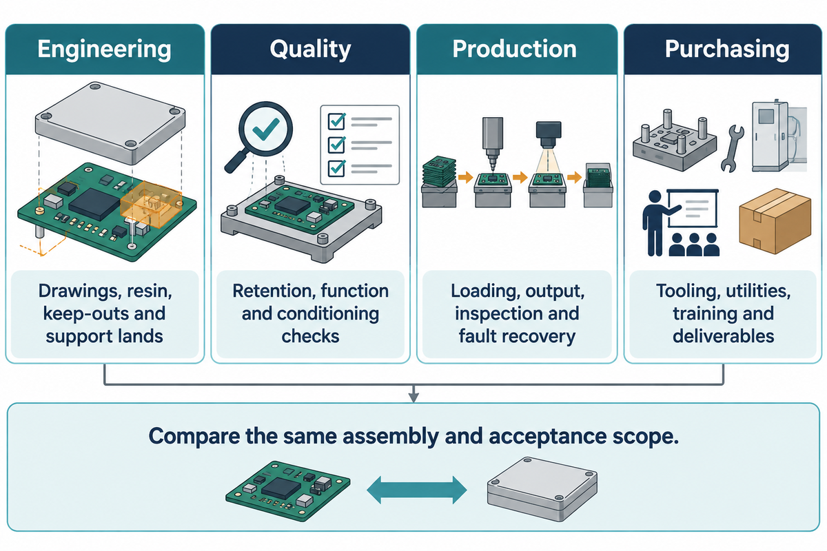
Compare quotes for the same boards, housing, production sequence, and acceptance work. Monitored multi-point stations and a fixture-only price represent different purchases. List the nest, forming heads, heaters, sensing, handling and trial deliverables separately, and show who supplies each item and who approves its result.
NIST’s equipment purchasing guide also includes utilities, ancillary equipment, training and maintenance expectations.
- Engineering: send the board/enclosure drawings, resin grade and component keep-outs. Include underside population and the intended support lands.
- Quality: define retention, electrical checks and any conditioning or sectioning work, including who provides destructive samples.
- Production: describe loading, target output, changeover, inspection and fault recovery. Decide what to automate after timing the full sequence.
- Purchasing: confirm included tooling, utilities, training, spares and acceptance deliverables on the same scope sheet.
SIMITCH’s heat staking machine and custom mold review starts with part files, material, joint geometry and production context. The project readiness scorecard can be used to pinpoint any missing inputs prior to the review. A finance comparison should account for board scrap and rework alongside the fastener and assembly labor being removed from the equation.
Frequently asked questions
Can heat staking damage a PCB?
Yes, through excessive local heat, unsupported force or tool contact.
Evaluate the populated board and housing together, including sensitive components near the stake and support beneath the forming area. A neat retaining head can coexist with mechanical or electrical damage. The acceptance plan should connect approved thermal exposure and loading limits with retention, functional checks and any required conditioning. Those limits belong to the actual assembly and its specifications. Check the tool path and underside contact; damage can begin at either interface before appearing on the head.
What temperature should be used for heat staking a PCB?
Use a resin-specific starting setup and measure the assembly’s exposure.
The process must soften the thermoplastic boss while keeping the board and components within their approved exposure limits. A heater setpoint isn’t the temperature reached at a solder joint or component body. Develop the settings with representative parts, suitable measurements and agreed checks. Resin grade, boss geometry, heating method, dwell and cooling all affect the resulting process window. Record temperature over time at vulnerable locations, then compare that record with the applicable assembly limits before accepting the setup.
Is heat staking better than screws for mounting a PCB?
Staking suits permanent retention; screws provide a planned removal route.
Compare the complete assembly process rather than hardware price alone. Include tooling, loading, cooling, inspection and rejected assemblies. Account for access, available plastic features, retention requirements and the populated board’s value if rework is needed. A production trial should show whether the proposed stake design meets the agreed requirements before the mounting method is selected. If service calls for routine board replacement, price and validate that removal route as part of the mounting decision.
Does a heat-staked PCB joint seal the enclosure?
The retaining head holds the board; sealing is a separate function.
Review the gasket, weld, adhesive or other sealing interface alongside the mounting arrangement. A secure board still needs the enclosure’s specified sealing test. Staking through a board hole doesn’t create a continuous sealed boundary around the product. Test each function.
Can a heat-staked PCB be removed for repair?
Usually removal requires cutting or damaging the formed head.
An acceptable repair needs an approved way to retain the replacement board afterward. If routine replacement is required, compare removable fasteners before committing the housing tooling to permanent stakes. Access for cutting a head also needs room around nearby components.
Is visual inspection enough to accept a heat-staked assembly?
No. Add checks for the assembly’s retention and functional requirements.
Visual inspection finds incomplete heads, flash and obvious damage. Internal formation, retention and latent component faults require different checks. Select those checks around the product’s failure risks and connect production monitoring and sampling to the agreed acceptance criteria for this assembly.
Prepare the assembly for tooling review
Send the PCB and housing drawings with the resin grade, component keep-outs and proposed support surfaces. Add the required retention and functional checks so the trial scope is clear. Discuss the assembly with SIMITCH to define the mold, fixture and equipment work around those inputs.
References & Sources
- Printed Circuit Assembly Strain Gage Test Guideline, Revision A, IPC/JEDEC, 2012.
- Mechanical and structural characterization of heat-staked parts realized by selective laser sintering of polyamide 12, Kuettner, Fischer and Laumer, 2026.
- Development of a Numerical Model of the Hot Air Staking Process Based on Experimental Data, Härtel and colleagues, Chemnitz University of Technology, 2020.
- A Tale of Three Capacitor Problems, Jesse Leitner and Jack Shue, NASA Goddard Space Flight Center, 2016 presentation abstract.
- Manufacturers: Pre-Purchase Guide for Equipment, Celia Paulsen, National Institute of Standards and Technology Manufacturing Extension Partnership, 2020.