Get in touch with Suzhou Simitch Machinery Co., Ltd Company

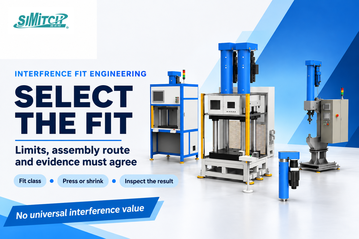
An interference fit describes the case when the shaft or external feature is larger than its mating hole before assembly. Post-assembly, the overlap creates contact pressure and friction. Depending on the tolerance limits, material combination, size, wall geometry, temperature, surface condition, load and process capability, the friction might be appropriate or excessive. Use the worksheet and evidence path to get an initial idea, and then release the joint for project-specific analyses and tests.
The four decisions to make
- Classify the fit as clearance, transition or interference.
- Calculate minimum and maximum interference from actual limits.
- Choose pressing, heating or cooling for the assembly route.
- Verify dimensions, temperature, force evidence and acceptance ownership.
What Is an Interference Fit?
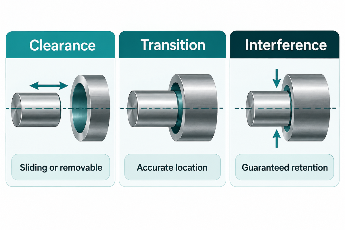
An interference fit joins parts when the shaft is larger than the bore before assembly. The resulting contact pressure can resist movement, but the fit class does not set a universal value. The resulting contact pressure can resist movement, but the fit class does not set a universal value. The complete joint review still needs the tolerance stack, material stiffness, wall geometry, surface condition and temperature.
How do interference fits work?
An interference fit works by creating an overlap before assembly; the shaft pushes against the bore and the elastic response creates contact pressure after seating. Friction at that interface resists relative movement, while the actual result depends on the complete tolerance stack, material stiffness, wall geometry, surface condition and temperature. The fit class describes the relationship; it doesn’t replace a joint calculation or acceptance plan.
| Fit family | Guaranteed pre-assembly condition | Typical decision question |
|---|---|---|
| Clearance | The hole remains larger than the shaft across the limits. | Must the parts slide, rotate or be removable? |
| Transition | The tolerance zones can produce either a small gap or a small overlap. | Is accurate location more important than guaranteed retention? |
| Interference | The shaft remains larger than the hole across the limits. | Can the parts, tooling and surrounding structure tolerate the assembly route? |
NSK uses the following three classifications to define the relationship between a bearing shaft and its housing. These classifications describe the state prior to assembly and don’t provide a definition for universal contact pressure, assembly force or safe interference value. NSK’s fit guidance also states that insufficient interference can lead to fretting and creep, while excessive interference can reduce the life of the bearing and increase the stresses in the system.
Types of Interference Fits and Fit Classes
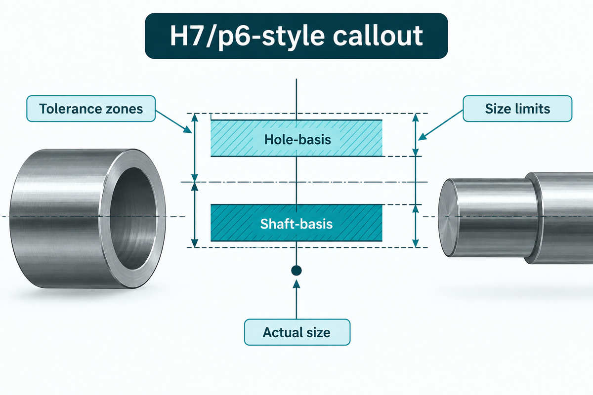
Although fit notation provides a shorthand language to define joints, it is by no means a substitute for a full joint analysis. ISO 286-1 defines the code system and terminology for tolerances on linear sizes; ISO 286-2 provides deviations for commonly used hole and shaft classes. Both 2010 editions were reviewed and confirmed in 2026; confirmation keeps the edition current and does not create a new set of fit values. Confirm the edition and range prior to using a table in a production drawing.
What an H7/p6-style callout does
- It identifies tolerance zones and the hole-basis or shaft-basis convention used for tolerance grades.
- It lets the team calculate the smallest and largest possible fit for a defined nominal size by applying tolerancing from the basic size.
- It doesn’t establish the part’s wall stress, operating temperature, surface texture, friction, tool alignment or acceptance rule.
Consult the fit type associated with the function of the two mating parts. A shaft and a hole intended for free movement are reviewed differently from a joint intended for a fixed position. In a loose fit, some clearance may be allowed. Excessive clearance may be unacceptable for correct location.
Tolerances are determined with respect to a baseline size. Actual size, along with that baseline and the size limits, determines whether clearance or interference exists. In an ISO callout, the tolerance determines the width of the permitted band, and the letter relates the band to the baseline.
Different types of fits include locational clearance for a part that must locate while being separable, and locational interference fit where positive retention is intended. A drive fit callout requires the governing convention. Interpret a medium drive description against its nominal size band. A force fit callout doesn’t define a limit for allowable stress. Categories of interference help express intent, while limits defined on the drawing determine the actual condition.
The ASME B4.1 public description covers preferred limits and fits for non-threaded cylindrical parts. If your team works from ANSI B4.1 conventions or Machinery’s Handbook, retain the cited edition and units with the calculation. A name for the degree of tightness cannot take the place of the limits innumerical forms of features that are to be manufactured.
In mechanical engineering, a clearance fit and an interference joint solve different functional problems. When verifying shafts and holes, keep clearance and interference results adjacent to their limiting dimensions. A calculator can check the arithmetic; it can’t choose the governing design requirement. A fit can provide a joint through frictional contact pressure. It might need no additional fasteners, but some designs add fasteners or adhesives for a different function in the joint. Keep retention mechanisms obvious. Designing for a secure joint is a governing design requirement, but evidence for the actual load case is needed to verify that secure connection.
What are the three types of tolerance fits?
There are three broad families: clearance, transition and interference. The most important engineering distinction is the assurance across the tolerance range. A transition fit can yield the desired result for an individual pair. An interference fit assures the range of interest, but the safe amount still depends on the materials and the service.
How Much Interference Should You Use?
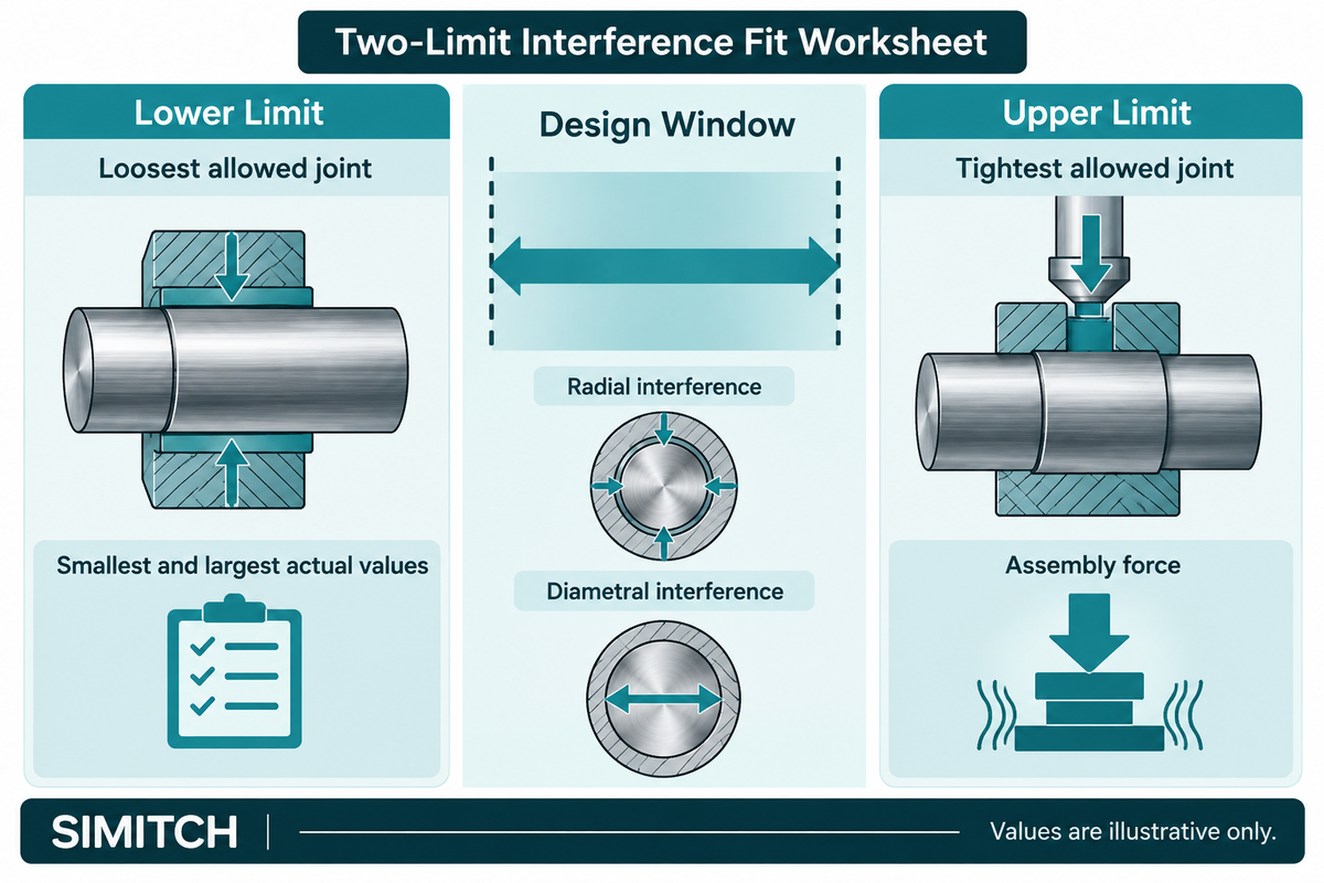
There’s no universal interference amount that’s safe for every shaft, hub, bearing or bushing. For a starting point, use the smallest and largest actual values on the drawing, then check retention at the low extreme and consider clearance, assembly force and risk of failure at the high extreme. When expansion occurs, the answer can change substantially.
Two-Limit Interference Fit Worksheet
Two-Limit Interference Fit Worksheet. Use this worksheet to separate two decisions: will the loosest allowed joint retain the load, and will the tightest allowed joint survive assembly and service? Keep the geometry, operating condition and evidence plan beside those two cases. It’s a design aid, not a universal tolerance table.
| Field | Record | Why it changes the decision |
|---|---|---|
| Shaft and bore limits | Minimum/maximum finished diameters | Defines minimum and maximum diametral interference. |
| Engagement and diameter | Nominal diameter and contact length | Changes contact area, pressure distribution and force. |
| Material and geometry | Modulus, Poisson ratio, strength, wall ratio | Controls elastic expansion, contraction and stress. |
| Operating conditions | Temperature, torque, axial load, vibration | A room-temperature fit can change in service. |
| Process evidence | Method, lubrication, alignment, force trace and acceptance rule | Separates a design fit from a repeatable production process. |
For a straight cylindrical pair, define diametral interference as δ = shaft diameter − bore diameter. Calculate δmin from the smallest shaft and largest bore, and δmax from the largest shaft and smallest bore. GGB uses dimensional extremes for sleeve-bearing press-fit design. Its next step is an application-specific contact-pressure model; then it estimates installation force with F = p × A × μ. Those relationships are useful screening tools, not universal acceptance limits.
For concentric, elastic, thick-walled members, Lamé compatibility relates pressure to interference, radii, Young’s modulus and Poisson ratio. A 2016 analytical study relates pressure to interference within those assumptions; its case-study numbers aren’t recommended production limits. Short hubs, interrupted or tapered fits, plasticity, edge effects, non-axisymmetric features and temperature can require a corrected model, finite-element analysis or physical correlation.
Worked tolerance example: calculate the two limits
Suppose a drawing permits a shaft from 20.020 to 20.035 mm and a bore from 20.000 to 20.010 mm. These are invented dimensions for arithmetic only, not recommended fit values for any material or load.
| Case | Calculation | Decision still needed |
|---|---|---|
| Minimum interference | 20.020 − 20.010 = 0.010 mm | Will the lowest overlap retain the required load in service? |
| Maximum interference | 20.035 − 20.000 = 0.035 mm | Can the tightest pair survive the stress and installation force? |
Both results are positive, so this dimensional example stays within the interference family. That answers the fit-class question. It doesn’t answer the pressure, torque, bearing-clearance or press-capacity question: those calculations need the actual material properties, engagement length, wall geometry, surface state, friction assumptions and temperature range, followed by a validation plan appropriate to the joint.
Keep radial and diametral interference distinct. For the same concentric pair, the radial overlap is half the diameter difference; passing a diametral value into a model that expects a radial value doubles the intended input. High accuracy begins with the right definition. A high precision measurement can’t rescue a calculation that uses the wrong variable.
Why do diameter, wall thickness and material pair change the result?
The same overlap can create different pressure when the surrounding wall or material stiffness changes. SKF’s bearing guidance treats thin housings and hollow shafts separately because they deform differently. Use actual geometry and properties, then check local stress and operating clearance. Don’t turn a catalog fit class into a blanket rule for every bushing, hub or rotating shaft.
Press Fit vs Shrink Fit Assembly
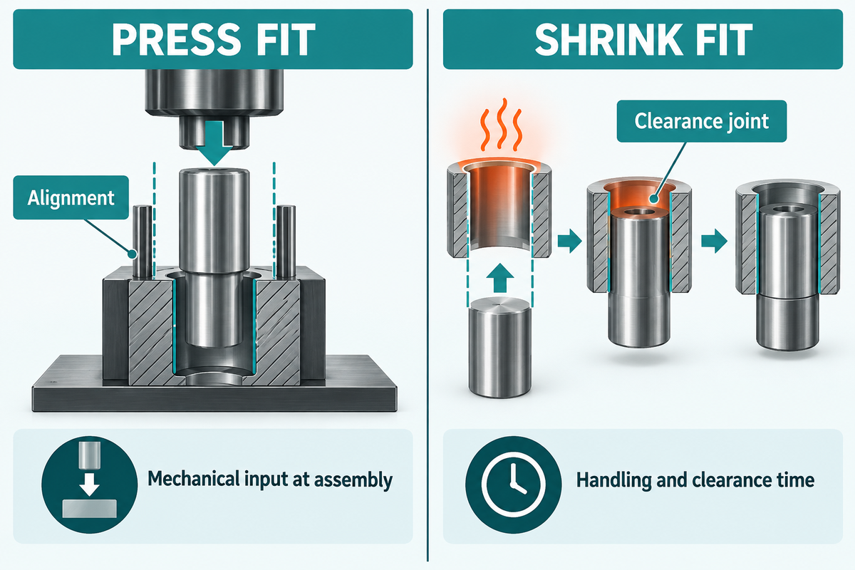
Both the press and shrink methods create the same interference joint through different pathways. The press fit provides mechanical input at assembly. A shrink fit creates a clearance joint by heating the receiving part or cooling the insert, then restores interference as the parts come to the same temperature.
| Route | Choose it when | Main evidence and risk |
|---|---|---|
| Press fit | The force is manageable and the parts can be aligned and supported. | Record force, stroke, alignment and which ring or feature receives load. Wrong tooling can damage parts. |
| Heated shrink fit | Interference or size makes room-temperature pressing excessive or damaging. | Control temperature, gradients, dwell, seals and material limits; manufacturer instructions govern. |
| Cooled shaft | The outer part must not be heated or the shaft can be handled safely under a controlled cooling route. | Control moisture, handling, clearance time and final temperature equalization. |
NSK mounting guidance recommends loading the correct ring with suitable tooling and warns against misalignment, open flames and direct impact. It also describes shrink fitting for large bearings where press force would be substantial. These are manufacturer instructions for stated bearing applications, not a universal temperature or force limit for arbitrary parts.
A chamfer or other designed lead-in can help guide insertion, but it can’t correct a fixture that supports the parts on different axes. Compare the assembly technique using the amount of force the part can tolerate as well as the forces required by the process. The same nominal overlap can behave differently if the lubricant, surface state or alignment changes between trials.
A study comparing interface pressures found uneven contact in its shrink-fit specimens and scuffing in severe press-fit cases. These results describe the tested joints, rather than ranking one assembly route as universally better; they reinforce the need to qualify the actual interface, tooling and surface condition.
Is a press fit the same as a shrink fit?
Press fit and shrink fit create the same kind of retained joint, but they assemble it differently. Pressing forces the parts together at the current temperature. Shrink fitting changes a dimension temporarily with heat or cooling so the parts can be positioned with less mechanical force. The route should be chosen from the actual fit, materials, access, damage risk and process controls.
Materials, Surface Finish and Temperature
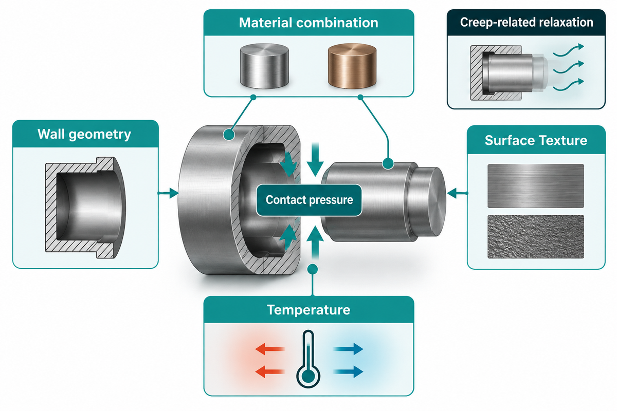
Material names alone don’t define fit behavior. Record modulus, Poisson ratio, strength, thermal expansion, heat treatment, coatings and wall geometry. SKF says shafts or housings made from materials other than steel or cast iron may need different fits because strength and thermal properties differ. It also treats hollow shafts and thin housings separately.
Surface
Texture can smooth during assembly and reduce effective interference. Control size, roundness, cylindricity and texture together.
Temperature
Measure at a controlled reference condition and check transient and steady-state operating temperatures for dissimilar materials.
Uncertainty
Define the measurand and include calibration, repeatability, temperature, form and correlation effects.
The NIST overview cites the GUM and VIM definitions of measurement uncertainty. These definitions describe uncertainty in the values attributed to a measurand. They don’t prescribe an interference-fit tolerance or acceptance rule. Define that rule separately from the uncertainty estimate, using the governing drawing and buyer requirements.
Also separate assembly-day retention from long-term retention. Research on high-temperature interference joints treats creep-related relaxation as a cause of contact-pressure decay over time. That’s a specific service regime, not a prediction that every room-temperature metal fit will loosen; include time-dependent material behavior when the duty makes it relevant.
Can surface finish change an interference fit?
Yes. Mating peaks can smooth, and the resulting contact can differ from the apparent pre-assembly diameters. SKF notes that smoothing can reduce interference. Treat surface finish as one input in the tolerance and process review rather than applying a generic correction factor without a source.
Inspection and Force-Displacement Monitoring
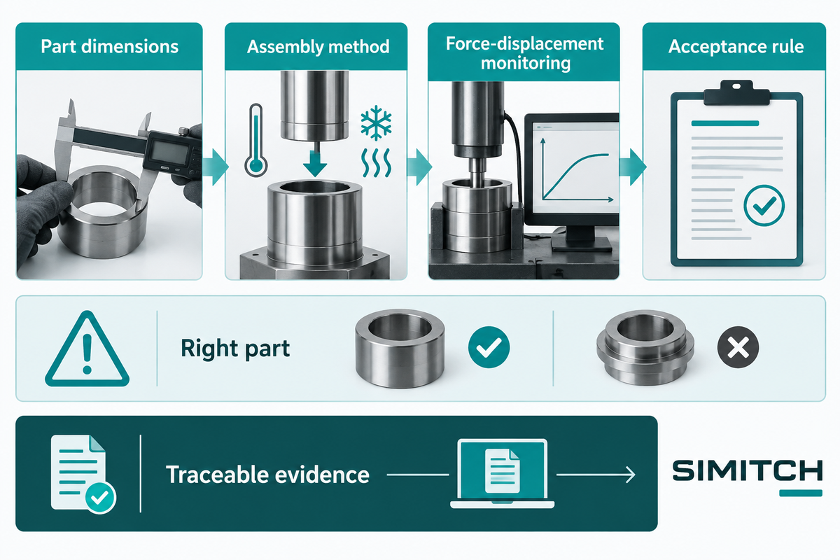
ASSEMBLY describes force and distance sensing as a way to detect changes during pressing. The evidence matrix below is an engineering review aid, rather than a published acceptance standard. Inspect the joint as a linked record. Capture the actual shaft and bore measurements, temperature, form and runout, surface condition, part IDs, tooling and recipe revision, assembly route, force-displacement trace, and final disposition. A force trace can screen a validated process window, but it can’t replace evidence that the measured part was the right part or that the project acceptance rule was satisfied.
| Machine signal | Part evidence | Release decision |
|---|---|---|
| Within a validated window | Dimensions, geometry and temperature meet the project rule | Continue the defined sampling and trace-retention plan. |
| Within a validated window | Damage, wrong dimensions or wrong sample identity | Contain and challenge the monitoring validation. |
| Outside the window | Sample appears acceptable | Hold release until the deviation and reference identity are explained. |
SIMITCH publicly describes servo press systems, press-fitting configurations and force-displacement monitoring on its current equipment site. That statement supports a supplier conversation about process monitoring; it doesn’t establish a particular press model’s accuracy, repeatability or ability to meet a joint’s tolerance. Ask for a configuration-specific feasibility trial, tooling definition, trace format, calibration status and FAT/SAT acceptance criteria.
What should a press-fit acceptance record contain?
At minimum, link the actual part dimensions and temperature to the part ID, tool and recipe revision, assembly method, force trace, operator or cycle identity, inspection result and disposition. Keep the project limit visible. A green curve without that context is a screening observation, not a complete acceptance record.
Applications, Failure Modes and Limits
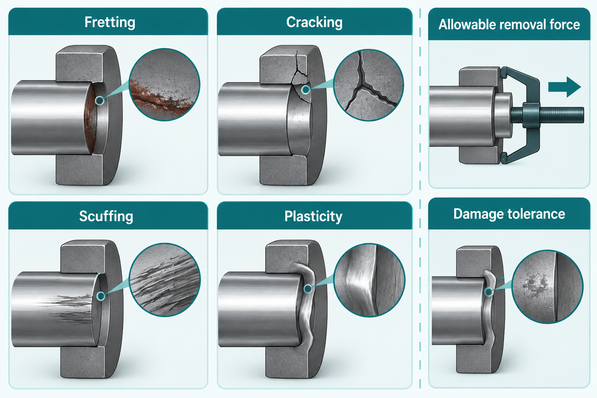
Interference fits occur on bearing seats, bushings, dowel pins, gears, hubs and other cylindrical joints. The retention objective and failure risk are different in these examples. A bearing ring may need Ra to control creep under a rotating load, while a serviceable bushing may require a removal plan. A controlled pin-and-hole drawing is still necessary for a dowel or locating pin; the product name alone doesn’t dictate the hole tolerance.
| Application | Dominant review question | Evidence to retain |
|---|---|---|
| Bearing seat | Will the ring creep, and will fit-induced clearance loss or heat damage the bearing? | Bearing limits, seat limits, load direction, temperature and operating clearance. |
| Bushing or sleeve | Is retention balanced against installation force and future removal? | Material, wall ratio, lubrication, press-force window and removal method. |
| Dowel or locating pin | Is accurate location required, and what will happen during service or repair? | Pin standard, hole process, alignment, retention objective and service plan. |
| Gear, hub or coupling | Does the joint transmit the load without overstressing the hub or shaft? | Torque/axial load, contact length, wall geometry, pressure model and validation. |
| Motor rotor or impeller | Will speed, balance and temperature change the fit or create fatigue risk? | Operating envelope, balance, thermal mismatch and overspeed review. |
| Pulley or flywheel | Does the joint carry torque without slip during start, stop and shock? | Torque history, key or keyless design, contact length and retention test. |
| Seal or sleeve housing | Will the fit retain the part without damaging the sealing surface? | Surface finish, concentricity, lubrication and leakage acceptance evidence. |
| Precision locator | Is location repeatable while removal remains possible? | Location tolerance, service tool, replacement plan and measurement uncertainty. |
NSK describes two different failure directions: a loosening fit can permit creep and fretting, while excessive interference can crack a bearing inner ring or reduce its internal clearance. These bearing-specific mechanisms explain why both tolerance extremes matter. Research on disassembly also uses specific materials and geometry; a study summarized by engineering academic Hany Hassanin doesn’t establish a universal removal-force reduction for other joints.
For cyclic loading, the average pressure is only part of the design consideration. Pedersen studied shaft-hub contact-pressure distribution and the fretting-fatigue risk at stress concentrations. Consider local geometry and the load cycle for the review, instead of using a total holding-force estimate to predict fatigue-life.
Can every interference fit be disassembled?
No; consider the fit class, material, access, allowable removal force, damage tolerance, and whether other surrounding components can be supported. Consider the removal path and the condition of the component to be replaced during a design review before releasing a joint that requires maintenance. This is the disassembly decision, and it should be visible with the locational decision and the ANSI or ISO convention used for the drawing.
Interference Fit RFQ and Design Review Checklist
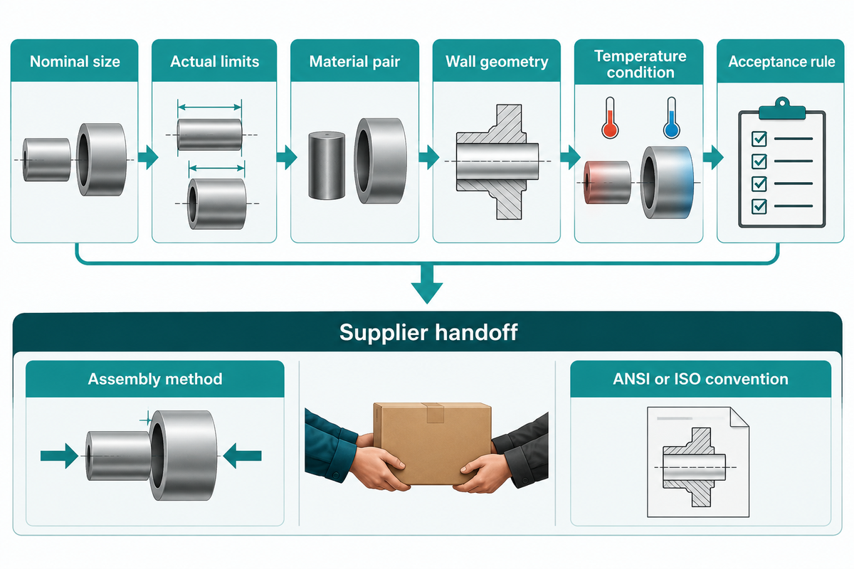
The RFQ table below is a suggested division of work, not a firm requirement. A strong, cost-effective proposal for a station starts with the joint requirements. The nominal diameter isn’t sufficient for a supplier to assess a press- or shrink-fit station. Send revision-controlled drawings, including CAD, shaft and bore limits, material and heat treatment, surface finish, coatings, engagement length, operating temperature, load case, assembly route, lubrication, intended cycle, forces and limits, inspection method, traceability and ownership for acceptance.
| Buyer supplies | Supplier proposes | Jointly validate |
|---|---|---|
| Controlled drawings, materials, variants, load and temperature requirements | Tooling, alignment, press/shrink architecture, sensors and data format | Representative samples, process window, force trace and acceptance evidence |
| Project limits and measurement decision rule | Calibration, maintenance and operator controls | FAT/SAT method, traceability, reaction plan and release owner |
The public site of SIMITCH focuses on equipment for joining sheet metal, such as servo press systems, riveting and automated assembly routes. Use the servo press systems page for a limited discussion on equipment, the riveting equipment page to discuss adjacent joining scope, and the force envelope tool for a project discussion. For an application review, provide part drawings, material stack, target load and monitoring requirements through SIMITCH contact engineering. These public pages describe public scope, not a guarantee for a specific interference fit.
What to send with the RFQ
Drawing revisions, actual material and coating, shaft/bore limits, engagement length, temperature and load case, assembly route, lubrication, force or displacement evidence required, measurement method, sample quantity, and who owns the final acceptance decision.
Frequently Asked Questions
What is an interference fit?
An interference fit has a positive size overlap before assembly: the shaft or external feature is larger than the mating hole or internal feature across the specified limits. The parts need force or thermal assistance, and the assembled joint develops contact pressure. A fit class alone doesn’t establish a safe load, force or temperature limit. The drawing still needs the nominal size, actual limits, material pair, wall geometry, temperature condition and project acceptance rule before the joint can be released.
How much interference is needed for a press fit?
There’s no universal value. Calculate the smallest shaft minus the largest bore for minimum interference, and the largest shaft minus the smallest bore for maximum interference. Check retention at the low end and stress, clearance loss and assembly damage at the high end. Material, wall thickness, temperature, friction and removal needs can change the result. Validate the chosen limits on representative parts.
What is the difference between a press fit and a shrink fit?
A press fit forces the parts together at the current temperature. A shrink fit temporarily creates clearance by heating the receiving part or cooling the inserted part, then restores interference as temperatures equalize. Both can create the same retained joint; the safer route depends on force, access, material and temperature limits. Pressing can be practical for manageable force; thermal routes can reduce mechanical loading while adding heat, cooling and handling controls.
What is H7/p6 in an interference-fit drawing?
H7/p6 is an ISO-style hole-and-shaft tolerance callout. It identifies tolerance zones for a nominal size, but the realized interference still depends on the size range, actual feature limits, form, surface condition, material, temperature and drawing convention. Confirm the governing standard and calculate the resulting minimum and maximum values. It does not establish whether the surrounding hub can withstand assembly stress.
How do you calculate interference-fit assembly force?
First calculate the dimensional interference and use an appropriate elastic contact-pressure model. A simplified sleeve-bearing relationship uses force as pressure times contact area times friction coefficient, but friction, lubrication, alignment, lead-in geometry, deformation and pressure distribution can change the measured result. Treat the equation as a screening relationship and validate it for the actual joint.
Can interference fits cause bearing or shaft damage?
Yes; too little interference can allow creep, fretting or vibration, while too much can raise stress, crack a ring, reduce internal clearance or make assembly force excessive. Bearing guidance is product- and geometry-specific. Check load direction, seat limits, operating temperature, clearance, wall geometry and the high and low tolerance extremes. A bearing manufacturer table is a product-specific starting point, not permission to transfer the fit to a different material or housing.
What should I ask an interference-fit equipment supplier?
Ask what tooling, alignment, force range, stroke, thermal route, sensors, traceability, calibration, sample trials, maintenance and acceptance tests are included. Provide controlled drawings, materials, limits, engagement length, temperature, load case and measurement rules. Make supplier-owned and buyer-owned responsibilities explicit before comparing quotations. The request should also state how representative samples, force traces, calibration, tooling changes, FAT/SAT and rework decisions will be handled.
References & Sources
This guide references public standard and equipment instruction summaries, metrology and engineering research. ISO fit standards are referenced by scope; licensed tables and the latest drawing standard define production values. SKF, NSK and GGB statements are manufacturer attributed. The GUM and VIM definitions, summarized by NIST, describe measurement uncertainty. They do not set an interference-fit acceptance limit. SIMITCH’s public equipment scope is the only claim made. No private plant data, customer trial, universal interference number or guaranteed press performance is claimed.