Get in touch with Suzhou Simitch Machinery Co., Ltd Company

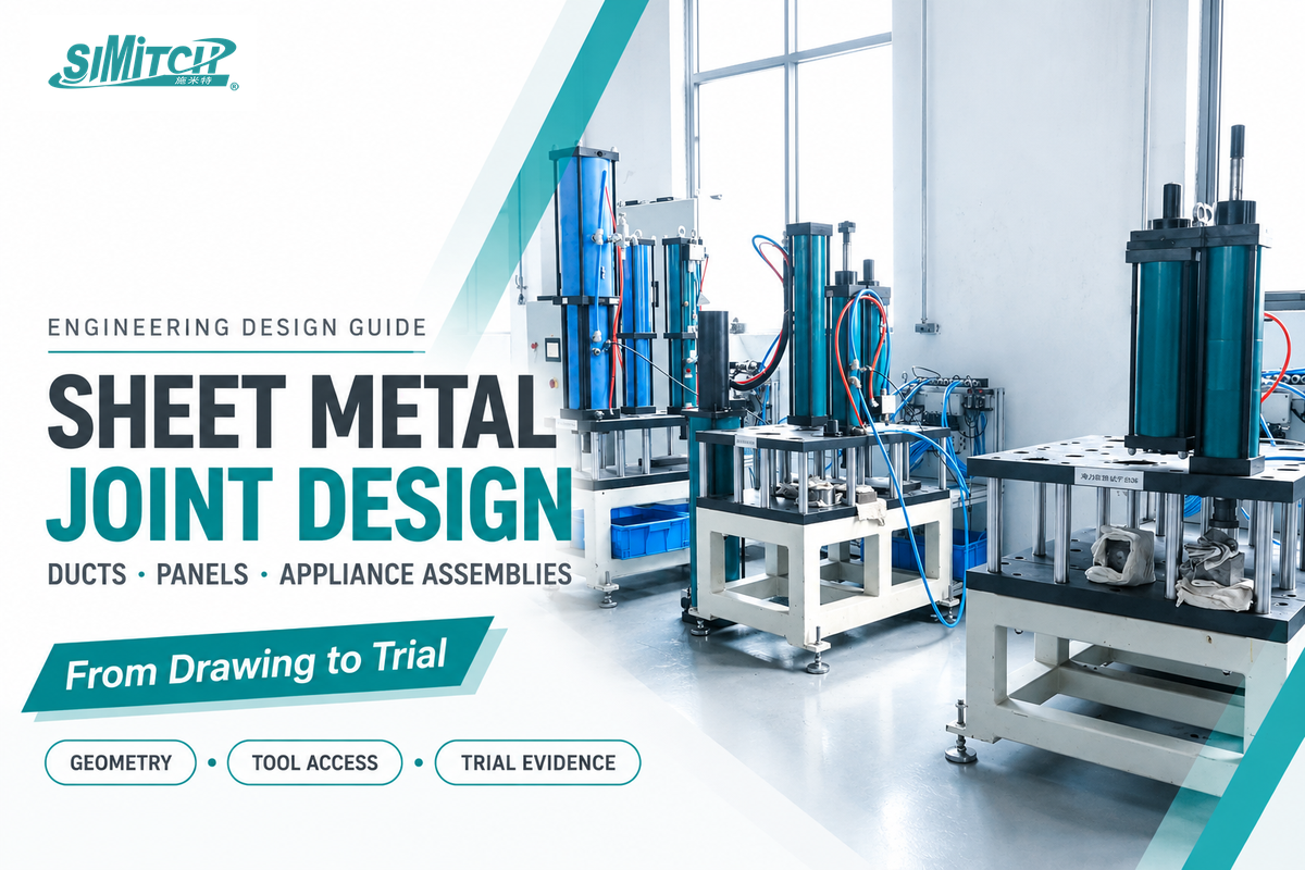
Sheet metal joint design defines how sheet edges meet, where loads cross the connection, and how the parts can be assembled. The first thing to consider is the shape, and then the size of the joining feature. Choose the geometry before sizing the joining feature: a duct seam, a permanent appliance chassis and a removable cover perform different jobs, even when they use the same material.
This design guide is for product engineers preparing drawings, manufacturing engineers checking assembly access, and quality teams agreeing on trial acceptance. When designing sheet metal products, start with the defined function and load path, check the formed part against the real tool envelope, and qualify representative samples before releasing a production drawing that other teams will have to manufacture and inspect.
Quick design summary
- Geometry describes the arrangement; a joining method describes how the connection is made.
- Overlap provides space for a feature, but doesn’t by itself establish joint strength.
- Check punch, die, fixture and removal paths at the assembly step where joining occurs.
- Keep mechanical retention, sealing, service access and other product functions as separate acceptance requirements.
Match Joint Geometry to the Job
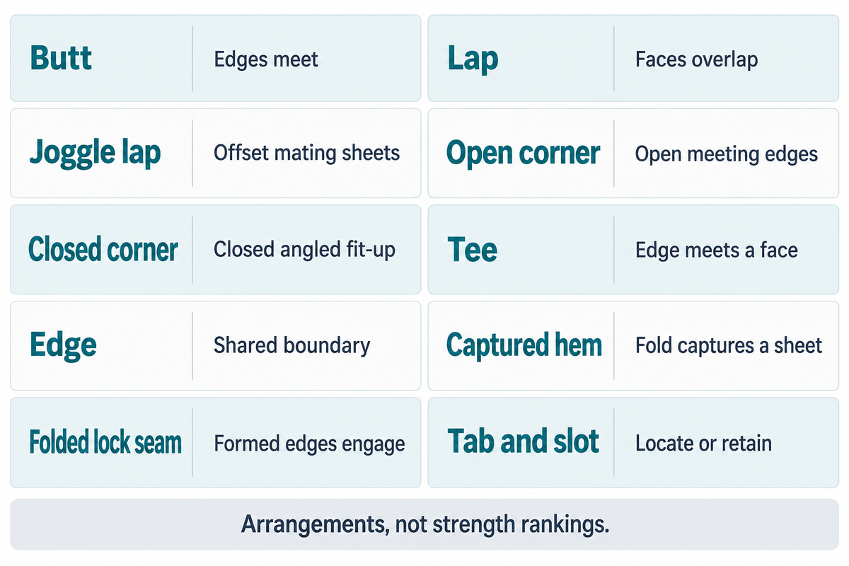
Joint geometry determines how two parts connect, and the location of a joining feature. A butt joint joins metal edges. A lap joint joins faces. A corner joint changes the load path. Choose a joint type that leaves space for the selected process, adjacent bends and the finished assembly’s service condition.
What are the different types of joints used in sheet metal?
Common types include butt, lap, corner, tee and edge arrangements, with formed variations such as joggle laps, captured hems, lock seams and tab-and-slot details. These types of sheet metal joints describe shapes. Welding, riveting and clinching are common methods for joining sheet metal; several methods can use the same shape.
| Geometry | Arrangement and useful function | Drawing question |
|---|---|---|
| Butt | Edges meet in approximately the same plane; useful for a continuous skin. | How are fit-up, backing and the required weld profile controlled? |
| Lap | One sheet overlaps another; provides a face for local joining features. | Will eccentric loading open the overlap? |
| Joggle lap | An offset accommodates the mating sheet, bringing outer faces closer to flush. | Does the offset tolerance preserve contact and surface alignment? |
| Open corner | Angled sheets leave an opening at their meeting edges. | Can the specified welding method reach and fill the intended joint? |
| Closed corner | Sheet edges meet at an angle with a closed fit-up. | How will edge position and the finished corner be inspected? |
| Tee | The edge of a bracket meets another sheet’s face. | Where will the bracket’s bending load enter the panel? |
| Edge | Adjacent or turned edges meet along a shared boundary. | What feature actually retains the components? |
| Captured hem | A folded edge captures a second component. | How are capture, local gap and finish controlled? |
| Folded lock seam | Complementary formed edges engage along a seam. | Which profile retains the seam, and which detail seals it? |
| Tab and slot | A tab locates parts before final joining, or provides designed retention. | Is the tab an assembly locator or a qualified retaining feature? |
Joint geometries are synthesized for drawing review; the rows aren’t strength rankings. A hem on a single flat sheet may simply protect or stiffen its edge. It becomes an assembly joint when it captures another part. Similarly, a loose locating tab doesn’t replace a retaining feature.
For a welded enclosure corner, state the weld joint and the finished profile rather than just saying “join edges.” Lap joints between two sheet metal parts may contain riveted joints or clinches, depending on the material and access. The broader comparison of sheet metal fastening methods covers available options; the drawing still needs to show the geometry of the joint.
The various types of joints in sheet metal require different views on the drawing: a lap needs overlap and feature locations, while a formed corner needs enough sectional detail to show how the edges actually meet and where the joining operation will take place.
Trace the Load Before Setting Overlap and Edge Distance
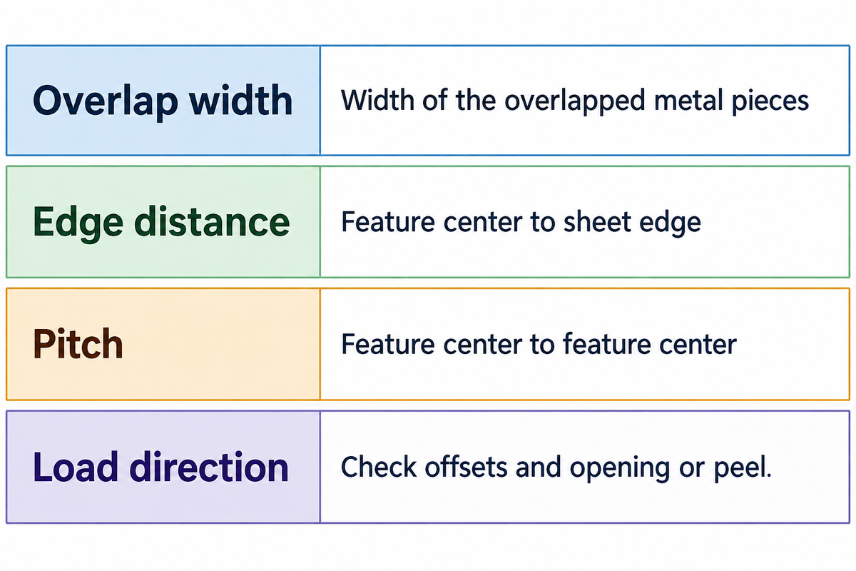
Edge distance and joint spacing should be consistent with the actual load path and selected joining method. Draw the line of force and any offsets on the assembly. A feature loaded mainly in shear may open or peel when the finished panel flexes about an unsupported edge.
Consider a thin sheet bracket attached to a flexible panel. Pulling the bracket away from the panel creates an opening action near the first joint. Moving this point and/or supporting the panel may solve the problem more appropriately than simply adding more points along the weak flange. This is a design review case and not a measured load rating case.
Dimension three items. First, the overlap width of the metal pieces. Second, the distance from the center of a feature to the sheet edges. Last, the pitch between centers of features. Determine which edge of the joint and datum each dimension is using. Equal overlap widths can still leave different edge distances if the feature is offset.
How much overlap is needed in a sheet metal lap joint?
Provide enough overlap to accommodate the tool or fastener geometry, edge distance and qualified load carrying detail. Obtain input for actual grade, thickness and stack. A universal multiple of sheet thickness can’t account for all lap joints because local tooling and loading vary.
A fastener maker’s minimum installation requirement is one input, not the complete assembly. The minimum may address hole or feature formation, while proper joint design also addresses pull-through, flange opening and cyclic movement. Ask the supplier to mark its required envelope on the same drawing being used for the structural review.
For bonded overlaps, the adhesive-design guide by Edward Petrie explains why increasing overlap depth doesn’t always produce a corresponding strength increase. That’s an adhesive-specific warning about load distribution, not a numerical rule for clinching. For two or more metal sheets, compare candidate details with the same load direction and acceptance basis.
When an assembly needs several joining points, do not multiply one coupon’s peak load by the point count and call the result allowable assembly load. Weak joints can originate in the surrounding sheet rather than the joining feature, hence, along with the joining pattern, the test arrangement, and supports must be defined, so that the load can reach the required points.
Make Room for Tools, Bends and Tolerance
Access must be evaluated on the formed sheet metal parts in their actual joining fixture. Consider the complete punch-side and reaction-side envelopes, approach direction, reach, and withdrawal path. A clear feature center on a flat blank can become inaccessible after a return flange is bent or a clamp is added beside it.
“Clinching requires open flanges with good access to both sides for the tooling”
Service access must be separate from installation access. PEM’s illustrated self-clinching installation places the fastener and sheet on an anvil before parallel squeezing with a punch; the mating piece is attached afterward. The mating part is added later. Service access therefore doesn’t describe the envelope of installation.
How do I design joints to handle tolerance variation?
Locate the joining feature from an agreed datum, combine the relevant dimensional extremes, and compare that envelope with the tool and fixture at the joining step. Keep positional clearance separate from contact-gap and strength requirements. ASME Y14.5-2018 (R2024) provides the drawing language for dimensioning and tolerancing; application-specific tool sizes still come from the tooling design.
Worked example: screen a tool footprint
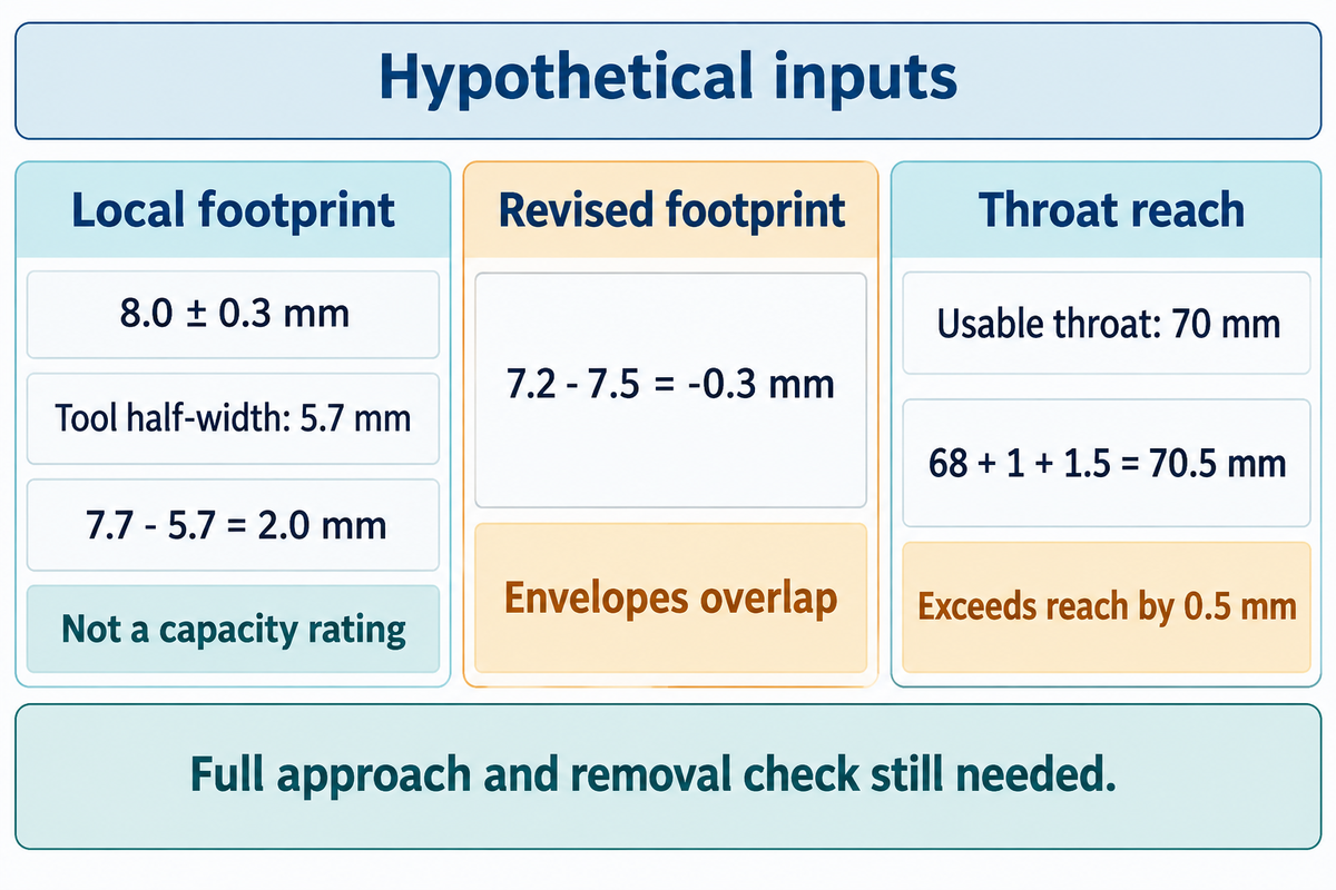
Hypothetical inputs: assume a straight obstruction beside a tool centerline, a center-to-obstruction distance of 8.0 ± 0.3 mm, and a maximum projected tool half-width of 5.7 mm. The screen is one-dimensional and excludes angular motion, deflection and other clearances.
- Minimum center-to-obstruction distance: 8.0 − 0.3 = 7.7 mm.
- Remaining geometric space: 7.7 − 5.7 = 2.0 mm.
- If a revised layout instead gives 7.2 mm minimum distance and a 7.5 mm maximum half-width, the result is −0.3 mm: the envelopes overlap.
The first result gives 2.0 mm clearance, which isn’t a minimum acceptable flange width or proof of joint capacity. In the second layout, tooling or assembly sequence must be changed before trial. A full three dimensional check is needed for approach and removal.
Reach can fail independently. With a hypothetical 70 mm usable throat, a target depth of 68 ± 1 mm and a 1.5 mm fixture offset require 68 + 1 + 1.5 = 70.5 mm at the extreme. That layout exceeds the assumed usable reach by 0.5 mm even though its local tool footprint might fit.
For design for manufacturability, review the sequence early in the design phase: joining before a closing bend may preserve access, but the following bend also has to be feasible with the installed element. For the sheet metal design release in custom sheet metal fabrication, send the formed model and fixture concept with the drawing, rather than requesting a quote from a blank outline.
Design Duct Joints for Retention and Sealing
Separate details are required for mechanical retention and air leak paths for Duct joint. Mark longitudinal seams along the airflow direction and transverse connections between duct sections. Also, illustrate how changes in section of a duct and duct penetrations remain sealed. A joint can hold the duct in position while a continuous leak path is maintained around the fasteners or folds.
The U.S. Department of Energy’s Seal Ducts With Mastic job aid addresses fastening and sealing separately in residential weatherization; use the project’s actual duct specification for pressure, leakage class, permitted materials and construction details.
A hypothetical galvanized duct transition shows a longitudinal lock seam closing the shell, while a transverse flange closes the joint to the next section. The engineer shows and labels the retaining detail, the seal path across each corner and the installed orientation. Quality checks for mechanical engagement and the leakage result, separately. A closed seam doesn’t indicate an answer to both these questions.
Seam joints and simple edge joints are kept distinct in the drawing legend. Pittsburgh and snap-lock profiles use formed edges of certain profiles; specify the intended profile instead of using any folded edge indiscriminately. For equipment review, the HVAC and home appliance clinching application page identifies the relevant assembly context.
Keep interfaces with specified movements and break-away. Sealing of connections must account for shafts moving and thermal expansion and must not conflict with fire/smoke damper product listings, as explained in the ASHRAE 2016 chapter on duct construction. For those interfaces, product instructions of the specified and actual product must be followed; a generic permanent joint may alter their function.
Separate Permanent Structure from Appliance Service Panels
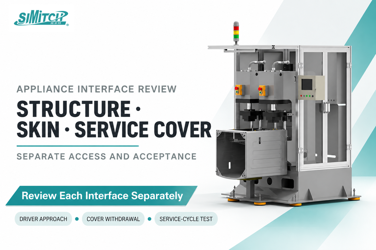
Appliance sheet metal assemblies should differentiate the permanent load-carrying structure from cosmetic skins and removable service covers. Each interface should have its own retention, appearance and removal requirements. A permanently installed threaded insert can support a removable service cover, and a clinched chassis flange remains closed during normal operation. Drawing and inspection details should be done separately for these interfaces.
Assume an appliance side panel has a painted skin. A forming mark that’s acceptable within the chassis may show through the skin. The design team identifies the cosmetic face, permitted marking zone and finish sequence before choosing a joining process. Moving the attachment behind a return flange may affect tooling access, so the formed assembly should be checked again.
A second hypothetical assembly uses a permanent frame with a rear-mounted service cover held in place by a removable screw. Withdraw the cover to access the service part. Show the driver’s approach, clearances, how the cover is withdrawn and what prevents adjacent cables and gaskets from being trapped during refitting. Agree the required service-cycle test instead of assuming that a threaded fastening can be reused indefinitely.
Where a metal panel is part of the protective bonding path, electrical continuity must be specified separately. Issues relating to grounding paths and the applicable equipment, with defined conditions and exceptions, are addressed in 29 CFR 1910.304(g)(5), (6). Mechanical tightness alone doesn’t define continuity; the applicable product design and test requirements must govern the bonding detail.
For joining dissimilar metals, document the material combination, coatings and exposure. Hybrid joining methods don’t always prevent corrosion. A sheet metal fastening detail that adds adhesive, an isolating layer or a seal needs its own interface, cure and environmental requirements. Review those layers as part of the stack rather than as a shop-added unrecorded modification.
Detail Clinched Joints Around the Real Sheet Stack
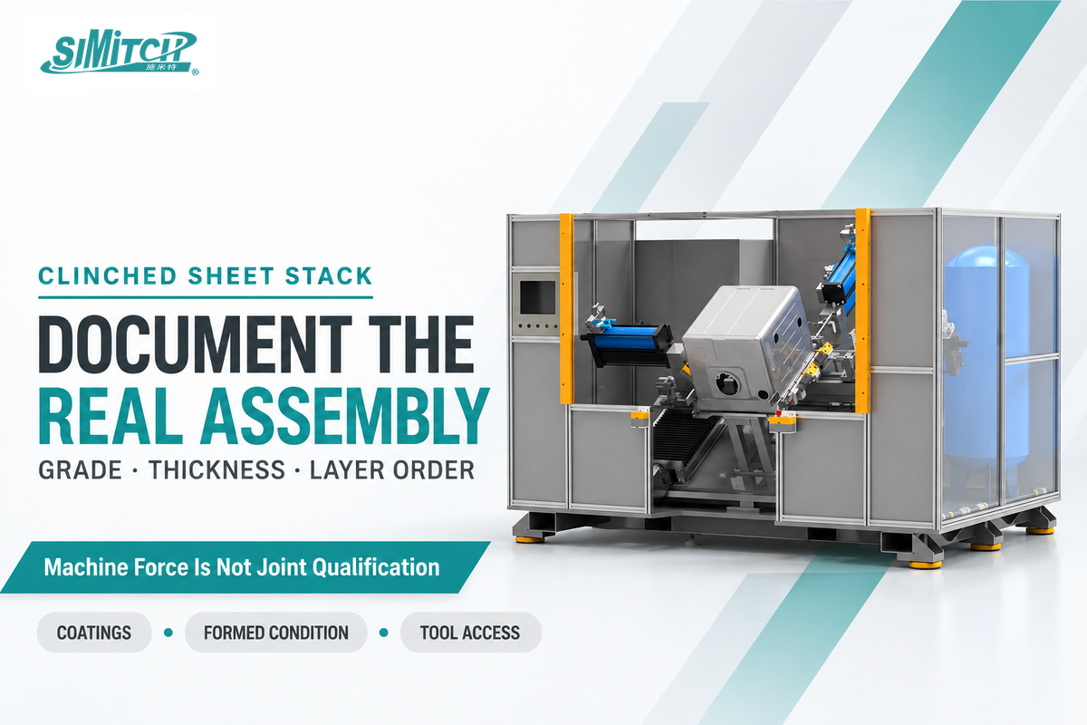
Document the order, formed condition and coatings of each sheet, as well as the grade of the sheet, for a clinched connection. The tool must form an interlock with the other layers of the stack while both sides remain accessible. Machine force alone does not specify the resulting local geometry or demonstrate that a different material combination will carry the required load.
Sheet-to-sheet clinching deforms the metal sheets into a local interlock without an added rivet. Self-clinching hardware instead installs a separate component into sheet material. Self-piercing riveting uses a rivet and a supporting die; its self-piercing riveting equipment therefore follows a different tooling and consumable route. Keep those connections separate in the joint legend.
According to Groeger and colleagues’ 2021 original study of thermoplastic-composite/metal clinching, neck thickness, undercut and bottom thickness are separate geometry fields. Note the various materials and conditions of the experiment. Use this to locate a relevant section and test record, rather than assume measured loads can be transferred to an all-metal appliance assembly.
- Identify each layer by grade and thickness range, with punch-side and die-side orientation.
- Mark prior bends, drawing or other forming near the point.
- Show the tool envelope, flange support and allowable surface marking.
- Connect each proposed point to a load direction and an agreed acceptance method.
Clinching eliminates the need for welding heat input, but deformation can still affect the surface layers and local geometry. Spot welding requires access to electrodes and a qualified weld schedule, and therefore, changes the assumptions made in the drawing. While comparing welding or fastening to clinching, keep the production stack in the trial. The sheet metal joining method must comply with the recorded sheet metal materials, and the conditions it’s in after forming, as opposed to just citing a common sheet metal grade.
For a feasibility check, provide your dimensioned drawings to the clinching machines and application review team. Request the proposed tooling arrangement and trials before finalizing the selection of an equipment family as a qualified joining detail. For the proposed innovations in sheet metal joining, request the same baseline and acceptance checks to allow a new process to be compared with the existing joining detail.
Qualify the Joint in the Direction It Will Be Loaded
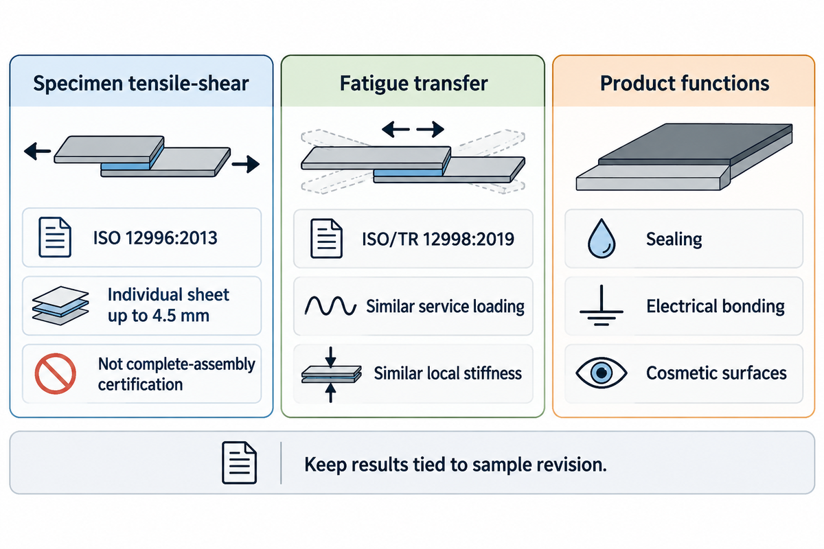
Qualification of a joint should maintain the production stack and relevant load and failure mode in the test record. A tensile-shear coupon evaluates a defined test specimen and fixture. Other checks may be required. Agree the acceptance criterion before samples are made to allow buyer and supplier to assess the same function.
ISO 12996:2013 specifies specimen geometry and tensile-shear testing of single mechanical joints, up to an individual sheet thickness of 4.5 mm. Its public record reports confirmation in 2024. The test method is not applicable to specified civil engineering applications; assessing a test specimen does not guarantee a complete duct or appliance.
According to the abstract of ISO/TR 12998:2019 fatigue, direct transfer of results is limited to similar service loading and local stiffness around the joint. A flexible production panel and stiff laboratory coupon, which contain the same joining feature, may still require additional assessment.
Also record environmental conditioning. Harzheim et al’s abstract on corrosion-and-fatigue research cites a particular aluminum-steel clinched joint where the contact state and fatigue behavior were changed due to exposure to corrosion. This indicates that recording exposure conditions is warranted; this isn’t necessarily a case of improved or reduced service life prediction.
Request the specimen drawing, material identification, stack orientation, loading direction, test method, individual test results and failure photographs. Add the product-level checks needed for sealed joints, electrical bonding or cosmetic surfaces. When comparing the methods used, keep images of test sections and loads tied to the same sample revision; otherwise, a useful photograph of one sample can be mistakenly referenced to support a conclusion about another sample.
Release a Drawing That a Supplier Can Trial
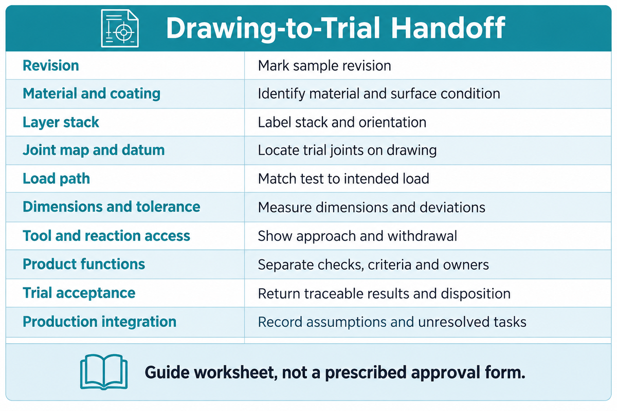
A useful trial brief fixes the drawing revision, sheet stack, joint locations and required evidence before samples are made. Assign an owner to each missing input and require the supplier to return marked drawings and traceable results. Still selecting the right joining method leaves access and acceptance questions which should be named in the quotation.
The 10-Field Drawing-to-Trial Handoff below is a proposed worksheet for preparing that brief. It incorporates geometry, manufacturing, and quality in a single exchange. Product-specific safety, electrical, environmental and special-interface reviews remain separate responsibilities; identify their owners in the brief rather than assuming a mechanical sample test covers them.
| Field | Input owner and required information | Expected return evidence |
|---|---|---|
| 1. Revision | Design: drawing/model revision and approved deviations. | Supplier marks the revision used for every sample. |
| 2. Material and coating | Materials/design: grade, thickness range and surface layers. | Sample material identification and recorded surface condition. |
| 3. Layer stack | Design/manufacturing: layer order and joining-side orientation. | Labelled stack sketch and sample orientation. |
| 4. Joint map and datum | Design: point/seam locations and reference features. | Marked drawing locating the trial joints. |
| 5. Load path | Design: direction, support condition and service loading. | Proposed test arrangement matched to the intended load. |
| 6. Dimensions and tolerance | Design: overlap, edge distance, pitch, gaps and tolerance basis. | Measured sample dimensions and stated deviations. |
| 7. Tool and reaction access | Manufacturing: formed model, clamps, reach and assembly sequence. | Tool-envelope drawing with approach and withdrawal paths. |
| 8. Product functions | Product owners: sealing, appearance, service; applicable bonding, environment and movement/breakaway interfaces. | Separate functional checks, criteria and responsible reviewers. |
| 9. Trial acceptance | Quality/design: sample plan, test methods and acceptance criteria. | Traceable results, failure modes, photos and disposition. |
| 10. Production integration | Manufacturing/procurement: production volume, variants, takt and handling scope. | Equipment/fixture assumptions, exclusions and unresolved tasks. |
Worksheet developed for this guide; it isn’t a standard-prescribed approval form. For example, if a supplier moves a point to gain tool access, design reviews the revised edge distance and load path before quality accepts the sample; carry the change into the drawing revision used for production.
Simitch specializes in developing smart joining technologies and system level solutions for home appliances, and HVAC. Check out Simitch’s joining equipment background to learn more about the company. You can request a duct or panel trial by sending a drawing, representative stack and proposed acceptance checks through the sheet metal assembly enquiry or discuss your joint drawing.
Sheet Metal Joint Design Questions
What is the strongest sheet metal joint?
No joint is strongest across every material, geometry and load direction.
Compare candidates using the same stack, specimen arrangement and acceptance criterion. Use ISO 12996:2013 for applicable single mechanical-joint tensile-shear specimen tests. A weld loaded in shear, a clinch loaded in peel and a screw loaded in pull-through answer different questions. The strength of the weld alone also omits the surrounding sheet’s response. For a flexible panel, include local bending and the real support conditions in the qualification plan.
Can different metals be joined in sheet metal fabrication?
Different metals can be joined when the selected process and interface suit the actual material pair.
Specify each grade, coating and thickness, then review deformation, thermal effects and environmental exposure. Mechanical attachment avoids some welding compatibility problems but does not eliminate galvanic concerns. If hybrid joining includes an adhesive or isolating layer, identify its placement and requirements in the stack. Test the intended interface under representative conditions rather than approving it from the material names alone.
How does joint design affect strength and cost?
Joint geometry changes load transfer, tool access and the work needed to produce an accepted assembly.
A narrow flange can require different tooling or an earlier joining step. An inaccessible fastener can add handling, while a visible weld can add finishing work. Compare quotations against the same drawing, inspection scope and production volume. Include fixtures, sample qualification and service requirements; the price of one joining feature does not describe the cost of the completed panel.
Does welding thin aluminum always cause warping?
Warping is a risk, rather than an inevitable result of every aluminum weld.
Fit-up, restraint, heat input and the qualified procedure affect distortion. For welding sheet metal, review the actual geometry and permitted surface movement with the fabricator before approving the joint. Thin sheet metal needs particular attention to support and the finishing sequence.
When should I use stitch welding instead of a continuous weld?
Use intermittent welding only when the required strength, sealing and service conditions permit a discontinuous weld.
A continuous air or liquid barrier may need a different detail from an intermittently attached stiffener. Set the weld length and spacing through the approved design and procedure, rather than a general pitch rule. Compare access for welding, local distortion and inspection needs. TIG welding, metal inert gas welding and laser welding have different equipment and fit-up needs; specifying only the process name does not establish filler metal, weld quality or an acceptable schedule for the assembly.
What is the minimum bend radius for sheet metal?
The minimum usable bend radius depends on the exact grade, temper, thickness and forming process.
Agree the radius with the fabricator’s material and tooling data. Then check its effect on the adjacent joint’s flange space, contact and feature location. A radius acceptable for forming may still obstruct the joining tool.
What tolerances are achievable in sheet metal assembly?
Achievable assembly tolerances must be agreed for the actual datum system, formed parts, fixtures and joining process.
Start with the dimensions that control fit and function. Ask the supplier to distinguish blank tolerances, bend variation and final assembled measurements. A precision sheet metal component does not automatically create an equally precise assembly when several bends and locating features accumulate variation. During the design stage, identify how the parts are located before joining and measured afterward. Record any fixture-induced restraint so the inspection does not hide movement that appears after the assembly is released.
References & Sources
- ASME, Y14.5 Dimensioning and Tolerancing, public scope.
- The Fabricator, Spot weld, fasten, or clinch?, supplier-authored guidance by Byron Selorme.
- U.S. Department of Energy, Seal Ducts With Mastic, residential job aid.
- ASHRAE, 2016 Handbook, Chapter 19: Duct Construction, public chapter.
- Electronic Code of Federal Regulations, 29 CFR 1910.304, grounding provisions within their applicable scope.
- Groeger and colleagues, Materials 14(9), 2286 (2021), original composite/metal clinching research.
- International Organization for Standardization, ISO 12996:2013, public scope and lifecycle record.
- International Organization for Standardization, ISO/TR 12998:2019, public fatigue-test scope.
- Harzheim and colleagues, Corrosion Phenomena and Fatigue Behavior of Clinched Joints (2022), University of Paderborn public abstract.