Get in touch with Suzhou Simitch Machinery Co., Ltd Company

Updated November 2026 | Technical Engineering & Procurement Guide
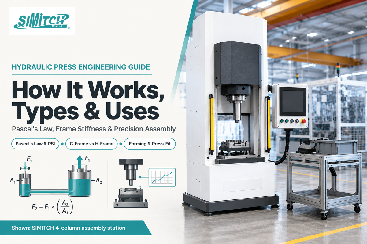
A hydraulic press uses a motorized or manual pump, an enclosed oil reservoir, and a hydraulic cylinder to multiply mechanical force using Pascal’s law. Across industrial metal forming and interference press-fitting, hydraulic presses deliver their full rated tonnage at any point in the ram stroke, with forming pressure density spanning 1 to 150 tons per square foot (The Fabricator).
A mechanical crank press develops peak capacity near bottom dead center (BDC). A hydraulic press, on the other hand, holds a controlled dwell pressure at any position in the stroke and can stop and hold anywhere in the cycle (OSHA Machine Guarding eTool). Directional valve shifts and oil decompression limit the cycle to about 30 strokes per minute (SPM), although air-over-hydraulic cylinders, electromechanical servo presses, and other controls can be employed for high-speed, low-force assembly (Assembly Magazine).
Hydraulic presses multiply force by pumping incompressible oil into a cylinder piston of area A at system pressure P (F = P × A). Choose a C-frame or H-frame shop press (1 to 176 tons) for maintenance and bearing work, a 4-column or straight-side press for deep drawing, or a servo press for monitored assembly.
Quick Specs: Hydraulic Press Engineering Benchmarks
| Force Multiplication Equation | F2 = F1 × (A2 / A1); Push Tonnage = PSI × π × (Bore / 2)2 ÷ 2,000 (MSU Physics; Firgelli) |
| Forming Tonnage Density & Cycle Rate | 1 to 150 tons/sq. ft. across full stroke; approach >1 m/sec; cycle rate <30 SPM (The Fabricator) |
| Industrial Shop Press Capacities | Benchtop: 1–15 tons; Floor Shop Press: 20–50 tons; Heavy Industrial Shop Press: 66, 110, and 176 tons (Scotchman) |
| Bed Load & Reverse Tonnage Limits | Full rated capacity requires at least 66% bed length support; blanking reverse tonnage can reach 10% to 25% and up to 50% of forward tonnage (The Fabricator) |
| U.S. Safety & Maintenance Standards | OSHA 29 CFR 1910.212 & ANSI B11.2-2013 (R2020); oil service every 2,000–4,000 operating hours (OSHA; VIGERT) |
Key Engineering Takeaways (TL;DR)
- Nameplate tonnage doesn’t apply to concentrated or eccentric dies: standard press tonnage ratings assume the load covers at least 66% of the bed length, whereas concentrating a die onto one-third of the bed can cut allowable capacity to 50% (The Fabricator).
- Rules governing mechanical power under OSHA 29 CFR 1910.217 exclude hydraulic machines, which are governed by OSHA 29 CFR 1910.212 and the consensus standard ANSI B11.2-2013 (R2020) (U.S. Federal Register).
- Return stroke force is lower than extension force: on a double-acting cylinder, the piston rod subtracts effective area on retraction, so a 2.0 in. bore cylinder with a 1.0 in. rod at 2,000 psi pushes at 3.14 US tons but pulls at 2.36 US tons (Firgelli Automations).
- Match the drive to the force-displacement window: use full hydraulic presses for high-tonnage forming, pneumohydraulic cylinders for short high-force power strokes, and servo-electric presses (0.5 to 600 kN) when assembly quality requires closed-loop force-distance curves.
How Does a Hydraulic Press Work? Pascal’s Law, Pump, Cylinder, and PSI
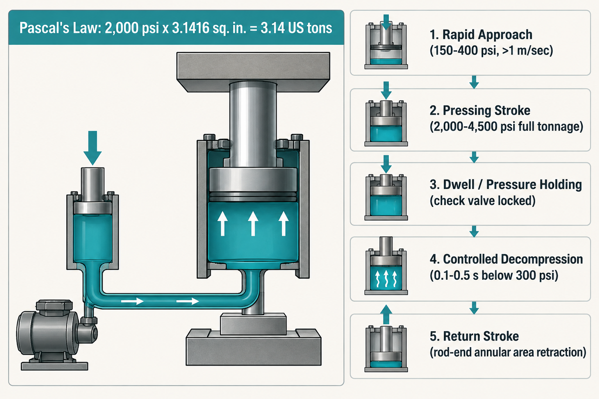
A hydraulic press multiplies force in proportion to the surface area ratio between two connected pistons, and thus delivers full rated tonnage at any point on the stroke of the ram. A narrow plunger in a hydraulic circuit can push nearly incompressible hydraulic oil into a wide cylinder bore to compress, form, or assemble workpieces ( Encyclopaedia Britannica).
An input force is multiplied by five when a slave cylinder has five times the cross-sectional area of a master cylinder (MSU College Physics). When an assembly station requires dry cleanroom operation or cycle rates above 30 SPM, engineers switch from an oil-hydraulic circuit to a servo-electric actuator.
How does a hydraulic press work?
A hydraulic press works by drawing hydraulic oil from a vented reservoir through a pump and forcing that oil into a sealed cylinder against a sliding piston and ram. Static fluid pressure (P = F / A, measured in pounds per square inch or bar) acts equally across every square inch of the piston face, so a 2,000 psi pump feeding a 2.0 in. bore cylinder (3.1416 sq. in. area) generates 6,283 lbf or 3.14 US tons of pushing force (Firgelli Automations).
Hydraulic Pump, Reservoir, Cylinder, and Relief Valve Stages
Industrial hydraulic press uses seven fundamental elements (The Fabricator). Load bearing elements include the frame and bolster table, hydraulic cylinders, and a sliding piston and ram. Fluid power is generated by a hydraulic pump (either driven electrically or manually), an oil reservoir, and directional plus pressure-control valves. Single-acting cylinders are designed to rely on heavy return springs or ram weight to retract, but double-acting hydraulic cylinders rely on oil to pressurize on the retraction stroke. Due to the cross sectional area occupied by the piston rod on the return stroke, retraction force is considerably less than tonnage on the extension stroke.
In stamping and forming cells, an industrial hydraulic press doesn’t just push down and reverse. At full tonnage, hydraulic oil compresses by roughly 0.5% per 1,000 psi while the steel frame stretches elastically. Rapidly switching a directional control valve from 3,000 psi pressing pressure to the return port releases stored elastic potential energy and causes valve spool erosion and water hammer shock. For this reason, production circuits sequence 5 distinct hydraulic stages.
| Cycle Stage | Valve & Pump State | Fluid Pressure & Ram Speed | Primary Engineering Purpose |
|---|---|---|---|
| 1. Rapid Approach (Fast Fall) | Prefill valve open from overhead reservoir; regenerative circuit active | Low pressure (150–400 psi); high speed (>1 m/sec) | Close daylight gap rapidly without sizing a massive high-pressure pump |
| 2. Pressing / Working Stroke | Prefill valve closes; high-pressure pump feeds cap-end cylinder port | Rising to rated system pressure (2,000–4,500 psi); controlled forming speed | Deliver full rated tonnage throughout the metal forming or assembly stroke |
| 3. Dwell / Pressure Holding | Pilot-operated check valve locks cap-end pressure; relief valve guards peak PSI | Constant target PSI; zero ram velocity | Eliminate sheet metal springback or cure composite molding resin under heat |
| 4. Controlled Decompression | Proportional bleed-off or decompression poppet opens for 0.1–0.5 seconds | Cap-end pressure bled down below 300 psi before main directional shift | Release compressed oil and frame stretch smoothly to prevent hydraulic shock |
| 5. Return Stroke (Retraction) | Directional valve routes pump flow to rod-end port; prefill valve reopens | Moderate pressure on annular area (Arod subtracted); fast return | Lift slide back to top dead center and purge cap-end oil into reservoir |
Frame Architectures: C-Frame, H-Frame, Four-Column, and Straight-Side Press Selection
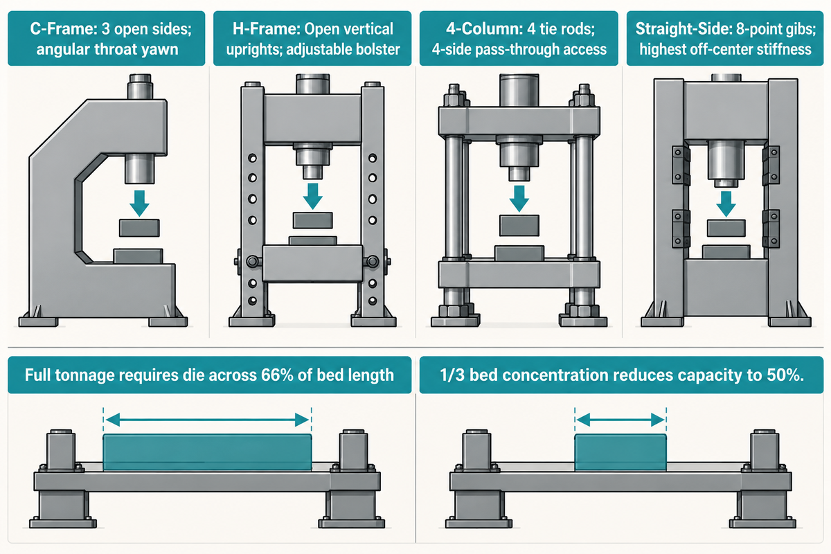
Select a hydraulic press frame by matching throat access and off-center load stiffness: open-gap C-frame presses give three-side material access for compact beds, whereas 4-column and gib-guided straight-side frames resist angular deflection under eccentric tooling (Beckwood Press).
On a centered load, a 400-ton two-connection press distributes 200 tons per connection and full tonnage capacity requires the die to span at least 66% of the bed length (The Fabricator). If progressive or multi-cavity tooling shifts the resultant load off the centerline of the press, upgrade from a single-cylinder H-frame or C-frame to an 8-point gib-guided straight-side frame.
Adjustable Bolster Plate, Bed Deflection, and Off-Center Loading
Rated press tonnage assumes the load is centered and distributed across at least 66% of the bed length; off-center or concentrated dies require tonnage derating based on the press manufacturer’s deflection chart (The Fabricator). If a small coining die covers only one-third of the length of the bolster plate, tonnage can be reduced to 50% of the nameplate capacity to keep the bolster beam deflection within elastic limits. On open-gap C-frame presses, heavy loads cause angular throat yawning, which in turn, tilts the punch relative to the die. Utility H-frame shop presses eliminate throat yawning, but as machinists on Practical Machinist note, an unguided single cylinder in an H-frame still cocks sideways under eccentric bending loads where tooling demands bed bow under 0.0015 in. per foot.
To keep buyers from matching tonnage without providing structural guidance, use the Frame-and-Stroke Press Architecture Selection Matrix below. This 9-row engineering matrix pairs each press architecture with its guidance mechanism, bed access, off-center load rating, and primary industrial use.
| Press Type & Frame Category | Capacity Tier | Slide Guidance & Access | Off-Center Load Resistance | Primary Process & Application |
|---|---|---|---|---|
| 1. Benchtop C-Frame Press | 1 to 15 tons | Cylinder rod or 2-post guide; 3 open sides | Low (centered small tooling only) | Small bearing press-fit, staking, electronic connector assembly |
| 2. Floor Guided C-Frame Press | 20 to 150 tons | Ram gibs or dual guide rods; 3 open sides | Moderate (angular throat yawn at peak load) | Strip feed punching, shallow forming, robot-tended trim dies |
| 3. Utility H-Frame Shop Press | 10 to 50 tons | Unguided single cylinder; pin-adjustable bolster | Low (ram tilts under eccentric load) | Auto repair, pressing bearings, bushings, u-joints, pin removal |
| 4. Heavy Industrial H-Frame Press | 66 to 176 tons | Movable workhead + winch-adjusted heavy bolster | Moderate (axial load over workhead position) | Heavy shaft straightening, fabrication bending, keyway broaching |
| 5. 4-Column (4-Post) Utility Press | 25 to 250 tons | 4 cylindrical tie rods with graphite-bronze bushings; 4 open sides | Good (resists front-to-back and left-to-right tilt) | Compression molding, die casting trim, pass-through conveyor lines |
| 6. Deep-Draw 4-Column Cushion Press | 150 to 1,500 tons | 4 pre-stressed tie rods + lower hydraulic die cushion | High (4-corner leveling or cushion balance) | Deep drawing cookware, pressure vessels, automotive body panels |
| 7. Straight-Side Gib-Guided Press | 200 to 3,000+ tons | 8-point square bronze/hardened steel gibs; front/rear access | Highest (minimal lateral or angular slide deflection) | Progressive die stamping, heavy blanking, aerospace hot forming |
| 8. Hydro-Pneumatic Assembly Press | 2 to 50 tons | Anti-rotation guide rod or 2-column C-frame | Moderate (short high-force intensification stroke) | Sheet metal clinching, riveting, piercing, fastener insertion |
| 9. Servo-Electric Precision Press | 0.05 to 60 tons (0.5–600 kN) | Ball/roller screw + anti-deflection C-frame or 2-column frame | High within rated throat envelope (±0.005 mm repeatability) | Monitored bearing/bushing press-fit, rotor assembly, EV cell stacking |
Sources: Beckwood Press, Scotchman Industries, The Fabricator, and Assembly Magazine.
Hydraulic Shop Press Models: Benchtop Hydraulic, 20 Ton Hydraulic, and Floor Shop Press
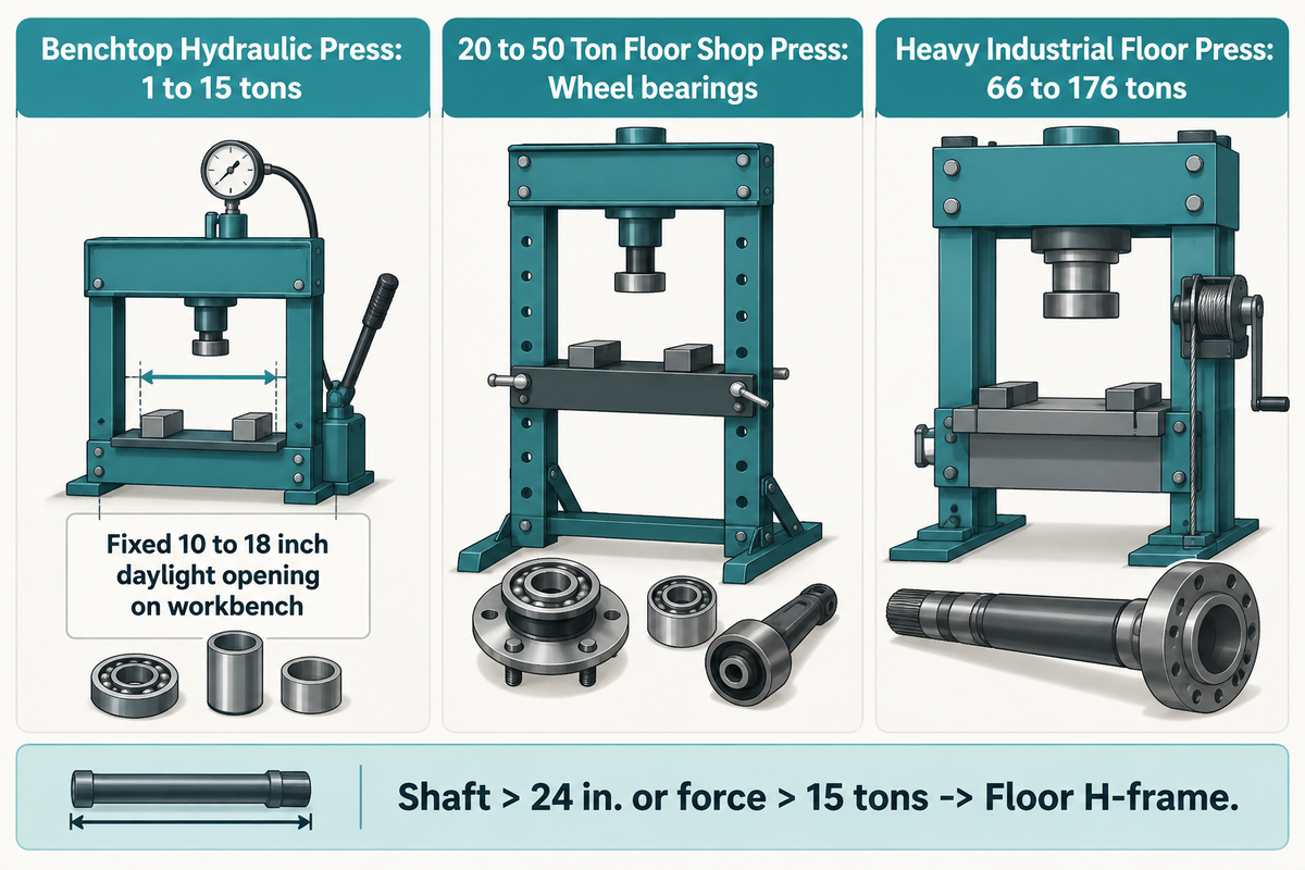
Match your hydraulic shop press to workpiece height and force capacity: a benchtop hydraulic unit supplies 1 to 15 tons for compact workbench parts, a 20 ton hydraulic floor unit handles passenger vehicle wheel bearings and suspension bushings, and heavy industrial floor models deliver 66 to 176 tons (Scotchman Industries).
When the length of the shaft exceeds 24 inches or a press force exceeds 15 tons, use a floor standing H-frame rather than a bench frame.
What is the difference between a shop press and a bench top hydraulic press?
A benchtop hydraulic press is attached to a workbench with a fixed 10 to 18 inch daylight opening and a 1 to 15 ton cylinder, and a floor shop press stands 60 to 75 inches on the shop floor with a pin-adjustable bolster bed spanning 20 to 176 tons of capacity. The workbench assembly design uses an open H-frame or C-frame structure. Long transmission shafts and bulky weldments, like truck axles, can’t fit through a bench frame, and floor shop presses are used to accommodate those types of applications.
Maintenance and fabrication shops categorize their hydraulic shop press equipment into three capacity tiers:
- Compact Footprints
For 1 to 15 ton benchtop hydraulic units, a compact footprint (16 to 24 inches wide) bolts to a steel workbench and is powered by hand pumps or air-hydraulic foot pumps. This compact configuration is economical for small electric motor armatures and precision instrument bushings.
- In the 20 to 50 ton floor tier, the standard 20 ton hydraulic press serves as the primary workhorse in an auto repair bay. Operators position removable arbor plates on a multi-position pin-locked bed to support hubs and shafts.
- In 66 to 176 ton heavy-duty industrial units, units such as Scotchman’s PressPro 66, 110, and 176 ton models use a powered pump and a sliding head and cable-winch table to straighten heavy plates, push large broaches, and form thick bar stock (Scotchman Industries).
Drive Systems Compared: Air Hydraulic, Pneumatic Shop Press, Mechanical, and Servo-Electric
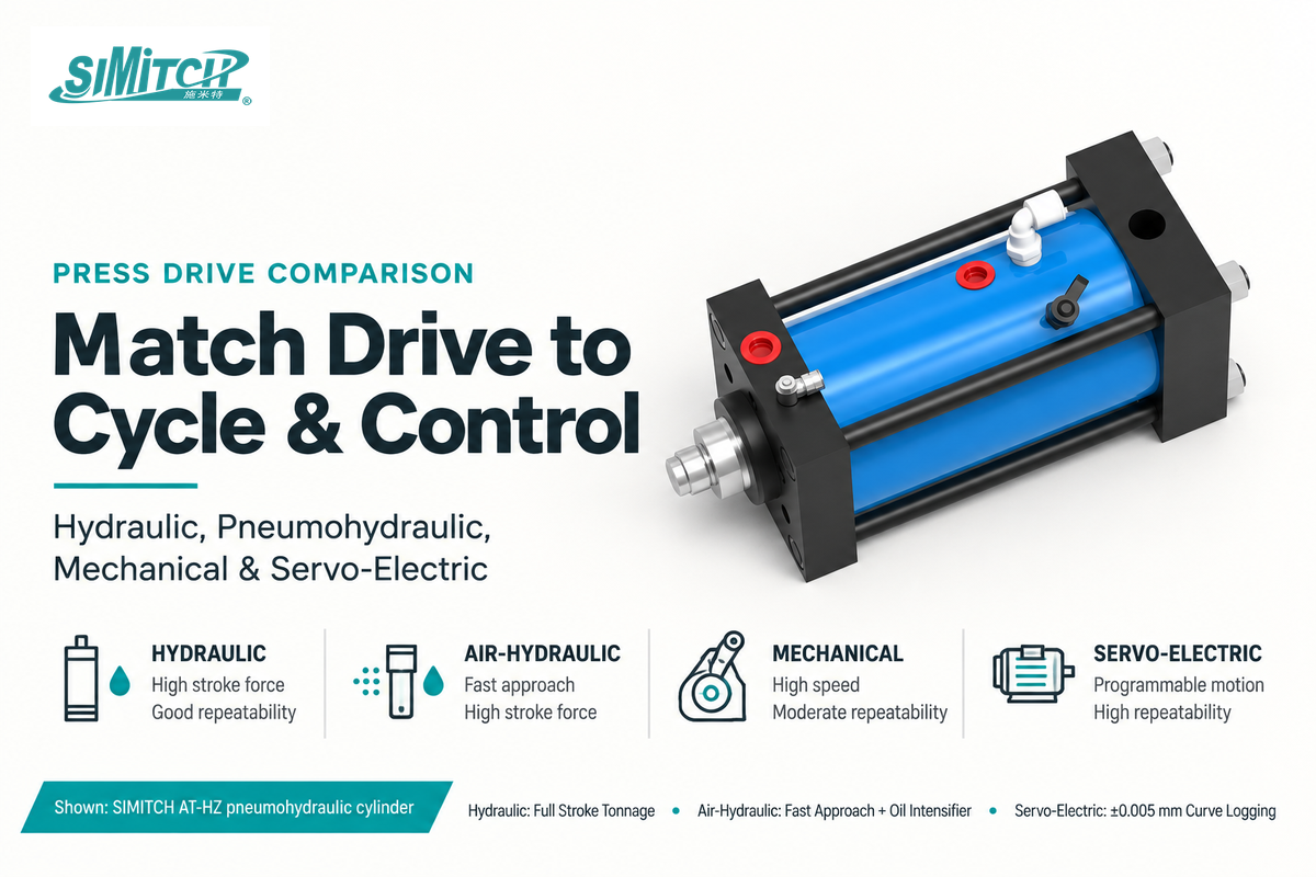
Certain drives record stroke, speed, and load data and combine them with quality traceability. Full hydraulic presses deliver full rated tonnage at any stroke position below 30 SPM. Air hydraulic drives pair fast pneumatic approach with an oil-intensified power stroke. Mechanical flywheel presses run high speed blanking. Servo-electric presses provide oil-free force-distance monitoring (The Fabricator, Assembly Magazine).
When an assembly requires full force-displacement curve logging at ± 0.005 mm repeatability without hydraulic fluid leaks, use an electromechanical servo press.
Manual, Air Over Hydraulic, Pneumatic, or Electric: Which Power Type Do You Need?
Use a manual hand-pump press for maintenance under 10 cycles per day, an air hydraulic (air-over-hydraulic) press when shop compressed air (90 – 120 psi) is available for hands-free medium tonnage pressing, a direct pneumatic shop press for fast light-duty cycles under 5 tons, an electrically driven hydraulic power unit for high tonnage forming, and a servo-electric press for closed loop assembly. Engineers comparing servo, pneumatic, and hydraulic press drives discussed whether full force was required throughout the stroke or only during the last few millimeters of contact.
In sheet metal joining and fastener insertion, pneumohydraulic drive cylinders bridge the gap between pneumatic speed and hydraulic tonnage. A pneumohydraulic cylinder uses ordinary shop air for a rapid, low-force approach stroke, until the punch contacts the work piece. It then uses an internal oil-intensifier piston to create 10 to 50 tons of hydraulic forming force in a short, powerful stroke, without requiring an external hydraulic pump or reservoir.
| Drive System | Force Across Stroke | Typical Cycle Speed | Position Repeatability | Best-Fit Industrial Process |
|---|---|---|---|---|
| Conventional Hydraulic Press | Full rated tonnage at any point in stroke | <30 SPM (limited by valve shift & decompression) | ±0.05 to ±0.25 mm (positive stops or proportional valves) | Deep drawing, heavy plate forming, compression molding, high-tonnage forging |
| Air Hydraulic / Hydro-Pneumatic | Low air approach force + full intensified oil power stroke | 20 to 50 SPM | ±0.05 to ±0.15 mm | Sheet metal clinching, riveting, piercing, bushing insertion without a hydraulic power unit |
| Direct Pneumatic Shop Press | Constant force limited by air line PSI × cylinder bore | 30 to 80 SPM | ±0.10 to ±0.50 mm (air compressibility) | Light-duty staking, crimping, spring compression under 5 tons |
| Mechanical Flywheel Press | Rated tonnage available only near BDC (1/3 capacity at 1/3 stroke) | 40 to 600+ SPM | Fixed stroke bottom dead center (±0.02 mm) | High-volume progressive die blanking, shallow stamping, coin minting |
| Servo-Electric Press | Full programmable force across stroke (0.5 to 600 kN) | 15 to 60 SPM (programmable motion profile) | ±0.005 mm with real-time force-distance signature window | Precision bearing press-fit, medical/cleanroom assembly, EV powertrain joining |
Industrial Metal Forming, Deep Drawing, and Stamping Applications
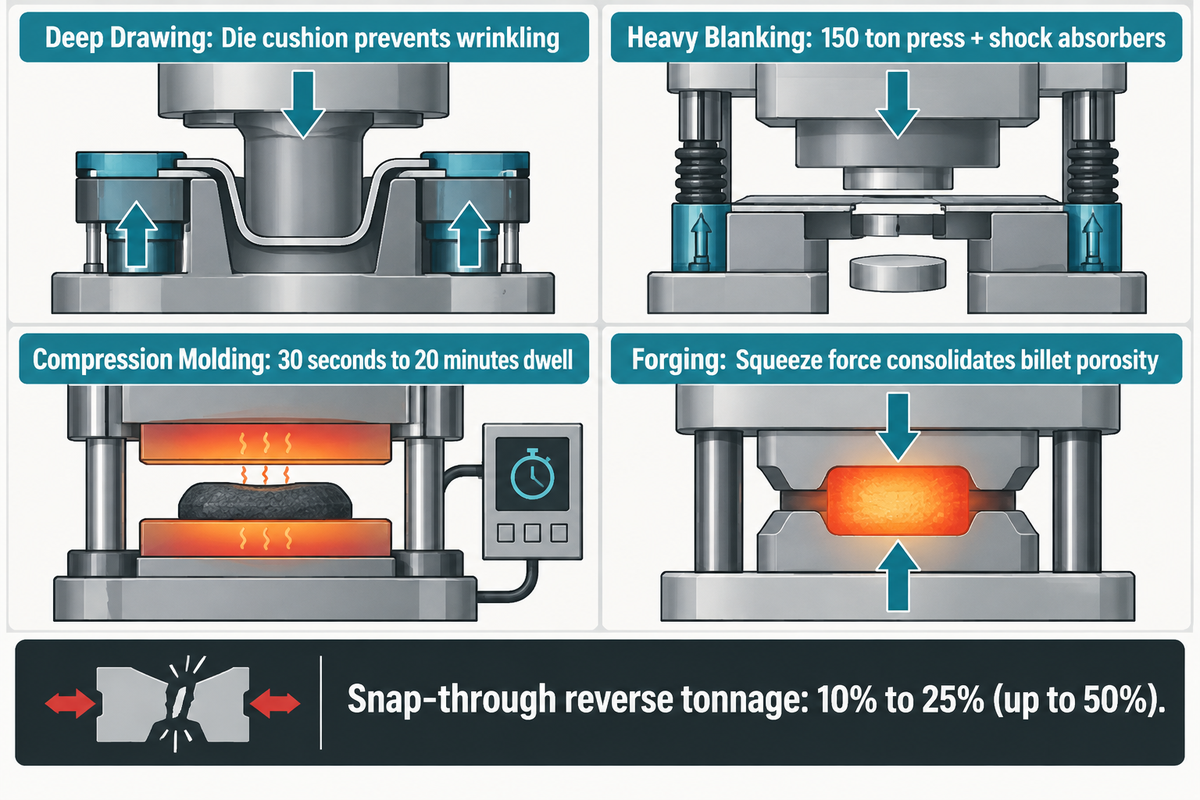
Full-stroke force control is especially advantageous in deep drawing and in composite compression molding, where hydraulic machines apply full rated tonnage from initial contact with the sheet through the bottom of the draw, while concentrating 1 to 150 tons per square foot (The Fabricator).
Unlike a drop hammer or mechanical crank press that strikes the sheet metal blank at high velocity, a hydraulic slide press slows down before contact, and thus, the metal sheet flows plastically into the die cavity without tearing. Switch to a high-speed mechanical press only when shallow stamping or blanking runs exceed 30 SPM.
Blank Holder Tonnage, Cushions, and High-Ton Hydraulic Press Forming
Hydraulic systems used in blanking and piercing operations create snap-through and reverse tonnage (10% to 25% and up to 50% of forward tonnage, respectively), which requires decompression valving, shock dampers, or operating the system below full tonnage (The Fabricator). When a punch shears through a thick steel plate, the sudden release of elastic energy accelerates the slide downward, and sends a tensile reverse load through the cylinder connections and frame tie rods.
Across industrial metalworking applications, hydraulic presses execute four primary forming regimes:
- Aluminum soda cans and pressure vessels used in deep drawing for the manufacture of automotive and appliance shells and pressure tanks, and fuel tanks, are drawn by the main ram into the die after a blank holder (hydraulic die cushion) has pressured the sheet with the main clamp and maintains control of the clamping while the main ram draws the sheet into the die without wrinkling.
- For heavy blanking, piercing, and stamping, a 150 ton hydraulic press or larger straight-side unit stamps structural brackets and agricultural equipment plates while hydraulic shock absorbers arrest breakthrough snap-through to protect the dies.
- In composites and aerospace compression molding of aircraft and SMC, automotive body panels and pressure rubber gaskets, heated platens with constant clamping force and programmable timers (from 30 seconds to 20 minutes) are used.
- In forging, the porosity of alloy steel and titanium billets is consolidated by a squeeze force where a surface hammer blow wouldn’t consolidate.
Precision Bearing Press-Fit, Bushing Assembly, and Straightening Work
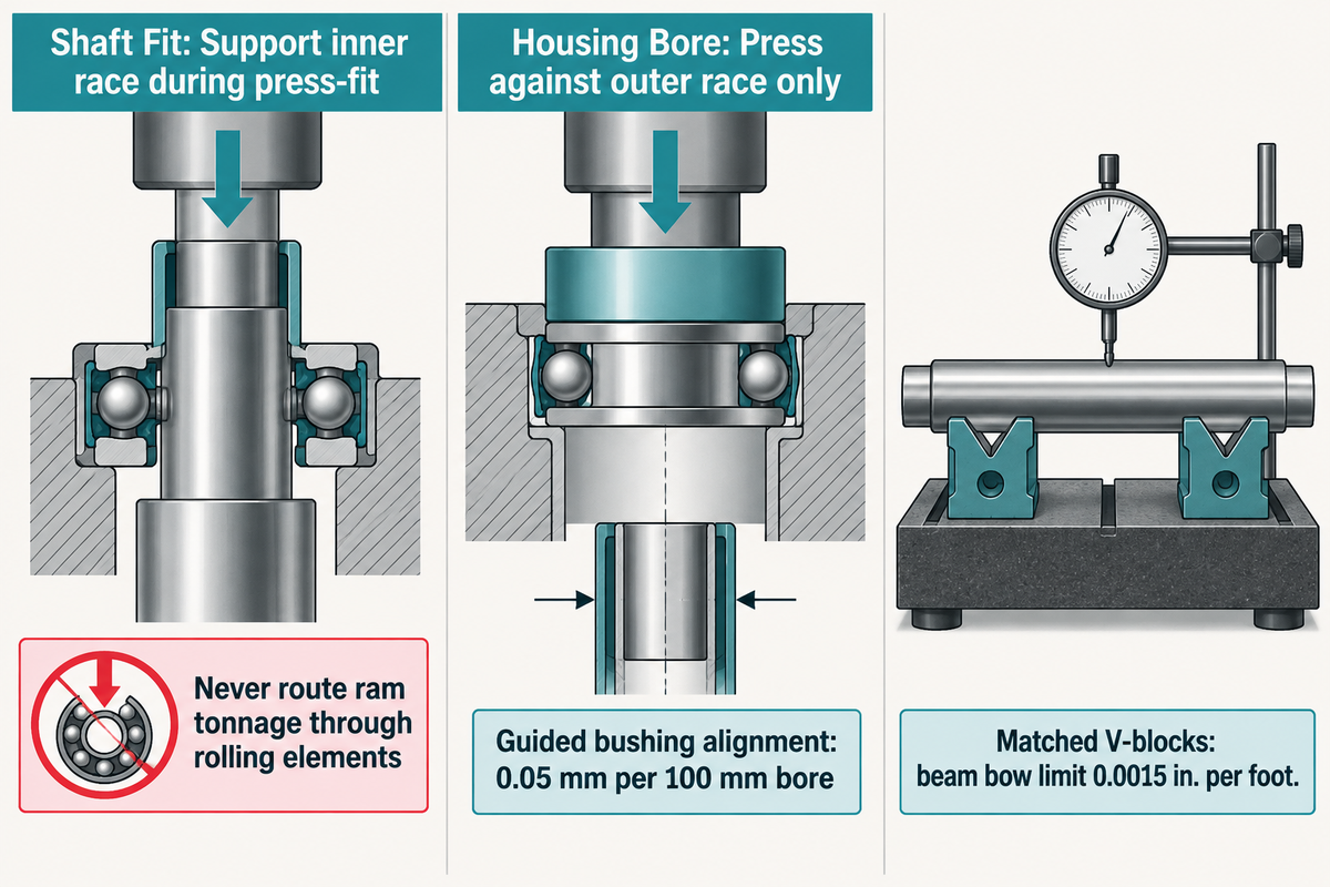
In bearing pressing and bushing assembly, apply pressing force with a ring with interference fit. Support inner race when pressing bearing onto a shaft. Press against the outer race when seating a bearing into a housing bore (Assembly Magazine).
A production press-fit station with force capacity spanning 50 N to 600 kN and automatic go/no-go verification is used for the manufacture of housing and rotor assemblies. Routing the hydraulic ram tonnage through rolling elements brinells the raceways and ruins the bearing before it’s used for service.
Arbor Plates, V-Blocks, and Shop Press Accessory Selection for Trailer and Auto Repair
In automotive repair, heavy trailer axle maintenance, and machine shop fabrication, operator tooling setup determines whether a press-fit succeeds or shatters an arbor plate. When pressing bearings, suspension bushings, or gears off a transmission shaft, support the housing directly beneath the bore wall using machined steel arbor plates or a stepped pressing sleeve. Machinists on Practical Machinist emphasize that precision bending and straightening dies limit acceptable beam bow to 0.0015 in. per foot; bridging a wide gap between bolster channels with flame-cut scrap steel or cast-iron blocks risks sudden brittle fracture under load.
Follow the four engineering rules for press-fit assembly, shaft straightening, and keyway broaching:
- Verify diametral interference before pressing: Calculate required press force using shaft-to-hub diametral interference, contact length, and friction coefficient and use interference fit engineering allowances. Consider press-fit tolerance stack-up to ensure that tight-limit parts don’t gall the bore.
- Align ram, pilot mandrel, and bolster backup: Use guided press-fit tooling and fixture alignment sleeves so the bushing enters square within 0.05 mm per 100 mm of bore depth.
- Use a similar process as before to align matched V-blocks to the centerline of the shafts. The key difference here’s to use elastic spring-back and control of the hydraulic cylinder stroke to alleviate shaft runout.
- When using a keyway broach to cut a keyway in a hub of a gear, ensure that at least two to three of the broach teeth are in the hub at all times while flooding the keyway with cutting fluid.
Sizing Capacity and Tonnage: Worked Force, PSI, and Cylinder Bore Calculation
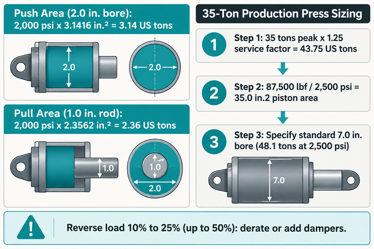
Use a hydraulic press with 1.25 service factor to account for peak calculated process force to allow the pump and relief valve to operate below maximum system PSI during continuous production. The pushing force in US tons is equal to operating pressure (PSI) times the cross-sectional area of the piston ( π × (Bore / 2)2) divided by 2,000 lbs/ton (Firgelli Automations).
If reverse tonnage reaches 10% to 25%, and up to 50% forward force, derate the press or use hydraulic shock dampers (The Fabricator).
What size hydraulic shop press do I need?
Choose a 10 to 15 ton benchtop unit for small electronics, armatures, and light bushings. A 20 to 30 ton floor unit covers passenger and automotive wheel bearings and control arm bushings. 50 to 75 tons is needed for heavy truck and trailer axles, and thick plate straightening and large shaft assembly requires a 100 to 176 ton industrial model (Scotchman Industries).
Maximum system pressure: At what PSI does the press develop full tonnage?
Industrial production hydraulic presses develop full rated tonnage between 2,000 and 3,500 psi (140 to 240 bar) for continuous multi-shift operation, whereas intermittent manual shop presses and portable cylinders run up to 8,000 to 10,000 psi. Lower continuous operating PSI extends piston seal life and reduces oil heating across the relief valve.
Ideal cylinder force calculations (F = P × A) neglect packing friction, pressure drop across directional valves, and area loss of rod-end during retraction, therefore, continuous-duty cylinder force sizing requires a service factor of 1.2 to 1.3 above the calculated tonnage (Firgelli Automations).
Worked Engineering Example: Cylinder Bore, PSI, and Continuous-Duty Sizing
1. Verified Baseline Cylinder Check (Firgelli Automations Reference): Assume a hydraulic cylinder with bore D = 2.0 in., rod diameter d = 1.0 in., and operating pressure P = 2,000 psi (Firgelli Automations):
- Extension piston area: Apush = π × (2.0 / 2)2 = 3.1416 in.2 → Push force = 2,000 psi × 3.1416 in.2 = 6,283 lbf = 3.14 US tons (27.95 kN).
- Retraction annular area: Apull = 3.1416 − π × (1.0 / 2)2 = 2.3562 in.2 → Pull force = 2,000 psi × 2.3562 in.2 = 4,712 lbf = 2.36 US tons (20.96 kN).
2. Production Press Sizing for a 35-Ton Forming & Press-Fit Job: Assumed inputs: peak process force = 35 US tons (70,000 lbf), continuous-duty service factor = 1.25, and target continuous hydraulic pressure = 2,500 psi. Required press rating = 35 tons × 1.25 = 43.75 US tons (select a standard 50-ton hydraulic press). To deliver 43.75 tons (87,500 lbf) at 2,500 psi, required piston area A = 87,500 lbf ÷ 2,500 psi = 35.0 in.2, which gives a squared radius of 35.0 / π = 11.14 in.2 (a 3.34 in. radius, or minimum cylinder bore D = 2 × 3.34 = 6.68 in.; specify a standard 7.0 in. bore cylinder, which develops 48.1 tons at 2,500 psi). This sizing calculation sets hydraulic cylinder capacity; it doesn’t replace a frame deflection check for off-center dies.
What Drives Price from a 20-Ton Shop Press to an Industrial Production Hydraulic Press?
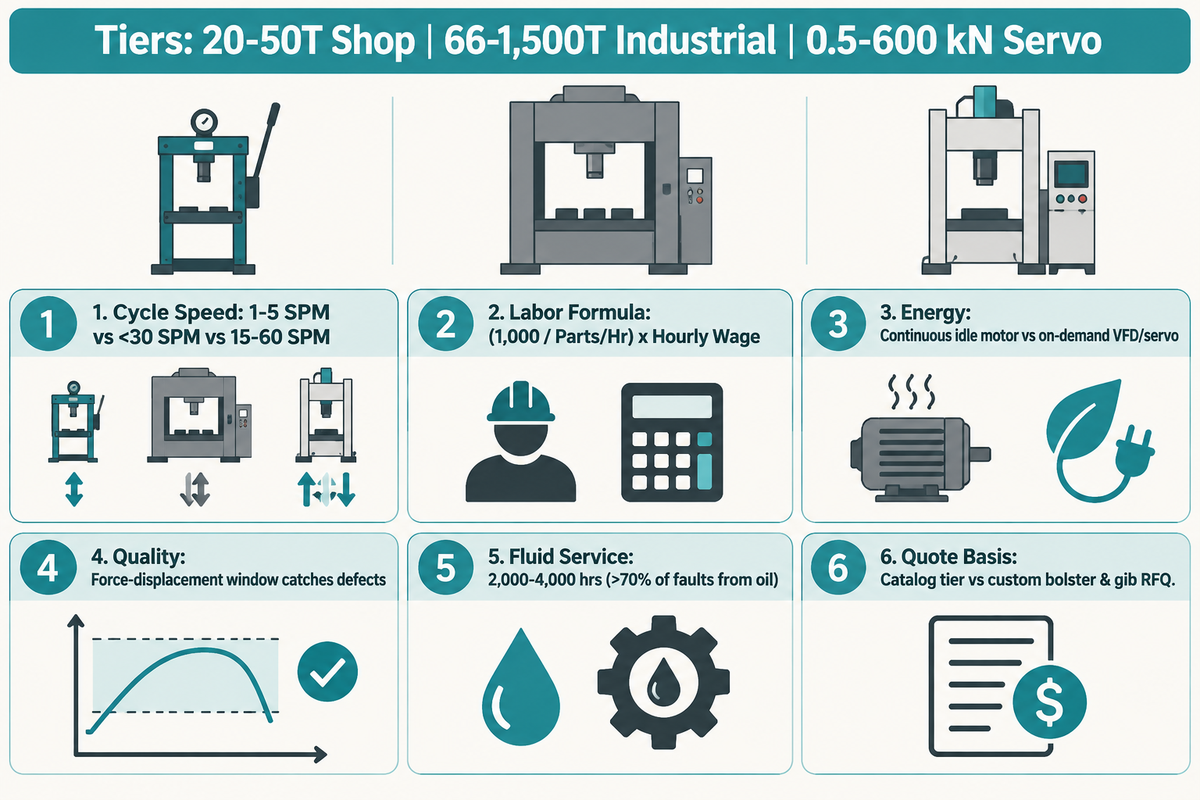
The price of an entry-level shop press 20-ton manual H-frame to an industrial 100-ton to 1,500-ton production hydraulic press differs based on the construction of the frame, the type of slide guidance, control of pump, and the level of safety integration. Buyers should request a quote for their tonnage and bolster envelope (Beckwood Press; Scotchman Industries).
Insufficient pressure of a hydraulic press leads to variations in part thickness and bend angle, increasing scrap. Long-term misuse of press increases machine downtime and maintenance costs (VIGERT; The Fabricator). Six hardware and control subsystems account for the capital and operating cost gap between a maintenance shop press and an automated production press: (1) thermal stress-relieved and CNC-planed steel frames; (2) 4-column bronze bushings or 8-point square gib ways; (3) closed-loop proportional or servo-pump manifolds; (4) kidney-loop filtration and heat exchangers; (5) ANSI B11.2 dual-channel safety PLC and light curtains; and (6) PLC ethernet integration for a loading robot and force-distance quality signature logging.
Rather than comparing upfront sticker price alone, evaluate total cost per 1,000 accepted parts using the 1,000-Accepted-Part Pressing Cost Worksheet below by plugging in your plant’s cycle time, operator labor rate, kWh tariff, and reject rate.
| Cost & Operating Parameter | Manual / Air-Hydraulic Shop Press (20–50T) | Conventional Industrial Hydraulic Press (66–1,500T) | Servo-Pump / Servo-Electric Assembly Press (0.5–600 kN) |
|---|---|---|---|
| 1. Typical Cycle Speed & Throughput | 1 to 5 SPM (manual lever or foot pump alignment) | <30 SPM (fast approach >1 m/sec + decompression dwell) (The Fabricator) | 15 to 60 SPM (programmable motion profile & robot tend) |
| 2. Direct Operator Labor Formula per 1,000 Parts | (1,000 ÷ Parts/Hr) × Hourly Wage (1 dedicated operator) | (1,000 ÷ Parts/Hr) × Hourly Wage (manual load or feeder) | (1,000 ÷ Parts/Hr) × 0.5 Shared Cell Wage (automated cell) |
| 3. Electrical Energy Consumption Profile | Intermittent shop air compressor draw (90–120 psi) | Constant-speed motor runs continuously during idle and dwell (The Fabricator) | VFD servo-pump or electric actuator draws power on demand only (The Fabricator) |
| 4. Scrap & Rework Risk Driver | Open-loop analog gauge reading; unguided ram tilt under eccentric load | Pressure-switch reversal; scrap rises if relief valve or oil overheats (VIGERT) | In-process force-displacement curve window catches defects immediately (Assembly Magazine) |
| 5. Fluid, Filter & Seal Maintenance Interval | Periodic cylinder packing & air line water-trap service | Oil & filter service every 2,000–4,000 hrs; contamination can cause over 70% of faults (VIGERT) | Oil-free sealed roller/ball screw or cooler on-demand VFD oil circuit |
| 6. Equipment Capital & Quote Basis | Standard catalog tier (varies by manual vs. air pump & bed winch) | Custom RFQ quote (varies by bolster size, gib guidance & cushion) | Custom RFQ quote (offset by lower energy, oil & scrap cost per 1,000 parts) |
Safety Guarding, Relief Valve Protection, Maintenance, and Troubleshooting
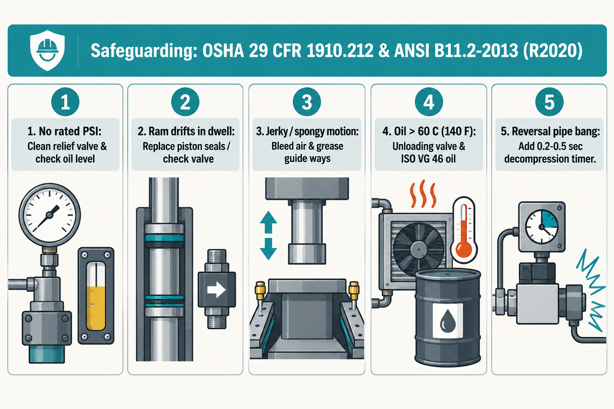
In the U.S., workplace safeguarding for hydraulic presses is governed by OSHA 29 CFR 1910.212 general machine guarding and the consensus standard ANSI B11.2-2013 (R2020), because OSHA 29 CFR 1910.217 explicitly excludes hydraulic and pneumatic power presses (OSHA Standard Interpretation 1983-10-04; U.S. Federal Register).
Because hydraulic oil contamination causes over 70% of hydraulic system failures, schedule oil and filter service every 2,000 to 4,000 operating hours or via annual oil analysis (VIGERT).
“Machine guarding to protect employees exposed to the hazards of hydraulic presses is regulated by 29 CFR 1910.212.”
Relief Valve Calibration, Reservoir Fluid Cleanliness, and OSHA/ANSI Safeguarding
Operators can be exposed to point-of-operation crushing hazards in the course of manually loading or unloading the machine (OSHA Machine Guarding eTool). A press control system that meets these safety requirements contains at least three physical safeguards: (1) an interlocked barrier guard, Type 4 presence-sensing light curtains, or an anti-tie down two-hand control; (2) mechanical slide props or a pilot-operated counterbalance valve to prevent the force of gravity from drifting the ram down during a die change; and (3) a calibrated hydraulic press relief valve.
| Observed Press Symptom | Primary Root Cause | Diagnostic Check & Corrective Action |
|---|---|---|
| 1. Ram fails to build rated PSI under load | Contaminated or miscalibrated pressure relief valve; worn hydraulic pump; low reservoir oil level | Inspect reservoir sight glass; clean relief valve poppet seat; test pump deadhead pressure against gauge |
| 2. Ram drifts downward or loses pressure during dwell | Bypassing piston packing seals inside cylinder; leaking pilot-operated check valve or prefill valve | Isolate cylinder port to check internal piston bypass; replace polyurethane/PTFE piston seals |
| 3. Jerky, spongy, or chattering ram motion | Air entrained in hydraulic circuit (pump suction leak); unlubricated gibs or tie-rod bushings | Tighten pump suction fittings; cycle cylinder to bleed trapped air at high point; grease guide ways |
| 4. Hydraulic oil overheating above 60 °C (140 °F) | Constant-speed pump dumping across relief valve during idle/dwell; fouled oil heat exchanger | Set unloading valve for idle periods; clean air/water oil cooler fins; verify ISO VG 46 oil viscosity |
| 5. Loud pipe bang at bottom of stroke or reversal | Missing decompression dwell before directional valve shift; excessive blanking snap-through | Add 0.2–0.5 sec decompression bleed timer before reversal; install blanking shock dampers |
How to Evaluate Industrial Press and Precision Assembly System Suppliers
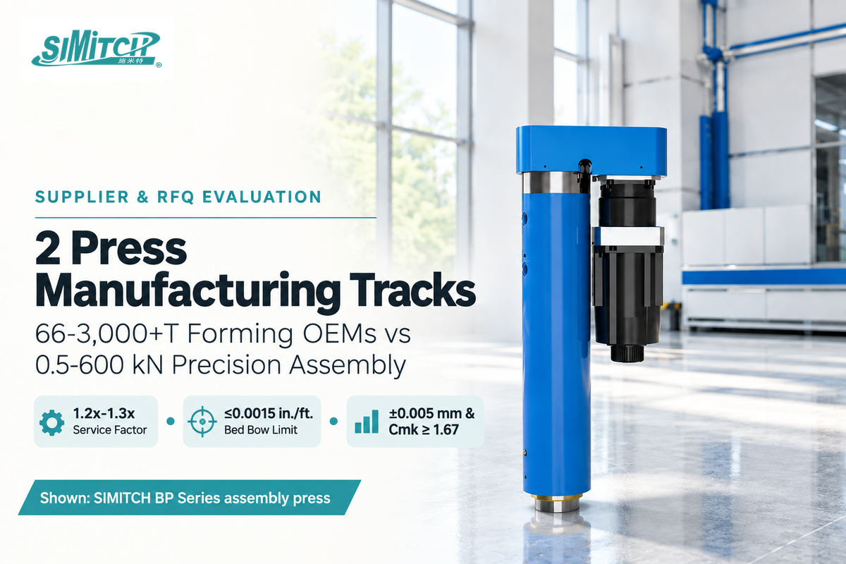
Break down your press suppliers into two manufacturing tracks before issuing a request for quote (RFQ): heavy metal-forming hydraulic press OEMs (e.g. Schuler, Beckwood Press, Scotchman Industries, etc.) build 66-to-3,000+ ton machines for sheet metal drawing, while precision assembly specialists (e.g. Kistler, Janome, Promess and SIMITCH) design servo-electric and pneumohydraulic station (Beckwood Press; Assembly Magazine).
Sending a micro-tolerance bearing assembly RFQ to a heavy stamping press builder results in oversized, unmonitored equipment. Within the precision assembly track, SIMITCH designs and manufactures precision servo press systems (including the C-frame anti-deflection BP Bending Type precision assembly press series), hydro-pneumatic drive cylinders, sheet metal clinching machines, and self-piercing riveting equipment for automotive and industrial assembly lines. When your process requires closed-loop force-displacement window monitoring, ANSI B11.2-2013 (R2020) safeguarding (with a revision expected in 2026 per B11 Standards Inc.), and repeatable part traceability, copy the 8-parameter RFQ specification benchmark table below into your supplier inquiry.
RFQ checklist: copy these 8 technical parameters into your press quote request:
| Parameter & Specification | Recommended Benchmark Range | Why It Matters in Production | Verification Reference & Standard |
|---|---|---|---|
| 1. Continuous & Peak Force Rating | Size press with a 1.2x to 1.3x service factor above peak force (e.g., 50T rating for 35T peak load) | Prevents relief valve overheating and seal blow-by during continuous shifts | Supplier hydraulic bore/PSI chart (Firgelli) |
| 2. Bed Length Coverage & Off-Center Load | Tooling footprint covering at least 66% of bed length for full rated tonnage | Concentrated dies on one-third of bed can cut usable capacity to 50% | OEM off-center derating curve (The Fabricator) |
| 3. Platen Parallelism & Deflection Limit | ≤0.0015 in./ft. bed-to-ram bow under rated load for precision forming and press-fitting | Controls punch-to-die clearance and prevents bushing or bearing cocking | Dial indicator deflection test at FAT (Practical Machinist) |
| 4. Reverse Tonnage & Decompression Control | Decompression bleed timer (0.1–0.5 s) + shock dampers when reverse load can reach 10% to 25% and up to 50% | Eliminates snap-through structural fatigue and directional valve water hammer | Pressure trace readout during breakthrough (The Fabricator) |
| 5. Force-Displacement Signature Monitoring | ±0.005 mm position repeatability + load cell curve window for precision assembly (0.5–600 kN) | Detects undersized bores, galled shafts, or missing bearings in real time | Sample 30-piece capability run (Cmk ≥ 1.67) (Assembly Magazine) |
| 6. Cylinder Bore, Rod & Working Pressure | 2,000–3,500 psi continuous industrial rating; verify rod annular area subtraction on return stroke | Ensures sufficient stripping and retraction force when pulling punches out of deep dies | Cylinder push/pull calculation sheet (Firgelli) |
| 7. Drive Energy & Cycle Rate Target | <30 SPM for full hydraulic deep drawing; 15–60 SPM with VFD servo-pump or servo-electric drive | Eliminates idle motor power draw and matches cycle time to automated workcell tact | Cycle time & kWh draw test (The Fabricator) |
| 8. Safety & Fluid Maintenance Compliance | OSHA 29 CFR 1910.212 / ANSI B11.2-2013 (R2020) safeguarding; 2,000–4,000 hr oil service life | Protects operator hands and prevents contamination that can cause over 70% of hydraulic faults | Dual-channel safety schematic & oil filtration spec (Federal Register; VIGERT) |
What Is Changing in Electro-Hydraulic and Servo-Assisted Press Technology?
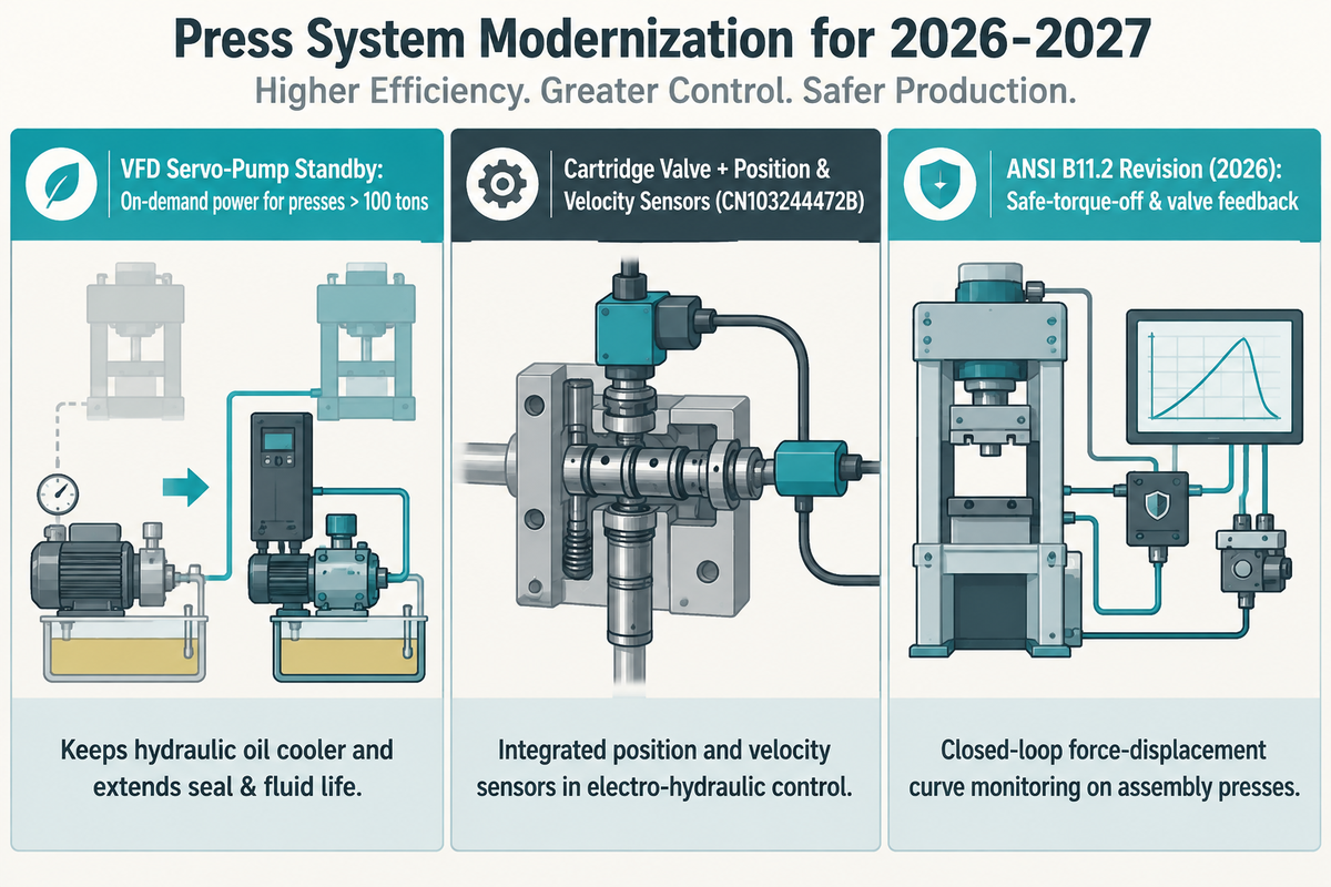
Plant energy budgets and part-level quality audits are the main drivers encouraging press buyers to transition away from constant-speed hydraulic power units to VFD servo-pump hydraulics and closed-loop servo-presses (The Fabricator).
From a power-usage perspective, constant-speed electric motors spinning a hydraulic pump continuously during idle loading and dwell periods consume more energy than VFD and servo-pump drives which draw power only during active ram motion, thereby keeping hydraulic oil cooler and extending seal and fluid life.
At the cylinder control level, integrated cartridge directional valves, along with integrated position and velocity sensors, are gaining traction in electro-hydraulic architectures, disclosed in a granted servo-hydraulic cylinder control patent CN103244472B. Simultaneously, B11 Standards Inc. is revising the ANSI B11.2 safety standard for hydraulic and pneumatic power presses (with expected publication in 2026), focusing on integrated safe-torque-off and monitored valve feedback for automated press cells (B11 Standards Inc.). For 2026-2027 production lines, request on-demand servo-pump control standby for hydraulic presses > 100 tons and demand force-displacement curve monitoring on assembly presses < 60 tons.
Frequently Asked Questions
Q: What is a hydraulic press used for in manufacturing and automotive repair?
A hydraulic press is used for deep drawing, metal stamping, blanking, compression molding, forging, shaft straightening, and interference press-fitting of bearings, bushings and gears.
Industrial manufacturing plants need 100-3,000 ton hydraulic presses for sheet metal forming, while auto repair shops use 20 ton floor presses for wheel bearings and suspension bushings.
Q: What is the difference between a hydraulic press and a mechanical power press?
A hydraulic press is able to deliver its rated tonnage throughout the entire ram stroke, whereas a mechanical flywheel press can do the same only at bottom dead center.
Hydraulic presses suit deep drawing and dwell-time molding below 30 SPM, while mechanical presses handle high-speed blanking from 40 to 600+ strokes per minute.
Q: What is the difference between a manual and an electric hydraulic press?
A manual hydraulic press uses a hand-lever pump to build cylinder pressure for infrequent maintenance, and an electric hydraulic press uses a motorized pump for continuous repeatable cycles.
Electric hydraulic units add solenoid or proportional valves, pressure switches, and dwell timers that eliminate operator pumping fatigue in multi-shift production cells.
Q: Does a hydraulic press use water or hydraulic oil?
Shop hydraulic presses and industrial units use anti-wear hydraulic oil (typically ISO VG 32 or VG 46) as opposed to water.
Pump pistons are lubricated by hydraulic oil for 2,000-4,000 operating hours.
Q: Why is hydraulic press pressure low under load, and how does the relief valve work?
Misadjustment or contamination of the relief valve can cause a hydraulic press to lose pressure under load. Other factors can include a worn pump, hydraulic seal failure, or low oil in the reservoir.
The relief valve on a press serves as a spring-loaded limit switch and opens a return path to the reservoir, preventing cylinder overload. If the relief valve is held open by debris, oil dumps back to the reservoir and the ram stalls prior to reaching its target tonnage.
Q: Are hydraulic presses dangerous without guarding and rated bolster plates?
Hydraulic presses definitely have the potential for unguarded amputation, pinch-point, high-pressure fluid injection, and projectile hazards.
Per OSHA 29 CFR 1910.212 and ANSI B11.2, point-of-operation guarding, rated bolster and arbor plates, and mechanical slide locks are required during maintenance for these pieces of equipment.
Q: Can a hydraulic press crush anything, and how do viral crushing videos differ from industrial forming?
No. A hydraulic press can’t crush materials whose yield strength exceeds the contact stress of the tooling and hardened steel dies will dent or shatter if overloaded.
Finnish machinist Lauri Vuohensilta started the Hydraulic Press Channel to film extreme compression tests behind thick polycarbonate blast shields. Those demonstrations use a 150 ton hydraulic press to crush hardened steel bearings, bowling balls, and stacks of soda cans until brittle fracture occurs. Industrial metal forming instead uses matched dies, calibrated relief valves, and controlled dwell to shape workpieces without tool failure.
Need a Precision Press-Fit, Hydro-Pneumatic, or Servo Assembly Solution?
If your production line requires repeatable bearing and bushing press-fitting, closed-loop force-displacement monitoring, pneumohydraulic drive cylinders, or sheet metal clinching without hydraulic oil leaks, our engineers can help you size the exact force window and frame stiffness for your workpiece.
Why We Wrote This Engineering Guide
We created this hydraulic press engineering guide because clients often compare open-loop hydraulic shop presses to hydro-pneumatic cylinders and closed-loop servo presses to determine which offer the greatest peak tonnage. The 5-stage circuit table, 9-row frame selection matrix, and 1,000-accepted-part cost worksheet draw directly from OSHA 29 CFR 1910.212, ANSI B11.2-2013 (R2020), and verified press engineering literature. Edited by the Suzhou Simitch Machinery Co., Ltd. technical staff.
References & Sources
- Machine Guarding eTool: Hydraulic Presses Occupational Safety and Health Administration (OSHA)
- Standard Interpretation: Applicability of 29 CFR 1910.212 to Hydraulic Power Presses (1983-10-04) Occupational Safety and Health Administration (OSHA)
- Pascal’s Principle, Introductory Physics for the Health and Life Sciences I Michigan State University Libraries
- Hydraulic Press: Engineering & Fluid Mechanics Encyclopaedia Britannica
- Mechanical Power Presses Update and ANSI B11.2-2013 (R2020) Consensus Standard Reference (2021-15995) U.S. Federal Register
- ANSI B11.2 Scope: Hydraulic and Pneumatic Power Presses Safety Requirements B11 Standards, Inc.
- Stamping 101: How Does a Hydraulic Press Work? The Fabricator (FMA)
- 5 Considerations When Replacing a Hydraulic Press With a Servo Press The Fabricator (FMA)
- Understanding Press Tonnage: Capacity, Off-Center Loads, and Reverse Tonnage The Fabricator (Dr. David Diaz-Infante)
- Hydraulic Press Technology Trends That Boost Energy Efficiency and Usability The Fabricator (FMA)
- Assembly Presses for Low-Force Applications Assembly Magazine
- Choosing the Best Features for Your Custom Hydraulic Press Beckwood Press
- PressPro Industrial Hydraulic Shop Presses (66, 110, and 176 Ton Specifications) Scotchman Industries
- Hydraulic Press Force Calculator: Tonnage From Cylinder Bore and PSI Firgelli Automations
- Common Hydraulic Press Problems and How to Fix Them VIGERT
- Patent CN103244472B: Servo Hydraulic Cylinder Valve System Google Patents