Get in touch with Suzhou Simitch Machinery Co., Ltd Company

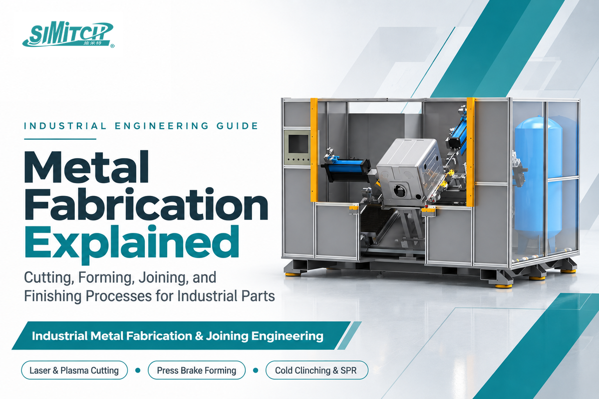
Updated November 2026 | Industrial Metal Fabrication & Joining Engineering Guide
Metal fabrication is the process of taking sheet metal, structural plates, and rolled profiles, and turning them into finished industrial parts (Southern Metal Fabricators). Rather than using one machine tool, a metal fabricator routes stock through five processes: design, cutting, forming, joining, and finishing (NAMF).
Getting the wrong cutting, bending, or joining sequence leads to increases in scrap and tooling rework across a metal fabrication project. Edges of oxygen-cut carbon steel may crack during tight press-brake forming. Spot welding galvanized steel also burns off protective zinc coatings (TWI). This 2026 guide provides process selection matrices, press-brake die formulas, thermal-versus-cold joining rules, and ISO 2768 tolerance comparisons for engineering teams.
Direct Answer: Metal fabrication transforms flat sheet, plate, and structural sections into finished metal components through cutting, bending, and assembly (Southern Metal Fabricators). Fiber laser cutting and air bending suit sheet-metal fabrication. Specifically, V = 8t is a die-opening rule of thumb for cold-rolled mild steel up to 0.5 inch thick, and ISO 2768-mK tolerances apply when specified on the drawing. Cold mechanical clinching and self-piercing riveting join galvanized, pre-painted and aluminum sheets without welding heat, if the sheets are ductile enough to allow for a mechanical interlock.
Quick Specs: Metal Fabrication Engineering Benchmarks
| Core Production Workflow | 5 sequential stages: CAD design, cutting, forming, joining, and finishing across 3 project phases (NAMF; Southern Metal Fabricators) |
| Cutting Thickness Crossover | Fiber laser for thin sheet; plasma offers speed and cost advantages above 16 mm (5/8 in.) on conductive plate; waterjet cuts across thin sheet to thick plate without heat (Hypertherm) |
| Press Brake Air-Bending Rule | For air bending cold-rolled mild steel up to 0.5 in. thick, V = 8t is a die-opening rule of thumb, and the resulting inside bend radius is approximately 0.16 × V (The Fabricator) |
| Cold Joining & Servo Pressing | Clinching and SPR for coated/aluminum stacks; servo presses span 0.5 to 400+ kN at 50–200 mm/s approach and 1,000 Hz sampling (TWI; AMD Machines) |
| Tolerances, Coating & Safety | ISO 2768-mK tolerances apply when specified on the drawing; powder coat adds ~0.002 in. per coated surface; ASTM A123/A123M hot-dip galvanizing; OSHA 29 CFR 1910.212 guarding (GD Prototyping; Approved Sheet Metal; AGA; OSHA) |
Key Engineering Takeaways.
- Route parts according to stock geometry. Flat-pattern enclosures should be made using sheet metal fabrication, and solid 3D pockets should be machined using a subtractive CNC process.
- Design bends around standard shop V-dies. In air bending of cold rolled mild steel, up to 0.5” thick, the opening of the V-die (V = 8t) governs the natural radius on the inside (The Fabricator).
- Clinching and self-piercing riveting provide cold joining alternatives for galvanized steel and aluminum, avoiding zinc burn-off and welding-induced thermal warpage (Assembly Magazine). They can replace selected spot welded joints when punch-and-die access, sheet ductility, stack order and required joint performance support the process.
- Clearances for coated holes must account for coating thickness. Electrostatic powder coating increases material thickness by approximately 0.002” on each side, increasing the overall dimension by 0.004” (Approved Sheet Metal).
What Is Metal Fabrication and How Does It Differ from Machining or Welding?
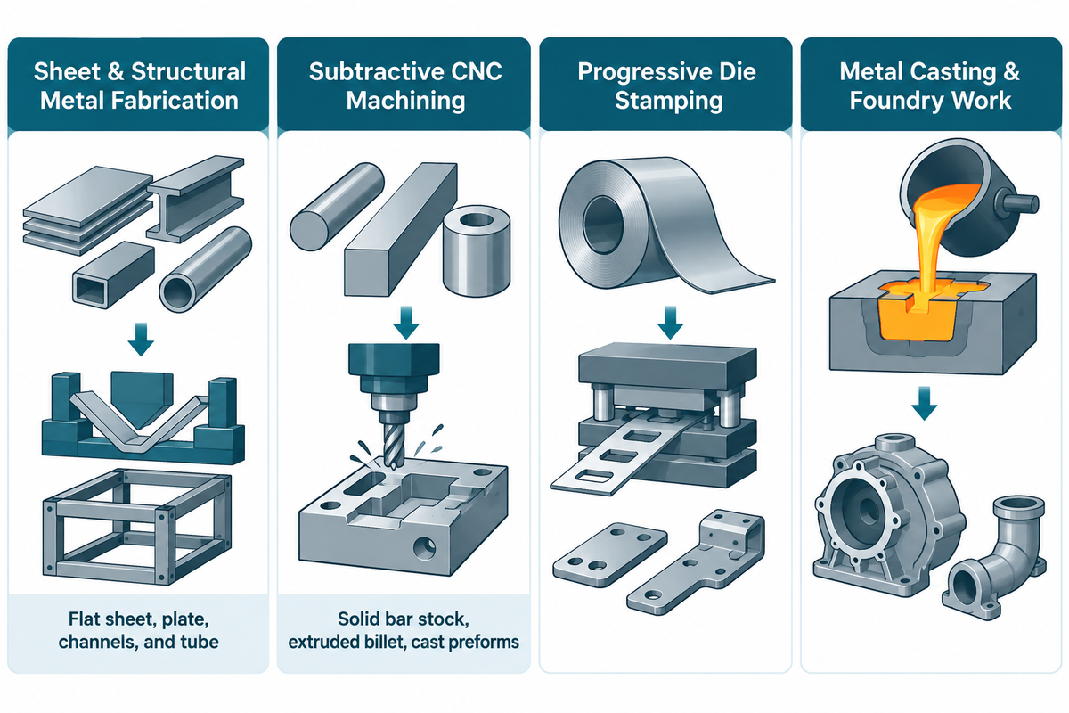
Metal fabrication is the value-added manufacturing process of creating a product or structure from raw metal by cutting, bending, and assembly (Southern Metal Fabricators). Instead of carving a solid block on one milling center, a fabricator transforms flat sheet, plate, tube, and bar stock into parts and assemblies.
A full-service fabrication process frequently accompanies associated metalworking processes, such as casting, powder coating, powder metallurgy, machining and welding (TWI). The majority of industrial projects may be sub-divided into three phases: shop drawing design, shop-floor fabrication, and final installation (Southern Metal Fabricators). Evaluating expert metal fabrication services early prevents routing a hollow sheet-metal housing to a solid-billet CNC machine shop.
| Manufacturing Discipline | Primary Raw Stock | Core Operations | Standard Tolerance Class | Best-Fit Production Volume |
|---|---|---|---|---|
| Sheet & Structural Metal Fabrication | Flat sheet, plate, structural channels, and tube | Laser/plasma cutting, press brake bending, welding, clinching, SPR | Drawing-specified general tolerances, such as ISO 2768-mK where selected (GD Prototyping) | Prototypes to medium-volume runs (1 to 10,000+ units) with flexible tooling |
| Subtractive CNC Machining | Solid bar stock, extruded billet, cast preforms | 3-axis to 5-axis milling, CNC turning, precision boring, grinding | Drawing-specified fine linear tolerances and feature GD&T callouts | Low-to-medium volume precision blocks, shafts, and bearing housings |
| Progressive Die Stamping | Continuous coiled sheet metal strip | Multi-station punching, coining, drawing, and blanking in dedicated dies | High station-to-station repeatability governed by dedicated hard tooling | High-volume mass production where die amortization is justified |
| Metal Casting & Foundry Work | Molten iron, steel, aluminum, or zinc ingots | Sand casting, die casting, investment casting, secondary face milling | Casting-specific dimensional tolerances for as-cast features; dimensional and geometric drawing tolerances for machined mating features | Complex internal geometries, pump housings, and heavy machine bases |
What Is the Difference Between Welding and Metal Fabrication?
Metal fabrication is the complete production workflow that transforms raw stock into a finished assembly ( Southern Metal Fabricators). Welding is a thermal joining process used in the assembly step. Fabricators sequence cutting, forming and joining around part geometry and tool access; some assemblies need no bending, while others are joined before final forming.
During assembly, the fabricator selects the joining method that matches the alloy and coating. Welding and fabrication teams employ fusion weld processes, threaded fasteners and cold mechanical joining (TWI ). Put differently, welding and custom assembly encompass joining processes, while custom fabrication covers the entire manufacturing process.
How Does a Metal Fabrication Project Move from CAD Nesting to Final Inspection?
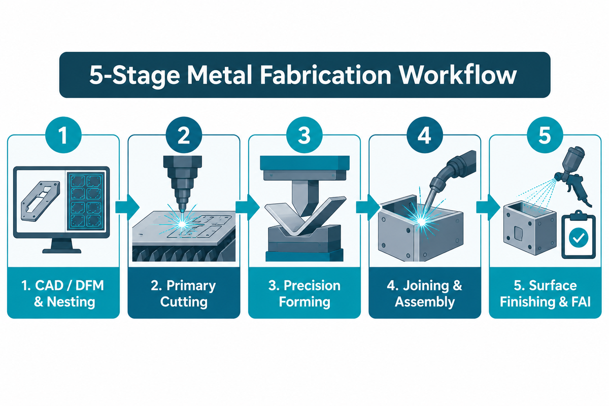
An industrial metal fabrication project goes through five core stages: design, cutting, forming, joining and finishing (NAMF). Each stage sets up the dimensional datum for the next operation. A simple, flat bracket may skip forming, whereas a multi-bay control cabinet requires all five stages plus finishing and first-article inspection (NAMF).
Handoff errors between engineering CAD models and shop-floor tooling often delay turnaround times. During CAD unfolding, the K-factor defines the ratio of the inner neutral axis to the thickness of the material (Protolabs). Unfolding a DXF with a generic K-factor that conflicts with shop V-die tooling leads to flange length misses in exact specifications.
In-house cutting, bending, welding, machining, powder coating, and assembly simplify scheduling and maintain control over quality (Newburgh Metals). In addition, ISO 9001:2015 or aerospace AS9100D quality management certification and documented DFM support provide a reliable supplier evaluation baseline (Fabcon).
| Production Stage | Engineering Input | Primary Shop Equipment | In-Process Quality Verification Gate |
|---|---|---|---|
| 1. CAD / DFM & Nesting | 3D STEP model + 2D tolerance drawing | CAD/CAM unfolding & sheet nesting software | Verify K-factor neutral axis ratio, bend relief width and depth, and rolling grain orientation (Protolabs) |
| 2. Primary Cutting | Nested CNC G-code program | Fiber laser, CNC turret punch, plasma, waterjet, or shear | Check flat-pattern profile dimensional accuracy, kerf taper, and edge dross removal |
| 3. Precision Forming | Press brake bend sequence & V-die setup sheet | CNC press brake, roll former, hydraulic or servo press | First-piece bend angle check and flange setback verification against specified drawing tolerances |
| 4. Joining & Assembly | Weldment or mechanical fastening sub-assembly print | MIG/TIG welders, spot welders, clinching machines, SPR cells | Weld visual inspection or closed-loop force-displacement signature sampling at 1,000 Hz+ (AMD Machines) |
| 5. Surface Finishing & FAI | Coating specification, masking map & inspection report | Powder-coating booth, hot-dip galvanizing kettle, optical scanner | Coating thickness measurement and thread plug gauge inspection; Approved Sheet Metal gives a powder-coating allowance of 0.002–0.006 in. per coated surface, while ASTM A123/A123M specifies hot-dip galvanized coatings on iron and steel products |
Which Metal Cutting Process Fits Your Material Thickness and Edge Tolerance?
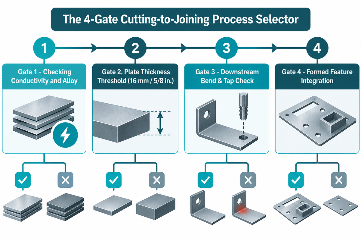
Choosing an industrial metal cutting process requires matching material conductivity, plate thickness, edge quality, and operating cost (Hypertherm). Fiber laser cutting suits thin-to-medium sheet metal requiring tight tolerances. High-definition plasma offers speed and operating-cost advantages on conductive plate thicker than 16 mm (5/8 in.) (Hypertherm).
Material chemistry first narrows your cutting options. Conventional oxyfuel cutting suits carbon steel and some low-alloy steels because it relies on exothermic iron oxidation, whereas plasma cutting requires electrically conductive metals (Hypertherm). Eliminate plasma for non-conductive composite laminates (Hypertherm). Abrasive waterjet and industrial laser systems cut both ferrous and non-ferrous materials across thin sheet and thick plate (Hypertherm). Mechanical shearing, turret punching, and band saws with hardened blades handle unheated mechanical cutting within machine tonnage limits (TWI).
| Cutting Process | Material Compatibility | Primary Thickness Zone | Thermal Edge & HAZ Effect | Ideal Fabrication Use Case |
|---|---|---|---|---|
| Fiber Laser Cutting | Carbon steel, stainless, aluminum, copper, brass | Thin sheet to medium plate (most economical ≤16 mm) | Narrow HAZ; nitrogen assist yields oxide-free edges for painting | Intricate sheet metal components and tight internal cutouts (Hypertherm) |
| High-Definition Plasma | Electrically conductive metals only (steel, stainless, aluminum) | Mid-range to thick plate; faster and lower cost above 16 mm (5/8 in.) | Wider thermal HAZ and slight bevel; handles reflective or rusty plate | Structural baseplates, bevel preparation, and bolt-ready holes (Hypertherm) |
| Abrasive Waterjet | All metals (titanium, Inconel, aluminum, tool steel) and composites | Full thickness spectrum from thin sheet to heavy slab | Zero heat-affected zone (cold erosion); zero edge hardening | Heat-sensitive aerospace alloys and thick plates needing secondary tapping (Hypertherm) |
| Oxyfuel Torch Cutting | Carbon and low-alloy steel only (cannot cut stainless or aluminum) | Very thick carbon steel plate and heavy structural sections | Thermal heat-affected zone; slag and interfering oxide require removal before welding, with grinding used for rough or defective cut edges | Heavy structural steel gussets, bridge plates, and thick counterweights (Hypertherm) |
| Mechanical Shearing & Punching | Cold-rolled steel, galvanized sheet, aluminum, 304 stainless | Thin sheet metal stock within press tonnage and die-clearance limits | Zero thermal HAZ; localized cold work-hardening along shear rollover | High-speed hole grids, louvers, embossments, and straight rectangular blanks (TWI) |
The 4-Gate Cutting-to-Joining Process Selector
Use the precision engineering sequence to prevent bending cracks and coating failures due to upstream cutting choices:
- Gate 1 – Checking Conductivity and Alloy: For aluminum and stainless steels, oxyfuel cutting is eliminated, and for non-conductive composite laminates, plasma cutting is eliminated (Hypertherm).
- Gate 2, Plate Thickness Threshold (16 mm / 5/8 in.): Route intricate sheets up to 16 mm to fiber laser. Consider high-definition plasma above 16 mm when cut quality and tolerances satisfy part requirements (Hypertherm).
- Gate 3 — Downstream Bend & Tap Check: Abrasive waterjet avoids a thermal heat-affected zone at critical bend edges or tapped holes; nitrogen-assisted laser cutting limits oxidation but can still leave a heat-affected zone and hardened edges in hardenable steels.
- Gate 4 – Formed Feature Integration: If a sheet panel requires repeating ventilation holes plus shallow louvers or countersinks, combine CNC turret punching with laser contour cutting.
When Does Turret Punching Beat Fiber Laser Cutting on Sheet Metal?
CNC turret punching is faster than fiber laser cutting when a sheet panel within the press tonnage capacity contains dense repeating hole grids, louvers or stamped ribs. A turret press punches each hole in one stroke and forms shallow 3D features directly on the machine bed.
How Do Metal Forming, Press Brake Bending, and Stamping Control Springback?
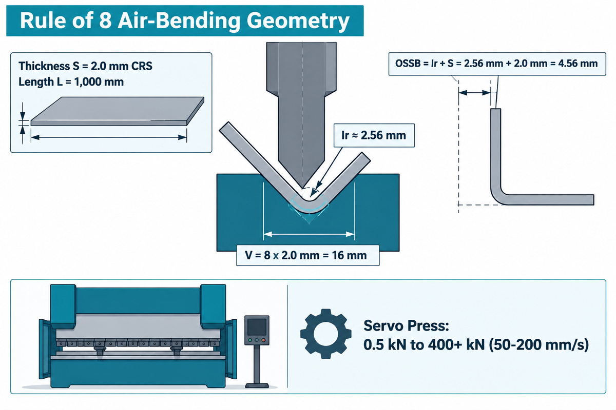
A press brake “bends” a workpiece into a V-shape die (below the die wall). The guideline set by The Fabricator is that for cold-rolled mild steel workpieces 0.5 inches or less in thickness, the die opening would be approximately eight times the thickness. Operators “overshoot” the bend slightly to compensate for springback. (Atlas Manufacturing)
A common error in CAD design is assuming that the nose radius of the punch in air bending determines the part’s inside radius. For air bending, the inside bend radius is governed by the width of the opening in the V-die, which for cold-rolled mild steel is approximately 16% of the V-opening (The Fabricator; Practical Machinist). High-precision press brake tools are ground to within +-0.0004 inch, and thus, a small adjustment is often not required to obtain the desired bend radius (The Fabricator). Because many press brake tools follow metric standards, a nominal 0.250-in. V-die opening is actually 6 mm, or 0.236 in. (The Fabricator).
For cold-rolled mild steel up to 12.7 mm (0.5 in.) thick, starting estimates for air bending are V = 8t and Ir ≈ 0.16 × V. For higher-strength steels and less ductile aluminum tempers, larger inside bend radii and wider die openings are often needed. Deep-drawn cups and similarly complex stamped shells may require forming presses with sufficient tooling, stroke, and force capacity, as well as blank-holder control, such as industrial hydraulic press tonnage and frame architectures. Precision servo assembly presses may perform press-fitting and other similar operations.
“In a perfect world, you should be able to select the V-die opening using what we call the rule of 8; that is, the V-die opening should be 8 times the material thickness.”
| Forming Parameter / Equipment Tier | Formula / Capacity Specification | Shop-Floor Engineering Application |
|---|---|---|
| Worked Air-Bending Input | Thickness S = 2.0 mm CRS mild steel; Bend length L = 1,000 mm | Standard 14-gauge enclosure panel flange formed on a CNC press brake |
| V-Die Selection (Rule of 8) | V = 8 × 2.0 mm = 16 mm die opening; natural inside radius Ir ≈ 2.56 mm | Prevents outer-fiber cracking and maintains consistent springback angle (The Fabricator) |
| Outside Setback (90° Flange) | OSSB = Ir + S = 2.56 mm + 2.0 mm = 4.56 mm | On a 90-degree flange, outside setback equals outside radius (bend radius plus thickness per Protolabs) |
| Precision Servo Assembly Press | Servo assembly presses span 0.5 kN to 400+ kN, with typical approach speeds of 50–200 mm/s and insertion speeds as low as 0.5 mm/s for delicate press-fits | Closed-loop forming, staking, and bearing insertion with 1,000 Hz+ curve sampling (AMD Machines) |
Welding vs. Cold Mechanical Joining: When Should Fabricators Use Clinching or Self-Piercing Rivets?
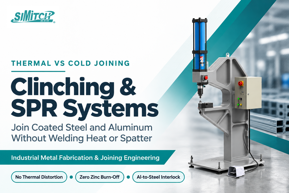
Mechanical clinching and self-piercing riveting (SPR) are cold sheet-metal joining processes (TWI). They’re good options for joints on coated steels, aluminum alloys, and dissimilar metal combinations (TWI). Since no thermal fusion takes place, there’s no heat affected zone or spatter. Additionally, no fusion means zinc fumes from welding are eliminated.
To reduce vehicle weight and boost fuel efficiency, automakers use lightweight aluminum alloys for doors, hoods, trunk lids, and body assemblies (Assembly Magazine). This material shift has led manufacturers to adopt alternatives to traditional resistance spot welding process and electrode pressure limits, including spot clinching and self-piercing rivets (Assembly Magazine). In self-piercing riveting, a punch drives a semi-tubular rivet to pierce the top sheet and flare into the lower sheet within a die (U.S. Patent US9015920B2). U.S. Patent Publication US20230041416A1 describes mechanically joining sheet stacks containing advanced high-strength steel using variable clamp force and heating to a suitable joining temperature.
Clinching and SPR systems equipped with force-displacement monitoring can record each joining cycle for process deviations. Because in-process curve or button-thickness checks can’t measure internal joint geometry directly, sectioned samples are used during tooling qualification to verify clinched-joint neck thickness and interlock. Production lines deploying self-piercing riveting (SPR) machines and servo riveting assembly systems pair in-process force monitoring with periodic destructive peel testing.
| Joining Method | Coated & Pre-Painted Stock | Dissimilar Al-to-Steel Capability | Consumables & Thermal Input | Primary Production Application |
|---|---|---|---|---|
| MIG / TIG Fusion Welding | Burns off zinc and paint; requires pre-grinding and post-weld touch-up | Not suitable (forms brittle intermetallic compounds under fusion heat) | Filler wire + shielding gas; high heat input causes sheet distortion | Structural frames, pressure vessels, and hermetically sealed seam welds (TWI) |
| Resistance Spot Welding (RSW) | Vaporizes zinc coating at weld nugget; accelerates copper electrode wear | Limited; oxide films and melting-point mismatch degrade joint strength | No filler wire; high electrical current draw and water-cooled electrodes | Bare mild steel brackets, cabinets, and conventional steel body-in-white (Assembly Magazine) |
| Mechanical Clinching | Avoids thermal coating burn-off; local plastic deformation can disrupt coatings at the interlock button | Excellent for ductile aluminum-to-steel and copper-to-steel sheet stacks | Zero fasteners or consumables; cold punch-and-die forming stroke | Galvanized ductwork, white-goods appliance panels, and automotive heat shields (Böllhoff; TWI) |
| Self-Piercing Riveting (SPR) | Requires no pre-punched hole and avoids thermal coating damage; rivet penetration and sheet deformation can disrupt coatings locally | Industry benchmark for joining aluminum castings/sheet to high-strength steel | Uses engineered semi-tubular rivets fed automatically to the nosepiece | EV battery enclosures, automotive hoods/doors, and structural aluminum frames (Assembly Magazine; US9015920B2) |
Why Do HVAC Ducts, Appliance Panels, and EV Battery Enclosures Use Clinching and SPR Instead of Spot Welding?
HVAC contractors and appliance manufacturers use cold joining for ductwork and washing-machine cabinets made from hot-dip galvanized or pre-painted coil stock because spot welding burns away the zinc layer and leaves black soot marks. Specifying clinching machines for HVAC ducts and appliance panels forms mechanical interlocks directly from the parent sheets without added fasteners (Böllhoff). HVAC duct and appliance-panel seams may still need sealant for leak tightness, and tooling wear remains an operating cost. In EV battery trays and lightweight closures where aluminum must join to steel, self-piercing riveting forms a mechanical joint without welding-induced thermal distortion (TWI). Suitable sheet ductility, stack order, and rivet-and-die geometry enable a sound interlock.
Which Metals Are Most Commonly Used in Industrial Fabrication and What Are Their Limits?
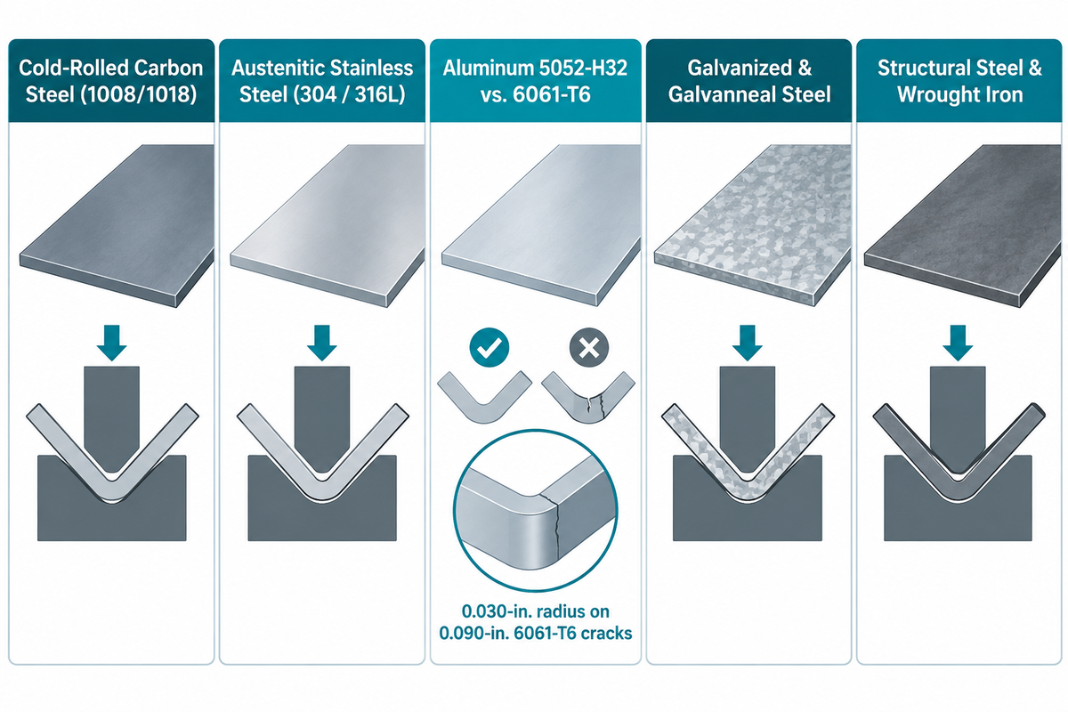
Common fabrication materials include cold-rolled carbon steel, 304 and 316L stainless steel, galvanneal or galvanized steel, and aluminum alloys. Specifying sheet thickness in millimeters or inches, as opposed to gauges, eliminates the need to convert between systems (Practical Machinist). For formed parts, the tensile strength and ductility (percent elongation) of the material should be balanced (Atlas Manufacturing).
In aluminum sheet metal fabrication, confusing 6061-T6 with 5052-H32 is a frequent design error (Atlas Manufacturing). Calling out a 90-degree flange with a 0.030-inch inside bend radius on 0.090-inch 6061-T6 sheet cracks the outer fibers (Atlas Manufacturing). For formed flanges, 6061-T6 generally needs a larger inside bend radius than 5052-H32 at the same thickness (Atlas Manufacturing). Suitable bend radii account for alloy, temper, thickness, and rolling direction.
Heavy structural steel fabrication relies on rolled structural beams and plate to build structural frames and equipment skids. Meanwhile, architectural iron works and structural metal works, and ornamental iron works, combine craftsmanship with precision tooling. These shops fabricate fence panels, iron fences, and security fences and gates.
| Metal & Grade Family | Formability & Bend Behavior | Preferred Joining Process | Typical Industrial & Commercial Products |
|---|---|---|---|
| Cold-Rolled Carbon Steel (1008/1018) | High ductility; for cold-rolled mild steel up to 0.5 in. thick, V = 8t serves as an air-bending die-opening rule of thumb with low springback | MIG/TIG welding, resistance spot welding, clinching, SPR | Electrical enclosures, machine guards, brackets, and indoor cabinets (Practical Machinist) |
| Austenitic Stainless Steel (304 / 316L) | Work-hardens rapidly during bending; exhibits higher springback than mild steel | TIG welding with purge gas, fiber laser welding, mechanical clinching | Sanitary food processing conveyors, pharmaceutical tanks, and marine hardware (GD Prototyping) |
| Aluminum 5052-H32 vs. 6061-T6 | 5052-H32 generally accommodates tighter bends than 6061-T6; bends perpendicular to the rolling direction permit tighter radii than otherwise comparable bends parallel to it | Self-piercing riveting (SPR), mechanical clinching, pulsed AC TIG | 5052-H32 for formed electronics chassis; 6061-T6 for flat machined plates (Atlas Mfg) |
| Galvanized & Galvanneal Steel | Good formability; tight radii can flake heavy hot-dip zinc layers if over-coined | Mechanical clinching and SPR preferred to avoid zinc vapor burn-off | HVAC ductwork, outdoor telecom enclosures, appliance shells, and solar racking (TWI) |
| Structural Steel & Wrought Iron | Hot-rolled plate and bar formed on heavy press brakes or roll benders | Flux-cored arc welding (FCAW), stick/MIG welding, high-strength bolting | Building erection frames, material handling mezzanines, and ornamental iron fences |
What Surface Finishing Processes Protect Fabricated Metal Parts from Corrosion?
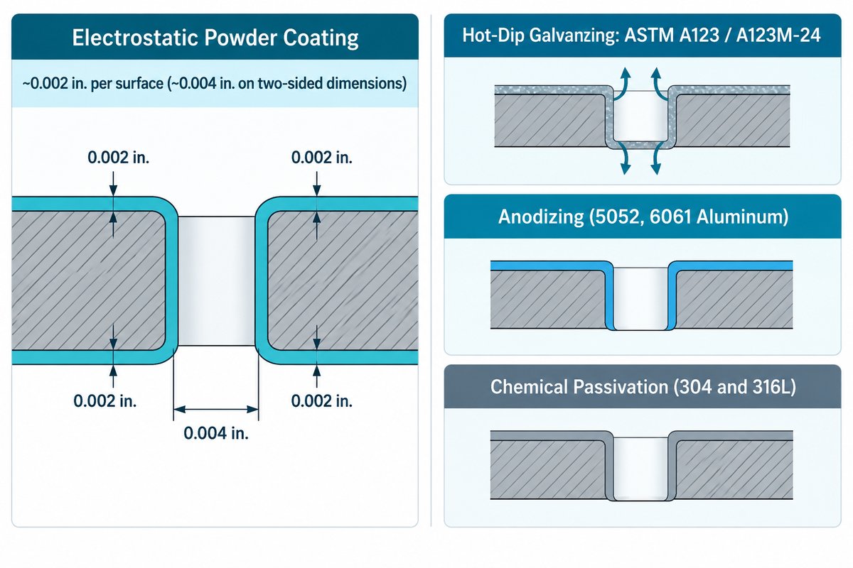
Surface finishing protects fabricated metal products from oxidation and chemical wear while altering final mating dimensions (Approved Sheet Metal). Electrostatic powder coating applies dry thermoset powder that cures into a hard finish, adding measurable thickness to every coated surface of a sheet metal part (Approved Sheet Metal).
If approximately 0.002 in. of powder coating is applied per side, an outside dimension grows by about 0.004 in. (Approved Sheet Metal). An unmasked hole diameter shrinks by that same two-sided build-up. Powder coating film thickness also varies at sharp corners and cutouts due to Faraday cage and overspray effects (Approved Sheet Metal). Precision mating features therefore require masking or pre-coating hole compensation.
For outdoor structural steelwork, material handling racks, and architectural metalwork, hot-dip galvanizing follows ASTM A123/A123M (American Galvanizers Association). The specification covers six steel categories: structural shapes, strip and bar, plate, pipe and tubing, wire, and reinforcing bar (American Galvanizers Association). Hollow steel sections dipped into molten zinc need proper vent and drain holes so air and zinc flow safely (V&S Galvanizing).
| Surface Finish Process | Base Metals | Governing Standard / Build-Up | Mandatory DFM & Masking Rule |
|---|---|---|---|
| Electrostatic Powder Coating | Carbon steel, aluminum, galvanneal | ~0.002 in. per surface (~0.004 in. on two-sided dimensions) | Mask ground studs, PEM threads, and tight dowel bores; account for overspray in cutouts (Approved Sheet Metal) |
| Hot-Dip Galvanizing | Structural shapes, strip, bar, plate, pipe, wire | ASTM A123 / A123M-24 (thickness by steel category) | Provide vent/drain holes in hollow sections; chase or tap internal nuts after dipping (AGA) |
| Anodizing | Aluminum alloys (5052, 6061) | Electrolytic anodic oxide conversion finish | Weld before anodizing; anodic oxide is electrically insulating |
| Chemical Passivation | 304 and 316L stainless steel | Citric or nitric acid treatment to remove free iron | No deposited coating thickness; electropolishing removes surface metal and changes dimensions |
What Dimensional Tolerances and DFM Standards Govern Metal Fabrication Quality?
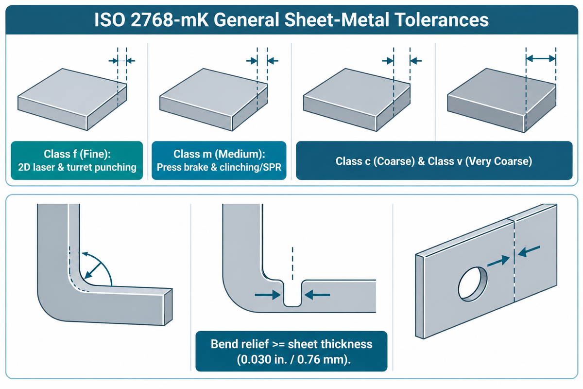
ISO 2768 is the international standard providing general tolerances for linear, angular, and geometrical dimensions on engineering drawings (GD Prototyping). GD Prototyping describes ISO 2768-m as a general sheet-metal tolerance convention. An ISO 2768-mK designation on a drawing specifies the selected general-tolerance classes for features without individual tolerances.
In that designation, class “m” from ISO 2768-1 controls linear and angular dimensions, while class “K” from ISO 2768-2 governs flatness and perpendicularity (GD Prototyping). ISO 2768-mK general tolerances apply when invoked by the drawing or contractual specification. Welded assemblies require dedicated welding tolerance specifications, and individually stated tolerances take precedence. A fiber laser easily holds class “f” (fine) tolerances on flat 2D blanks (GD Prototyping). Press brake bending, however, introduces variation from coil thickness, hardness, and grain direction (GD Prototyping).
There are challenges encountered such as fabrication challenges while switching from designing in 2D to designing in 3D, mainly due to the lack of perspective when visualizing designs. These challenges can be resolved by using the three Design for Manufacturing (DFM) rules.
- Standardize internal bend radii across flanges: Use consistent inside bend radii across flanges where practical, choosing radii compatible with the material grade, temper, thickness, and available tooling (Protolabs). Using compatible radii across flanges avoids extra press brake setups (Protolabs).
- Add corner bend reliefs where flanges intersect: At intersecting flanges, bend reliefs at least as wide as the sheet thickness and extending beyond the bend deformation zone reduce corner bulging and tearing (Protolabs; Newburgh Metals). A 0.030 in. (0.76 mm) relief meets that width rule for sheet no thicker than 0.030 in. (0.76 mm).
- Keep bend lines clear of holes and slots: Keeping bend lines clear of holes and slots reduces stretching during forming (Newburgh Metals). Drawing clearances are from the edge of the hole or slot to the nearest defined limit of the bend deformation zone.
| ISO 2768-1 Class | Precision Level | Achievable Sheet Metal Stage | Cost & Inspection Impact |
|---|---|---|---|
| Class f (Fine) | High-precision tight control | 2D fiber laser cutting and CNC turret punching on flat blanks (GD Prototyping) | Economical on 2D flat features; expensive if applied across multiple bends |
| Class m (Medium) | Industry-standard balance of precision and manufacturability | Standard CNC press brake forming and mechanical clinching/SPR assembly (GD Prototyping) | Common general-tolerance choice (such as ISO 2768-mK when specified on the drawing) for formed sheet metal parts |
| Class c (Coarse) | Relaxed dimensional allowance | Heavy plate plasma cutting, hot-rolled structural brackets, and large frames (GD Prototyping) | Reduces scrap and setup adjustments on non-critical structural metal projects |
| Class v (Very Coarse) | Least restrictive class | Rough castings, forgings, and flame-cut counterweights (GD Prototyping) | Used only where dimensional variation does not affect function |
How Much Does Custom Metal Fabrication Cost Per Hour and What Drives Your Quote?
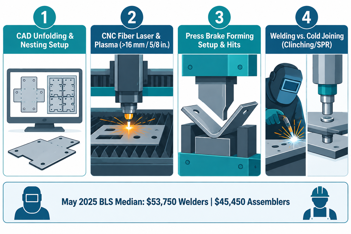
Custom metal fabrication hourly shop rates are project-specific, with quotes built from four cost pillars: raw material nesting yield, direct skilled labor, machine hours, and secondary finishing or inspection. In May 2025, the U.S. median annual wage was $53,750 for welders, Cutters, Solderers, and Brazers, and $45,450 for Assemblers and fabricators (U.S. BLS Welders, U.S. BLS Assemblers).
The overall U.S. employment of Assemblers and fabricators is projected to grow 1 percent from 2025 to 2035 (U.S. BLS Assemblers). Those U.S. BLS wage figures represent individual employee base pay before benefits, machine depreciation, laser assist gas, and shop overhead. Published industry sources don’t set a universal hourly shop rate, so buyers must request a project-specific quote. Comparing fabrication services for commercial projects, the lowest unit bid can raise total cost due to poor DFM and result in assembly rework (Newburgh Metals).
How Much Does Metal Fabrication Cost Per Hour Across Cutting, Bending, and Welding?
Hourly billing rates in a full-service metal fab shop for cutting and bending, and welding, are project-specific. When considering metal fabrication services and sheet metal fabrication services, the best metal fabricators separate a one-time setup NRE from a recurring cycle time. Batch volume, region, and equipment capacity shape commercial shop rates; Table 9 shows the station-level cost drivers that procurement teams can compare across quotations.
| Workstation / Operation | Primary Cost & Labor Driver | Commercial Hourly Rate Basis | DFM Lever to Lower Unit Quote |
|---|---|---|---|
| CAD Unfolding & Nesting Setup | One-time engineering NRE for K-factor, bend reliefs, and nesting layout | Quote amortized across batch quantity | Native 3D CAD files or STEP exports, plus 2D drawings stating the selected general tolerances, such as ISO 2768-mK in GD Prototyping‘s example, and individual limits for critical features |
| CNC Fiber Laser & Plasma Cutting | Machine depreciation, high-pressure nitrogen/oxygen assist gas, pierce count | Request a quote (billed by machine-hour + gas consumption) | Hypertherm reports speed and cost advantages for plasma cutting above 16 mm (5/8 in.); evaluate plasma against laser machine capacity, contour precision, cut quality, and secondary edge-finishing cost |
| Press Brake Forming | Tooling setup time, number of hits per part, and flange flipping ergonomics | Request a quote (setup NRE + cycle time per bend) | Standardize inside bend radii across flanges where practical, using radii compatible with the material grade, temper, thickness, and available tooling (Protolabs) |
| Welding vs. Cold Joining (Clinching/SPR) | BLS reports a median annual wage of $53,750 for U.S. welders, cutters, solderers, and brazers in May 2025; post-weld grinding adds processing work | Quote comparison: manual welding time versus automated joining cycle | Clinching or SPR can replace selected resistance spot welds when two-sided tooling access, sheet ductility, thickness combination, strength, and sealing requirements permit; positioning tack welds serve a different assembly function (TWI) |
RFQ checklist: copy these 8 technical parameters into your custom metal fabrication quote request:
| Parameter & Specification | Recommended Benchmark Input | Why It Prevents Quote Markups | Verification Reference & Standard |
|---|---|---|---|
| 1. 3D CAD & 2D Drawing Package | Native 3D CAD model or STEP (.stp) exchange model + 2D PDF drawing with critical dimensions | Supports flat-pattern development when paired with the shop’s K-factor and V-die library | Protolabs K-factor unfolding rules (Protolabs) |
| 2. Alloy Grade, Temper & Gauge | Exact grade, temper, and thickness, such as 5052-H32 or 6061-T6 aluminum | 6061-T6 generally needs a larger bend radius than 5052-H32; bends perpendicular to the rolling grain reduce cracking risk compared with parallel bends | Atlas Mfg bend radius guide (Atlas Mfg) |
| 3. Inside Bend Radius & Reliefs | Specify an inside radius compatible with the alloy, temper, thickness, and selected V-die; standardize compatible bends and size reliefs for the part | Reduces tooling changes and flange tearing | Confirm against the fabricator’s tooling and material-specific bend guidance (Protolabs) |
| 4. General Tolerance Callout | State the selected general tolerance class on the drawing (such as ISO 2768-mK where selected) plus individual critical feature limits | Avoids costly post-machining caused by blanket CNC milling tolerances on sheet metal | GD Prototyping ISO 2768 guide (GD Prototyping) |
| 5. Joining Method & QC Target | Specify the joining process and its applicable inspection criteria | Where suitable, clinching or SPR avoids welding heat and associated zinc burn-off; welding requires process-specific coating and distortion controls | TWI mechanical joining comparison (TWI) |
| 6. Surface Coating & Masking Map | Allow ~0.002 in. per coated surface for powder coat; specify ASTM A123/A123M for hot-dip galvanizing | Prevents fastener interference and unmasked ground-stud or dowel-hole binding | Approved Sheet Metal & AGA (Approved Sheet Metal; AGA) |
| 7. Quality Management Certification | ISO 9001:2015 or aerospace AS9100D certification within its certified scope; FAI report | Certification provides evidence of a quality management system, while the FAI report documents first-article inspection results | Fabcon quality standard baseline (Fabcon) |
| 8. Batch Quantities & Packaging | Quote prototype lot (1–10 pcs) alongside production release tiers (100–5,000 pcs) | Separates one-time CAM/tooling setup NRE from recurring per-piece cycle cost | Newburgh Metals quoting guide (Newburgh Metals) |
Integration & Utility Requirements: Sizing Presses and Automated Joining Cells for Your Shop Floor
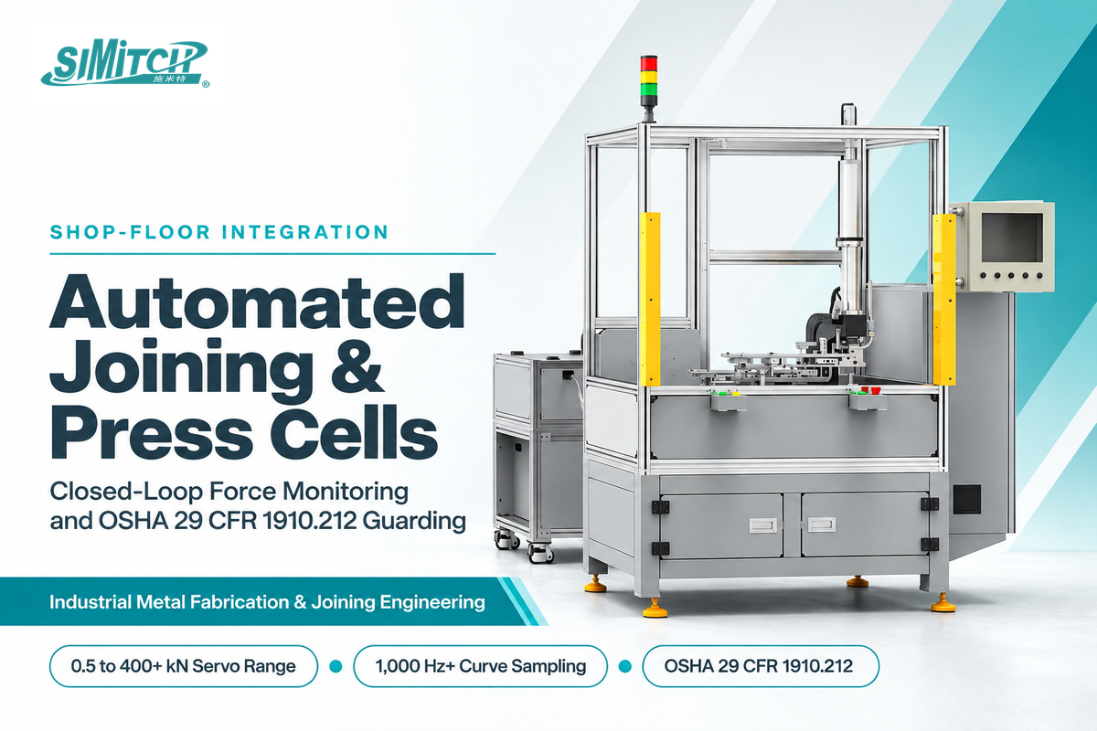
Global industrial robot installations reached 542,076 units in 2024 as fabrication facilities adopted flexible robotics, cobots, and automated joining cells to address labor shortages (MachineSource Global). Upgrading from manual arbor presses for low-force benchtop staking to automated pressing and cold-joining workstations requires matching drive utilities, closed-loop sensors, and machine guarding.
The force-range of servo pressing systems can be as low as 0.5 kN and as high as 400+ kN, with approach speeds of 50-200 mm/s (AMD Machines). In automated pressing systems, the approach and stop speeds can be controlled as low as 0.5 mm/s for press-fits (AMD Machines). AMD Machines describes servo press systems that record force-displacement signatures at sampling rates of 1,000 Hz or higher for in-process monitoring. Sheet-to-sheet joining can be automated using fastener-free clinching and electrical self-pierce riveting systems, which can also be integrated to industrial robots (Böllhoff).
Integrating forming and joining machinery into a U.S. fabrication facility requires compliance with machine-specific OSHA regulations showing a commitment to safety. Mechanical flywheel stamping presses fall under 29 CFR 1910.217, whereas press brakes, hydraulic and pneumatic presses, and riveting machines are excluded under 29 CFR 1910.217(a)(5) (OSHA 1910.212). Those excluded machines are governed by OSHA 29 CFR 1910.212 general machine guarding. Under 29 CFR 1910.212, machine guarding must protect operators from point-of-operation hazards, ingoing nip points, rotating parts, and flying chips (OSHA 1910.212). On power press brakes where workpiece geometry makes physical barriers infeasible, OSHA Directive CPL 02-01-025 permits safe-distance safeguarding (OSHA CPL 02-01-025). The employer must demonstrate barrier infeasibility and follow ANSI B11.3 guidelines (OSHA CPL 02-01-025).
| Workcell Equipment Type | Force & Speed Envelope | In-Process Quality Monitoring | Safety Guarding & Regulatory Standard |
|---|---|---|---|
| Industrial Servo Assembly Press | Servo press systems span 0.5 kN to 400+ kN, with typical approach speeds of 50–200 mm/s and insertion speeds as low as 0.5 mm/s for delicate press-fits (AMD Machines) | Closed-loop load cell + encoder curve sampling at 1,000 Hz or higher (AMD Machines) | Point-of-operation guarding selected through a machine risk assessment under OSHA 29 CFR 1910.212 |
| Pneumohydraulic & Servo Clinching Machines | C-frame throat sized to flange reach; compressed air or electric servo drive | Force-displacement window + non-destructive button thickness (X-value) gauge | Point-of-operation guarding and safety stroke clearance under OSHA 29 CFR 1910.212 (OSHA) |
| Automated Self-Piercing Riveting (SPR) Cells | Pedestal or robot-mounted C-frame with automatic rivet feeder tube (US9015920B2) | Variable clamp force control (US20230041416A1) + periodic cross-sectioning | Perimeter safety fence with interlocked gates and dual-channel safe torque off |
| CNC Power Press Brake | Hydraulic or servo-electric ram with 0.0004-in. precision ground V-dies (The Fabricator) | In-process laser angle measurement and CNC crowning compensation | OSHA 29 CFR 1910.212 & Directive CPL 02-01-025 / ANSI B11.3 safeguarding (OSHA CPL 02-01-025) |
As a specialized equipment supplier and fabrication solutions partner, Suzhou Simitch Machinery Co., Ltd. (SIMITCH) offers clinching machines, self-piercing riveting systems, hydro-pneumatic cylinders, and precision servo presses. Whether you operate a custom sheet metal fabrication company, a structural fabricator and erector, or an automotive tier-one company specializing in lightweight enclosures, matching cutting and bending tolerances to assembly requirements can reduce fit-up rework. Cold mechanical joining also avoids welding-induced thermal distortion in suitable sheet-metal joints.
Frequently Asked Questions
Q: What is the meaning of metal fabrication?
Metal fabrication is the value-added manufacturing process of turning raw flat sheet metal, structural plate, bars and tube stock into finished components or assemblies.
Metal fabrication unites numerous processes together, including layout and CAD nesting, cutting, bending, joining, and protective surface finishing (NAMF). Machining can also be part of fabrication.
Q: What do metal fabricators do on a daily basis?
Metal fabricators read 2D engineering drawings and 3D CAD models, calculate flat-pattern bend deductions, program CNC fiber lasers or turret punches, form flanges on press brakes, and assemble parts. They assemble parts.
Depending on the alloy, they join sub-assemblies using MIG/TIG welding services, resistance spot welding, or cold mechanical clinching. They then deburr edges and verify dimensions against drawing-specified tolerances, such as ISO 2768-mK when called out on sheet-metal prints (GD Prototyping). Welded structural assemblies require separate welding tolerance specifications.
Q: Is metal fabrication the same as welding?
No, metal fabrication and welding are not the same. Metal fabrication incorporates the entire process from cutting raw material to press brake bending, forming and assembly as well as surface coating (Southern Metal Fabricators).
Welding is the type of thermal joining technique used during the assembly process, along with other mechanical fastening techniques like self-piercing riveting and clinching (TWI).
Q: What are the three main types of metal fabrication?
By application scale, the three main categories are structural metal fabrication, industrial metal fabrication, and precision sheet metal fabrication. Structural shops build building frames and bridges, industrial shops build heavy machinery skids, and commercial sheet-metal shops build enclosures, ductwork, and brackets.
Q: When should you use sheet metal clinching or self-piercing rivets instead of spot welding?
Engineers specify sheet metal clinching or self-piercing riveting (SPR) instead of resistance spot welding when joining pre-painted panels, galvanized steel, aluminum, or dissimilar metal stacks (TWI).
Clinching and SPR form mechanical interlocks without welding heat, avoiding thermal distortion, zinc burn-off, and copper electrode wear (Assembly Magazine). They allow real-time force-displacement monitoring, though local deformation or piercing can still disrupt the zinc coating at the joint.
Q: What is the standard tolerance for sheet metal fabrication?
GD Prototyping describes ISO 2768-m as a general sheet-metal tolerance convention, where class “m” controls linear and angular dimensions and class “K” governs flatness and perpendicularity. General tolerances apply only when stated on the drawing or contract.
Q: What files and details do you need to request a custom metal fabrication quote?
A custom metal fabrication RFQ can include a native 3D CAD model or a STEP (.stp) exchange model and a 2D PDF drawing with thread callouts and specified tolerances (such as ISO 2768-mK where selected). The package should also state exact material specifications, such as 5052-H32 aluminum or cold-rolled steel with its thickness stated. Flat-pattern development also needs bend allowances.
Joining method (SPR, clinching or welding), surface finish and masking location ( 0.002″ for each side for powder coating) and batch size should be specified (Approved Sheet Metal).
Need Automated Clinching, Self-Piercing Riveting, or Servo Press Equipment for Your Fabrication Line?
SIMITCH engineers configure clinching machines, SPR workstations, and closed-loop servo presses for sheet metal fabrication facilities to join galvanized HVAC ducts, appliance panels, automotive aluminum-to-steel structures, and press-fit assemblies.
Why We Wrote This Engineering Guide
We compiled this metal fabrication guide to help designers, engineers, and buyers connect flat-pattern cutting, press brake forming, and cold mechanical joining. This guide draws on OSHA 29 CFR 1910.212 for machine guarding, U.S. BLS wage data for labor benchmarks, ASTM A123/A123M for hot-dip galvanized coatings, ISO 2768 for general tolerances, and TWI joining research. Equipment parameters come from AMD Machines, while bending guidance draws on fabricators and The Fabricator. Reviewed by the Suzhou Simitch Machinery Co., Ltd. technical engineering team.
References & Sources
- 29 CFR 1910.212: General Requirements for All Machines (Machine Guarding) Occupational Safety and Health Administration (OSHA)
- OSHA Directive CPL 02-01-025: Guidelines for Point of Operation Guarding of Power Press Brakes Occupational Safety and Health Administration (OSHA)
- Occupational Outlook Handbook: Welders, Cutters, Solderers, and Brazers U.S. Bureau of Labor Statistics (BLS)
- Occupational Outlook Handbook: Assemblers and Fabricators U.S. Bureau of Labor Statistics (BLS)
- Plasma vs. Laser Cutting: Thickness, Tolerance, and Cost Comparison Hypertherm
- Choosing a Cutting Process: Plasma, Laser, Waterjet, and Oxyfuel Hypertherm
- Industrial Servo Pressing Systems & Force-Displacement Monitoring AMD Machines
- RIVSET Self-Pierce Riveting and RIVCLINCH Mechanical Joining Technology Böllhoff
- Sheet Metal Bend Radius Guide: Minimum Bend Radius by Material and Thickness Atlas Manufacturing
- The Impact of Powder Coating on Tolerances for a Metal Fabricated Part Approved Sheet Metal
- Best Practices in Designing Thickness and Bend Radius Practical Machinist Forum
- The Future of Metal Fabrication in 2026: Key Trends and Automation MachineSource Global
- Sheet Metal Tolerance Standards & Quality Certifications Fabcon
- A Guide to Sheet Metal Tolerances (ISO 2768-1 and ISO 2768-2) GD Prototyping
- ASTM A123/A123M Specification for Hot-Dip Galvanized Coatings on Iron and Steel American Galvanizers Association (AGA)
- ASTM A123-24 Key Changes to the Hot-Dip Galvanizing Specification V&S Galvanizing
- The Rules of Press Brake Tool Selection (Rule of 8 V-Die Opening) The Fabricator (FMA)
- How Do Clinching and Self-Piercing Riveting Compare With Spot Welding for Sheet Materials? TWI (The Welding Institute)
- What Is Fabrication? Definition, Processes, and Examples TWI (The Welding Institute)
- Alternatives to Resistance Spot Welding for Joining Sheet Metal Assembly Magazine
- The Basics of Bend Radii, K-Factor, and Bend Reliefs in Sheet Metal Protolabs
- Common Sheet Metal Fabrication Mistakes and How to Avoid Them Newburgh Metals
- The Metal Fabrication Process: 5 Core Stages NAMF
- What Is Metal Fabrication? Phases and Value-Added Operations Southern Metal Fabricators
- U.S. Patent US9015920B2: Self-Piercing Riveting System and Process Google Patents
- U.S. Patent Publication US20230041416A1: Mechanically Joining Advanced High Strength Steel Google Patents