Get in touch with Suzhou Simitch Machinery Co., Ltd Company

Press fit tolerance describes the permissible dimensional variations of mating features. Interference is the shaft diameter minus the hole diameter. A useful specification states both parts’ limits, and connects the result to inspection and joint function.
Quick Specs: hypothetical drawing
Shaft: 25.020–25.030 mm. Hole: 25.000–25.010 mm. Calculated diametral interference: 10–30 μm. No standard fit class or press capacity is assigned.
Press fit tolerance needs four dimensional limits. Minimum interference = smallest shaft − largest hole; maximum = largest shaft − smallest hole. Use matching units and measurement conditions. Positive results establish dimensional interference, not joint performance.
- A negative minimum doesn’t always mean a transition fit; the maximum should also be checked.
- Diameter limits of features of joints don’t fully define form and surface requirements.
- An acceptable press trace requires a verified relationship to the finished joint results.
Define press fit tolerance before choosing a number
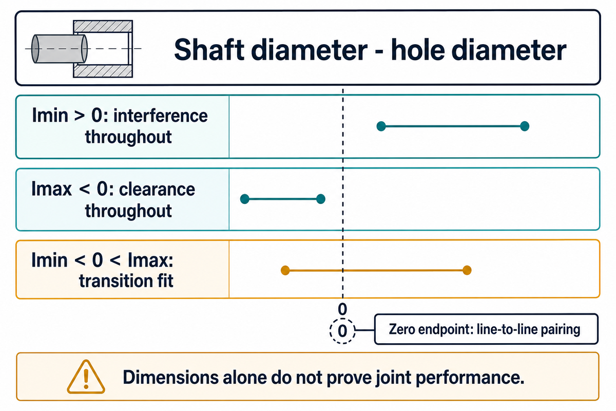
A press fit specification requires separate shaft and hole tolerances, since either part may vary within its permitted limits. The resulting interference fit describes their dimensional relationship. Whether that relationship can hold the parts under service loading requires material, geometry, and functional evidence beyond the size calculation.
With a positive interference fit, the shaft is oversized relative to the bore. When a joint is assembled, pressure occurs, and the useful frictional resistance depends on the joint design and surfaces.
| Interval | Dimensional relationship | Reader action |
|---|---|---|
| Imin > 0 | Interference throughout | Check whether the joint tolerates both extremes. |
| Imax < 0 | Clearance fit throughout | Check the required freedom of movement. |
| Imin < 0 < Imax | Transition fit | Allow for either interference or clearance. |
An endpoint of zero allows a line-to-line dimensional pairing. A sliding fit or slip fit has a different functional effect from a retained joint; hand effort is not its dimensional definition. ISO 286-2:2010 defines the limits of the shaft and hole, but to define a complete specification, the applicable requirements must be stated.
Writing “press fit” beside a 25 mm nominal dimension leaves the permitted variation unknown. Treat each part separately, noting its limits and the assembled joint’s function. This is for smooth, cylindrical surfaces. Splines, knurls and tapered interfaces, for example, require their own dimensional and installation requirements.
Calculate minimum and maximum interference from four limits
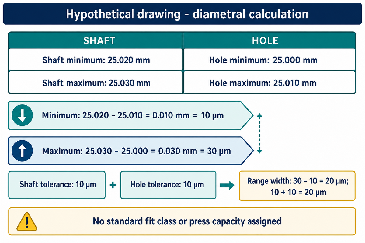
In this case, the least amount of interference is achieved by the smallest possible shaft and the largest possible hole. The most amount of interference is achieved by the largest possible shaft and the smallest possible hole. Both of these combinations should be considered in the same unit of length and at the specified measurement state. These extremes define the limits of the drawing. They don’t predict how frequently production will produce parts at these dimensional limits.
How do dimensional tolerances create minimum and maximum interference?
Each component has its own allowed variation, so a nominal difference can’t describe all permitted pairings. Convert any plus/minus dimension or limit deviation into explicit minimum and maximum sizes first. Then subtract opposite limits from each other. The interference interval width is the sum of the component tolerances.
Take inputs from the specified hole-and-shaft limits system. For this hypothetical metric worksheet, diameters are assumed in an agreed measurement state, not in the values given in the ISO tables.
Four-Limit Fit Worksheet
| Field | Hypothetical example / calculation | Your drawing entry or check |
|---|---|---|
| Shaft minimum, Smin | 25.020 mm | Enter lower limit and drawing revision. |
| Shaft maximum, Smax | 25.030 mm | Enter upper limit and drawing revision. |
| Hole minimum, Hmin | 25.000 mm | Enter lower limit and drawing revision. |
| Hole maximum, Hmax | 25.010 mm | Enter upper limit and drawing revision. |
| Shaft tolerance | 25.030 − 25.020 = 0.010 mm = 10 μm | Calculate Smax − Smin. |
| Hole tolerance | 25.010 − 25.000 = 0.010 mm = 10 μm | Calculate Hmax − Hmin. |
| Minimum diametral interference | 25.020 − 25.010 = 0.010 mm = 10 μm | Calculate Smin − Hmax. |
| Maximum diametral interference | 25.030 − 25.000 = 0.030 mm = 30 μm | Calculate Smax − Hmin. |
| Interference-range width check | 30 − 10 = 20 μm; 10 + 10 = 20 μm | Confirm the range width equals the component tolerance sum. |
Hypothetical drawing example: an engineer hands quality a drawing that permits a 25.020–25.030 mm shaft and a 25.000–25.010 mm hole. Quality calculates the loosest combination as 25.020 − 25.010 = 0.010 mm, or 10 μm. The tightest combination is 25.030 − 25.000 = 0.030 mm, or 30 μm. Subtracting the endpoints gives a 20 μm interval, equal to the two 10 μm component tolerances added together. Both endpoints are positive, so the permitted dimensional interval is entirely interference. The engineer now supplies the material condition, form requirements, and acceptance criteria. The arithmetic is consistent; nobody has yet measured parts, established holding performance, or selected a machine. That distinction belongs on the trial request.
Correct any input limits that are expressed incorrectly, prior to calculation. Don’t replace drawing extremes with a root-sum-square estimate. Radial interference is defined as half the diametral difference in this case, but neither of these quantities individually defines the insertion force.
Key takeaway
The hypothetical 10–30 μm interval proves a consistent dimensional stack. Approval still needs defined geometry, measurement decisions, and evidence that the assembled joint meets its intended function.
Read ISO 286 and FN fit classes without false equivalence
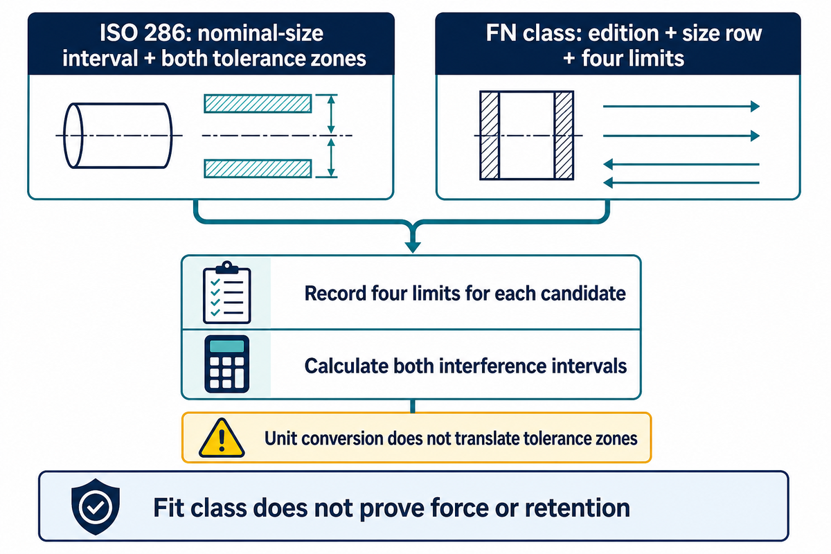
Evaluate the fit class using the standard, edition, and nominal-size interval specified on the drawing. Extract shaft and hole limits before comparing alternatives. A fit class identifies a dimensional selection, but doesn’t demonstrate assembly force, retention or equivalence to another standards system.
What is the difference between FN1 and FN2 press fits?
Compare FN1 and FN2 limits in the given standard and nominal size row. Record the four limits for each candidate and calculate the two interference intervals. Without those entries, the labels alone do not justify a numerical difference, an ISO equivalent, or a recommendation for a particular press capacity.
The public description of ASME B4.1, Preferred Limits and Fits for Cylindrical Parts, identifies its scope. Neither that description nor ISO’s public introduction supplies the required numerical tables.
| Reference | Retrieve | Does not prove |
|---|---|---|
| ISO 286 designation | Nominal-size interval and both tolerance zones | Suitability for every material or wall thickness |
| Drawing-specified FN class | Edition, size row, and four limits | A universal ISO interchange |
| Engineering handbook | Its cited standard and matching table units | That an unlabeled chart matches the purchase specification |
It requires design review to approve a purchasing request to replace FN1 with H7/p6. Converting inches to millimeters preserves a length; it doesn’t provide a translation of tolerance zones. Ask the supplier to return limits and the governing reference, and don’t accept “industry standard” as the answer.
A 25 mm nominal diameter locates a size row only after the governing standard is known. The worked 10–30 μm range carries no FN or ISO class assignment. Compare documented limits first, then judge the engineering consequences of either proposed fit.
Judge interference against material and geometry
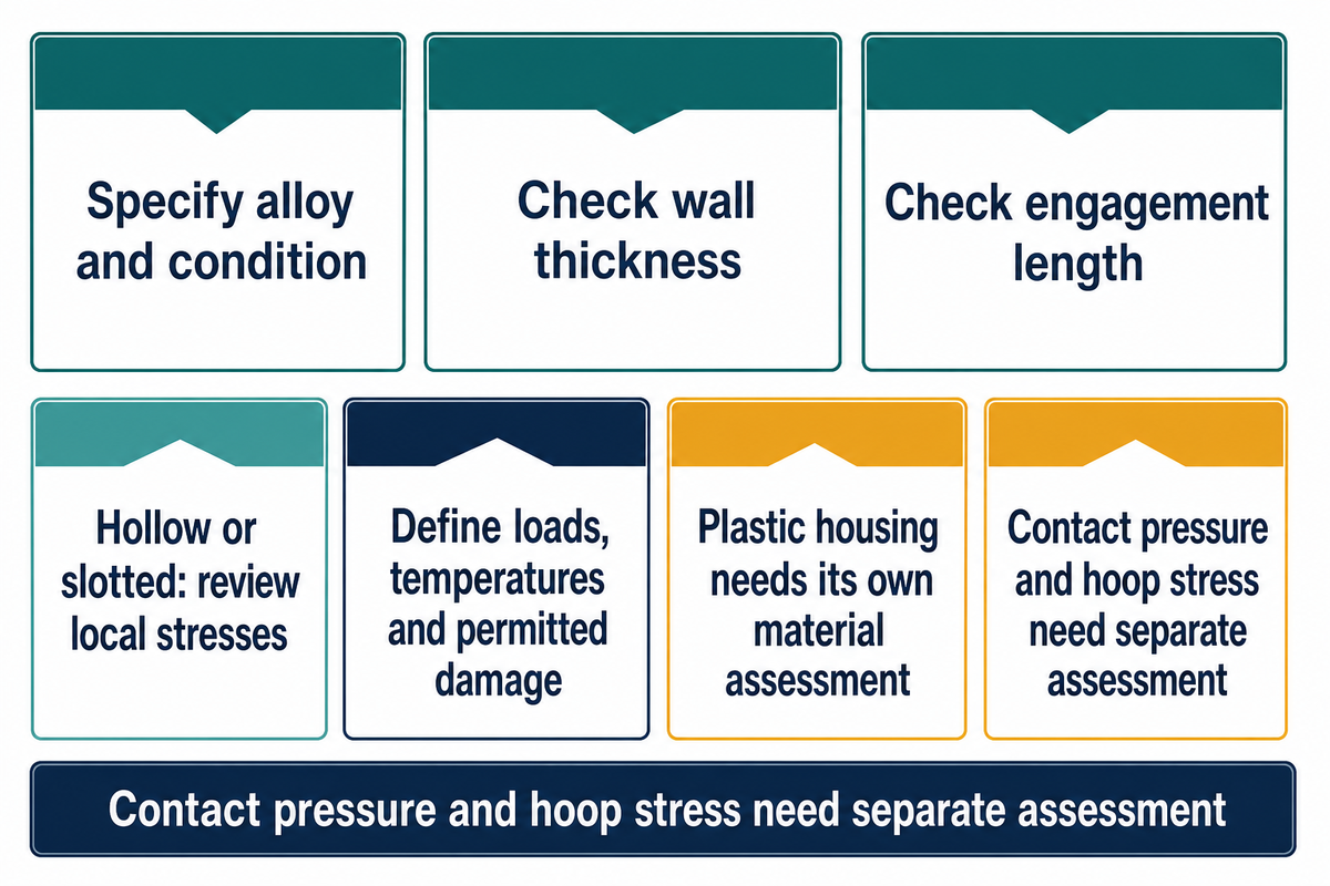
An interference value is only acceptable with a defined set of criteria (material, geometry, service conditions, etc). Diameter alone can’t describe the stiffness of a thin housing or a hollow shaft. Prior to approving a number, determine how the parts deform and what loads, temperatures, and damage limits the assembled joint is expected to withstand.
Is .002 a good press fit?
A bare “.002” is insufficient because its unit and dimensional convention are missing. A diametral difference of .002 in equals 0.0508 mm, or 50.8 μm; .002 mm equals only 2 μm. Neither conversion establishes a suitable fit. Approval still needs the diameter, materials, wall thickness, engagement length, and required joint function.
Contact pressure and hoop stress require a separate engineering assessment. The material inputs to be considered may include the Young’s modulus and strength data for the specified alloy and condition. An axial retention requirement also needs the relevant interface and loading assumptions. No pressure formula is inferred from the worksheet.
| Condition | Required action | Limitations / Not suitable for |
|---|---|---|
| Steel shaft, aluminum housing | Confirm alloys, walls, and service temperature range. | A generic material-name correction cannot approve the joint. |
| Hollow or locally slotted section | Check compliance and local stresses with the design owner. | Solid cylindrical assumptions may not apply. |
| Bronze or cast iron component | Obtain the specified grade and permitted damage criteria. | Material names do not establish allowable compression. |
Castagnetti and Dragoni’s 2024 finite-plate study shows that the geometric proportions and pin offsets can affect the contact-pressure distribution. A same-material, linear-elastic, two-dimensional model in a plane-stress state without external loading supports checking the circular-hub assumptions, not transferring values to arbitrary joints.
Plastic press fit tolerance requires its own material and service assessment. Metal-fit rules shouldn’t be applied to a plastic housing. Request the supplier data for the specified grade under the intended temperature and time conditions, and confirm retention for that duty. Results of an installation shouldn’t be relied on to demonstrate long-term holding performance.
A familiar 0.001 in-per-inch rule can’t resolve missing geometry or service data. An alternative like a keyway, or a bolt that provides removable retention, also needs design approval. Specify the required function before choosing the joining method.
Approving 50.8 μm because it = .002” would be confusing conversion and design validation. A buyer needs the missing material and geometry data returned with the proposal. The right fit is the interval that supports the required function, with supporting analysis or tests.
Separate bearing seats, solid pins, and spring pins
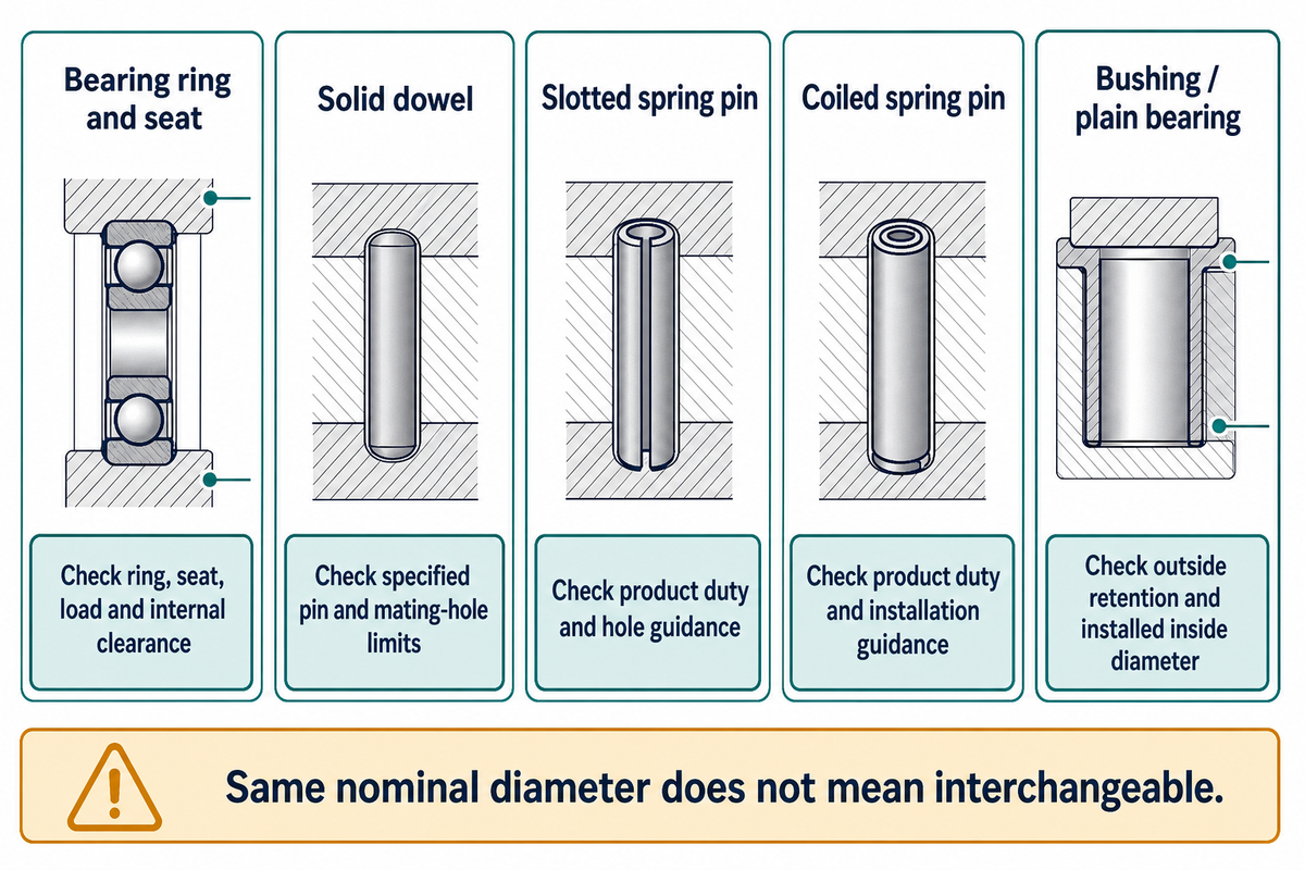
Bearing seats, spring pins and solid pins need different selection evidence, as the interfaces and deformation are different. Obtain the product drawing and guidance on how a component will be installed before defining a hole tolerance. Equal nominal diameters don’t make the parts interchangeable and a fit around one part may damage another.
What is the acceptable tolerance for press fit pins?
The specified pin tolerance is the one that’s right for the material and the hole function, as well as the retention for that product. Identify if the pin is solid, slotted, or coiled and then check the limits. Next, verify the manufacturer’s hole recommendation and installation constraints; a generic interference band can’t cover all three mechanisms.
| Component | Evidence needed | Do not transfer |
|---|---|---|
| Bearing ring and seat | Ring tolerances, loading relative to the ring, seat limits, and internal clearance | A generic shaft/hole pairing |
| Solid dowel | Specified pin and mating-hole limits; ISO 8734 covers particular hardened steel and martensitic stainless steel dowels | Spring-pin hole recommendations |
| Slotted spring pin | Product duty and hole guidance; ISO 8752 identifies the heavy-duty slotted family | A universal rule for every spring pin |
| Coiled spring pin | Product duty and installation guidance; ISO 8750 identifies the standard-duty coiled family | Solid-pin interference values |
| Bushing / plain bearing | Outside-diameter retention and installed inside-diameter requirements | Approval based only on the uninstalled bore |
SPIROL’s published hole-preparation guidance differentiates solid pin sizing from spring pin compression. The product mechanism differentiation explains why changing suppliers requires a drawing comparison, even if both pins locate the same parts together.
A bearing interference fit requires the limits of the ring and its seat. Check the bearing housing fit and the inner-ring/shaft interface separately. The ring’s tendency to rotate relative to its load is critical. C3 describes an internal clearance group, not a seat fit class.
A bushing interference fit controls outside-diameter retention. Check the installed running fit inside the bushing separately, because an acceptable uninstalled bore doesn’t prove the final internal dimension.
NASA/TM-2009-215285 examines interference-related hoop stresses and the fatigue life of cylindrical roller bearings through calculations. Its abstract allows the treatment of bearing life as a different design consideration. It provides no universal life factor for ball bearing seats, dowels, or the joint of interest to the reader.
When providing bearing guidance, SKF states that thin-walled housings or hollow shafts may actually require tighter interference fits than cast-iron housings with thicker walls or solid shafts. Don’t take a thin-wall warning to mean a looser fit is allowed. Always apply the supplier’s recommendation regarding interference fits to the actual support geometry and check ring distortion separately.
Dowel pin interference fits require review when a supplier change occurs, even at the same nominal diameter. Make sure to return the proposed pin drawing to the design owner and confirm the limits of the hole and installation guidance before substitution. Be especially clear and precise when near a limit.
Measure the parts before trusting the fit range
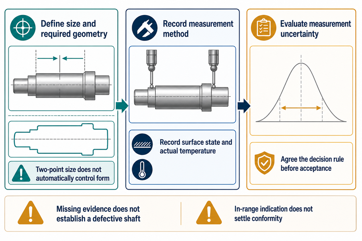
A calculated fit range is only useful if inspection measures the size defined in the drawing under the relevant conditions. State the conditions, the measurement locations and method, the state of the surface, and the temperature along with the result. As a general rule, form limits and the agreed-upon rule for measurement uncertainty dictate what the result can support, particularly if it’s close to a limit.
It is shown in the ISO 286-2 public introduction that the default two-point size criterion does not automatically control form. A roundness, cylindricity, envelope, or surface requirement may be needed to achieve the intended fit, but the appropriate drawing controls depend on function.
“This means that form is no longer controlled by the default specification of size.”
A machinist checking OD in one direction has measured that feature with that method. The result can’t describe every contact point along an interface with taper or form variation. Design should define the required geometry and metrology should choose a method that addresses it.
Measurement decisions are a separate issue. According to NIST’s Measurement Uncertainty guidance, uncertainty always expresses incomplete knowledge of the measured quantity. Therefore, a gauge display should always have an associated uncertainty and a defined measurand, as opposed to simply displaying digits and comparing them with an upper or lower limit.
ASME B89.7.3.1 addresses decision rules that consider uncertainty when determining conformity. Supplier and customer should agree on the rule before acceptance. No universal guard band or gauge ratio is assigned here; a boundary indication follows the agreed accept, reject, or further-measurement decision.
Hypothetical inspection scenario: A shaft reads near its drawing upper limit, and two directional measurements fall within the stated range. The report contains no record regarding the applicable envelope or cylindricity requirements, and the current measurement method lacks an agreed uncertainty decision rule. Quality doesn’t declare the shaft defective due to the absence of these items alone. The design owner first confirms the size definition and required geometry, and then metrology checks the measurement method and its uncertainty. The missing rule is then resolved by the acceptance owner in consultation with the customer prior to making a final disposition. Selecting the most favorable repeat reading would change the decision basis. The evidence available supports the indications reported, but doesn’t yet support the unresolved conformity decision.
CNC manufacturing tolerances also need a stated surface condition. Specify whether sizes apply before or after coating, record surface roughness requirements, and assess burrs. Tight tolerances don’t compensate for a measurement made on the wrong surface state.
In NIST’s account of the dimensional reference temperature, 20°C is defined as the standard temperature. Record the actual part temperatures and evaluate temperature changes with the relevant material coefficient. Differential expansion requires application inputs; 20°C isn’t an allowed temperature variation in the workshop.
Engineering Note
For the hypothetical 25.030 mm shaft upper limit, an in-range indication doesn’t settle an undefined form requirement or uncertainty decision. The purchase order should name the applicable inspection method and decision rule before parts arrive.
Link fit limits to assembly evidence and failure causes
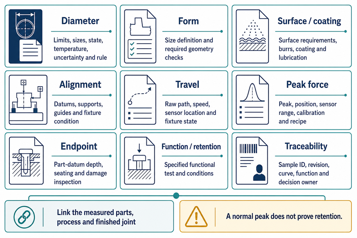
Assembly evidence should connect the measured components, the process, and the finished joints through the same sample identity. A force-displacement trace shows how parts are pressed together, while depth and functional tests answer different questions. Unusual curves on a graph should be investigated until it’s determined which factor is actually responsible for the observed results.
We describe process monitoring and external sensor options in our BP precision assembly press page. Those features help collect evidence; how useful they are depends on whether sample labels are validated, the behavior of the fixture, and where measurements are made.
When installing bearings, link each pressing record to the relevant ring and seat measurements. The functional checks of the selected bearing remain part of the acceptance plan.
0.01 mmSIMITCH stated repeat positioning, not part tolerance
Up to 10 kHzSIMITCH stated acquisition rate, not control bandwidth
Up to 4 windowsSIMITCH stated evaluation capacity; validate thresholds
Fit-to-Proof Evidence Matrix
This editorial checklist assigns evidence to failure modes. Dimensional rows address size and conformity; process rows require application trials. Replace each role with a project owner.
| Object | Trigger / candidate issue | Evidence to retain | Responsible role | Limitations |
|---|---|---|---|---|
| Diameter | Boundary indication or changed interval | Four limits, measured sizes, state, temperature, uncertainty, agreed rule | Metrology / quality | Display values alone establish neither conformity nor form. |
| Form | Local binding despite similar diameters | Size definition and applicable envelope, roundness, or cylindricity checks | Design / metrology | Few two-point readings cannot describe full-length contact. |
| Surface / coating | Machining batch or coating change | Surface requirements, burr checks, coating state, lubrication | Manufacturing / quality | Records do not quantify effective interference or friction. |
| Alignment | Early contact, side loading, scoring | Datum setup, supports, guides, entry position, fixture condition | Process / tooling | Contact anomalies do not identify one dimensional cause. |
| Travel | Changed insertion path or pause | Raw force-displacement path, speed segments, sensor location, fixture state | Process / controls | Machine movement may include system deflection. |
| Peak force | Maximum force outside the validated window | Peak and position, sensor range, calibration, recipe | Process quality | A normal peak does not approve the full stroke or retention. |
| Endpoint | Normal command but questionable seating | Part-datum depth, shoulder seating, permitted-damage inspection | Inspection / assembly | Machine endpoint cannot establish finished dimensions or sealing. |
| Function / retention | Service risk despite dimensional and curve acceptance | Specified retention, push-out, operation, or relevant functional test and conditions | Product design / quality | One test does not cover all temperatures, life, or batches. |
| Traceability | Result cannot be linked to its part or revision | Sample ID, drawing, recipe, sizes, curve, function result, decision owner and time | Quality systems / production | Complete records cannot make an incorrect design valid. |
Common failure modes: a normal trace can leave a question open
Hypothetical trial scenario: steel shafts enter aluminum housings with peak force and machine end points within the project’s existing windows. The product engineer notices that the required retention result is missing. In this example, the trace isn’t treated as a failed joint, but it is no substitute for the absent test. Each sample ID is linked to four limits, the measurement state, fixture checks and complete curve. Inspection records depth relative to the part datum. The responsible team performs the application-required retention or functional test and evaluates the result using the criteria defined for the project. An assembly trace can be provided to support acceptance once the relationship to the relevant defect is validated. That relationship has not been established by the missing record in this teaching example.
Promess engineering manager John Lytle’s 2024 article, “How to Evaluate a Press-Fit Curve,” provides insight on establishing a baseline by using a known-good component or a set of acceptable components. Once those samples are confirmed against the required joint tests, their curves can be used to set limits on production. Averaging an unverified batch doesn’t verify that the joints of the batch are acceptable.
Initial resistance may suggest misalignment or a surface issue; easily damaged parts should be inspected after pressing. A looser trace may suggest a changed interface; however, it isn’t proof of root cause. SIMITCH’s published trial guidance calls for sample validation before release.
Production wants fewer stops. Quality needs evidence about missed defects and false rejects. Finance needs trial, scrap, rework, and downtime costs from the same records. Before buying more capacity, compare press drive options against the process requirements; monitoring can also be applied to other press types.
Prepare a tolerance-led servo press trial
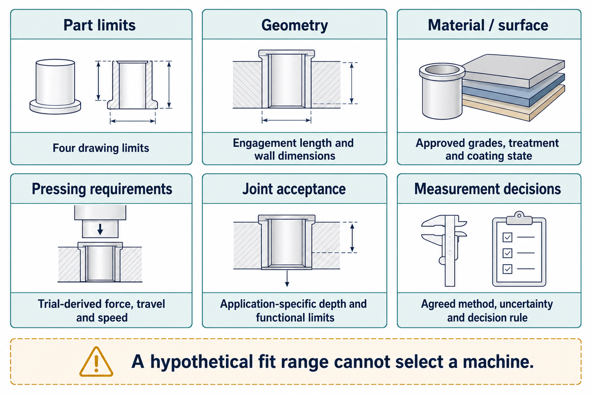
A written acceptance plan and a set of controlled part requirements are a good way to start a useful servo press trial. Send the supplier the dimensional limits, material condition, geometry, and measurement records with representative part samples. Agreement should be reached regarding which tests establish joint function, and which records establish process control prior to selecting equipment or negotiating production acceptance.
The servo press RFQ checklist is available to assist in organizing a quotation package. Blank fields in the checklist should be completed; unassigned fields should be identified and assigned to the responsible engineer.
| Parameter | Recommended range | Why it matters | How to verify |
|---|---|---|---|
| Part limits | Four drawing limits in mm or in | Defines permitted pairings | Design: signed revision and worksheet |
| Geometry | Engagement length and wall dimensions in mm | Defines support and compliance | Design / tooling: part drawing |
| Material / surface | Approved grades, treatment, coating state | Changes deformation and interface behavior | Quality: material and process records |
| Pressing requirements | Trial-derived force in kN, travel in mm, speed in mm/s | Bounds equipment selection | Supplier / process: recorded trials |
| Joint acceptance | Application-specific depth and functional limits | Defines acceptable output | Product engineering: approved test plan |
| Measurement decisions | Agreed method, uncertainty, and decision rule | Prevents conflicting dispositions | Customer / supplier quality: written agreement |
ASME’s decision-rule guidance supports the measurement agreement but isn’t a basis for an entire machine-acceptance procedure. Choose sample coverage according to dimensional variation, known defects, and application criticality; no fixed sample count proves every process.
Isolate tooling, metrology, sample trials and integration in the quote to allow finance to assess the scope. An arbor press or hydraulic system may be suited to the job; servo control requires its own business and technical case. Preliminary BP sizing may help in discussing scope after required inputs are known.
A 10–30 μm hypothetical fit range can’t select a machine. Trials must establish the relevant force, travel, and measurement requirements. Review manufacturability with the supplier before purchase, then price the evidence needed to achieve acceptance alongside the equipment that will assemble the parts.
Frequently asked questions
What tolerances are needed for push fits?
A push fit intended to slide into place needs clearance suited to its function, rather than an assumed interference value.
Clarify whether “push” means free sliding, accurate location, or a retained component installed by hand. Those requirements can lead to different fit tolerances. Specify both mating limits and check the least available clearance under the relevant conditions. Surface condition and geometric alignment still matter when parts must move freely. Hand effort alone can’t define the permitted interval or prove repeatable assembly.
Can you give me an example of a transition fit in engineering?
A hypothetical shaft of 10.000–10.010 mm paired with a hole of 10.005–10.015 mm permits both clearance and interference.
Minimum interference is 10.000 − 10.015 = −0.015 mm, or −15 μm. Maximum interference is 10.010 − 10.005 = +0.005 mm, or +5 μm. Because the interval crosses zero, the permitted pairings include both dimensional outcomes. A production plan must accommodate that variation. These invented limits illustrate classification only; they don’t identify a standard class or approve a specific application.
How to find press fit/ slip fit for non standard size parts?
Start with the governing standard’s applicable nominal-size interval, then document achievable limits and the required joint function.
A nonstandard nominal size doesn’t remove the need for explicit upper and lower limits. Have design and manufacturing confirm the proposed tolerances against available processes, inspection capability, and the selected product guidance. If a standard-table choice is unsuitable, state the approved limits directly. Keep the measurement state and acceptance rule with the specification so a supplier can evaluate the complete requirement.
Can press fit tolerance be adjusted?
Yes, through an approved change to component limits or manufacturing processes followed by suitable verification.
Review machining and coating changes against joint function. Increasing press force doesn’t revise the permitted dimensions. Record the new drawing revision and repeat the affected validation before release.
How to design a press fit that must be repeatedly disassembled and reassembled?
Specify the intended removal cycles and evaluate the interface after removal before relying on the original retention performance again.
Repeated separation can change surface condition or damage a component. Decide which parts may be reused, which require replacement, and how inspection establishes that distinction. The design owner should consider a removable retention arrangement if the service task requires frequent access. Reusing the original interference is a design decision that needs evidence for the intended duty.
Plan how to disassemble the joint without unacceptable damage and check the relevant function after reassembly. Shrink fits also require an approved thermal procedure. Don’t use a retaining compound such as Loctite to compensate for an unapproved dimensional change; its application and compatibility would require a separate design decision.
Submit the completed worksheet, samples of the records, and open acceptance questions to SIMITCH servo press systems for a scoped trial discussion. Ask the proposer to describe which requirements have been demonstrated and which requirements still need validation.
Hypothetical examples and scenarios are provided simply to illustrate. Standards support only their stated scope. SIMITCH equipment figures are the manufacturer’s statements and not customer production results or safe interference recommendations.
References & Sources
- ISO 286-2:2010, Introduction and Scope, International Organization for Standardization.
- Preferred Limits and Fits for Cylindrical Parts, American Society of Mechanical Engineers, B4.1.
- Stress distributions around the interference fit between a round pin and a perforated finite plate, Castagnetti and Dragoni, 2024; published by Springer Nature.
- Interference-Fit Life Factors for Roller Bearings, National Aeronautics and Space Administration, NASA/TM-2009-215285.
- Measurement Uncertainty, National Institute of Standards and Technology.
- Guideline for Decision Rules: Considering Measurement Uncertainty in Determining Conformance to Specifications, American Society of Mechanical Engineers, B89.7.3.1.
- 20 Degrees Celsius: A Short History of the Standard Reference Temperature for Industrial Dimensional Measurements, National Institute of Standards and Technology.
- How to Evaluate a Press-Fit Curve, John Lytle, ASSEMBLY, October 29, 2024.