Get in touch with Suzhou Simitch Machinery Co., Ltd Company

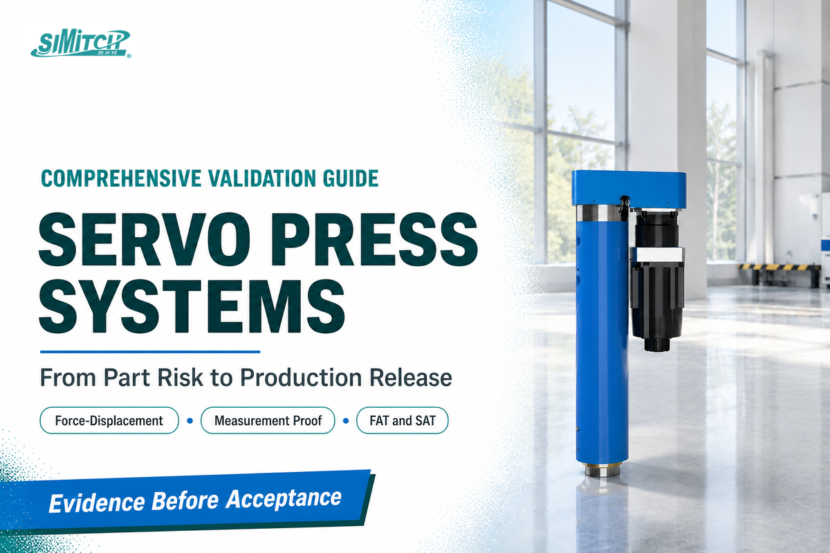
Servo press systems are electromechanical systems that command motion, measure force and position, and record a curve for every cycle. That still does not prove that the part is good, the measurement is capable, the machine is safe, or the process is ready for release. Those conclusions require a connected evidence chain.
This guide shows how to build that chain for electromechanical assembly and joining presses: define the part risk, specify observable evidence, divide the cycle into measurable phases, prove the measurement chain, challenge the acceptance rule, and control change after release. For SIMITCH configurations, published specifications, and commercial project discussion, use the Servo Press Systems solution page. This article deliberately does not repeat its model, capacity, configuration, or quotation content.
TL;DR
Treat a servo press as one part of a production evidence system. A defensible release links the physical joint requirement to a measurement, a documented decision rule, challenged samples, machine-safety validation, traceable data, and owned revalidation triggers. A repeatable curve is useful evidence, not an automatic quality verdict.
Scope note: “Servo press” can also describe servo-driven mechanical stamping or forming presses. Those machines may have different process physics, hazards, and regulatory duties. This guide covers the assembly/joining press class represented by the linked SIMITCH solution. Classify the actual machine before applying any safety or inspection requirement.
Quick Specs: Scope, Evidence, and Boundaries
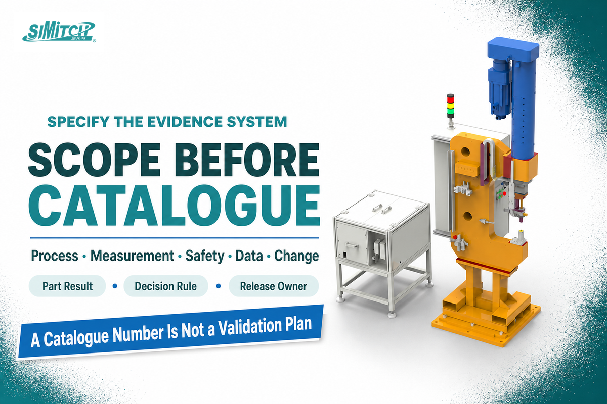
The practical specification is not a catalogue number. It is a controlled statement of what the joint must do, what failure looks like, what the press can observe, what independent check establishes the part result, and who can release or change the process.
Terminology boundary: how this guide uses common servo-press language
Search results use overlapping labels. An electric servo press, electric press, press machine, assembly press, joining module, or complete joining system may describe related but not identical scope. Many electromechanical joining systems use an electric motor, servo amplifier, and a ball screw or roller screw to convert rotary motion into linear motion. Depending on architecture, electric actuators move the press ram, while a load cell and position feedback provide force and displacement data for process monitoring systems.
Those components can support precise force control, position accuracy, contact point detection, and real-time monitoring during a press operation, but “precise control,” “high-precision,” and “high accuracy and repeatability” remain claims that need a declared test boundary. A machine builder must also distinguish direct force measurement from motor-current inference, and must define how the monitoring systems behave in the production environment.
Applications may span automotive and medical devices, while other searches concern sheet metal emboss work or other forming processes outside this assembly-process guide. Comparisons with pneumatic presses, hydraulic presses, or a traditional hydraulic press still require the actual force range, high forces, cycle, utilities, safety, maintenance, production efficiency, and total cost of ownership. A query such as “100 kN servo press” or “kN servo press” expresses commercial capacity intent; it does not supply a validated application requirement.
Kistler servo products, SCHMIDT ServoPress, and SCHMIDT Technology appear in competitor terminology. They are not SIMITCH claims or recommendations here. Whether a new servo press replaces an existing press, and whether a full servo approach is cost-effective, depends on the press tooling, assembly process, quality assurance, and quality control evidence. Servo presses include many configurations, so the press supplier still needs a project-specific process brief.
| Decision category | Evidence required | What it does not prove |
|---|---|---|
| Process fit | A signal that changes when the relevant defect changes | That servo is always the best drive |
| Force capacity | Real workpiece load at the required travel and duty | Part quality at nominal rating |
| Motion recipe | Phase, transition, limit, and fault-response definition | That every cycle produced a conforming joint |
| Calibration | Current result, uncertainty, traceability chain, and conditions | Production measurement capability |
| Curve window | Correlation, challenge results, and documented decision rule | A universal defect detector |
| Tooling baseline | Alignment, stiffness, revision, and approved load path | That the fixture cannot drift |
| Safety validation | Risk assessment plus validated safety functions and safeguards | That a quality pass makes access safe |
| Data record | Part, recipe, tool, time, result, and override identities | Traceability from a CSV checkbox alone |
| FAT/SAT release | Approved evidence pack and open-item disposition | Readiness from one successful cycle |
| Change approval | Impact classification and risk-based revalidation | Permanent validity of a golden curve |
What a Servo Press System Controls and What It Cannot Validate Alone

A servo press controls commanded movement and can relate measured force to position, time, or another signal. It cannot independently establish the physical condition of the joint, the competence of the measurement chain, or the adequacy of the machine safeguards.
In the automotive industry, assembly presses are often used where press force and position signatures can support in-station decisions. These systems are used only effectively when the press technology is matched to the joint mechanism and the independent quality requirement.
Think in four layers. The command layer asks whether the axis followed the requested phase. The measurement layer asks whether force and position values are trustworthy under the installed conditions. The part layer asks whether the assembly meets its functional requirement. The release layer asks whether the evidence and risks are acceptable for production.
This separation matters because two parts can produce similar peak force for different physical reasons. Conversely, normal material or lubrication variation can move a good part’s curve without changing its function. A system becomes useful for acceptance only after the measured signature has been correlated with independently verified part results. The NIST traceability guidance reinforces the same discipline on the measurement side: traceability belongs to a documented measurement result and its chain, not simply to the instrument name.
Decision rule: Never let “the axis reached the recipe” silently become “the part is conforming.” Record which evidence supports each conclusion.
Start with Part Risk: The 10-Field Part-to-Proof Specification Canvas
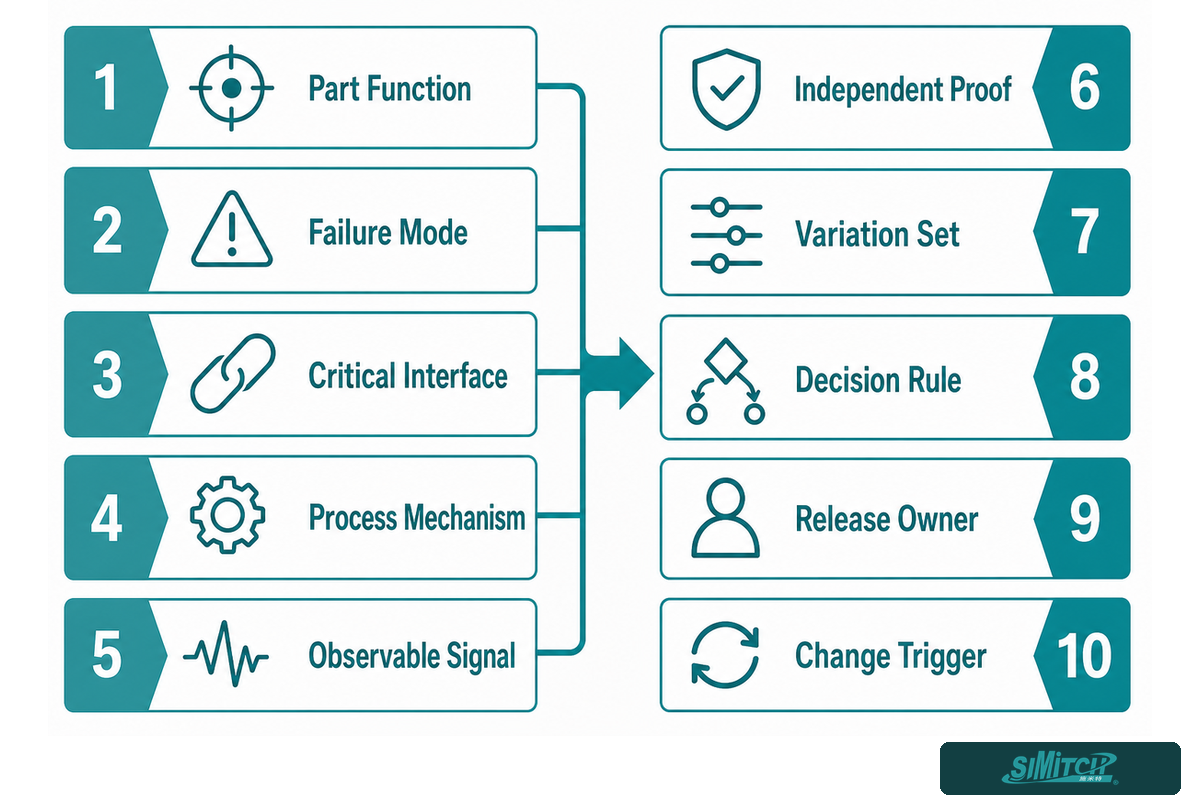
A strong pressing specification starts with the failure that matters to the finished assembly. It then works backward to the process signal and independent confirmation needed to detect that failure, before anyone selects nominal force or motion hardware.
Use the following canvas during design reviews. The row order is deliberate: function comes before equipment, and proof comes before acceptance limits.
| Canvas field | Question to answer | Controlled output |
|---|---|---|
| 1. Part function | What must the joined assembly do? | Functional requirement |
| 2. Failure mode | What can be missing, damaged, loose, cracked, tilted, or over-deformed? | Risk statement |
| 3. Critical interface | Which contact, fit, seat, or deformation creates the function? | Physical characteristic |
| 4. Process mechanism | What force-motion behavior creates that interface? | Phase hypothesis |
| 5. Observable signal | Which force, position, time, slope, or external signal should change? | Candidate feature |
| 6. Independent proof | How will the physical result be confirmed? | Inspection/test method |
| 7. Variation set | Which lots, temperatures, tools, alignments, and defect states matter? | Challenge population |
| 8. Decision rule | How are uncertainty and decision errors handled? | Acceptance logic |
| 9. Release owner | Who approves the rule and exceptions? | Signed responsibility |
| 10. Change trigger | Which changes can invalidate the relationship? | Revalidation rule |
The canvas does not calculate press capacity. It prevents premature sizing from hiding an undefined quality requirement. Its risk-first sequence follows the logic of ISO 12100 machinery risk assessment. Once the evidence fields are approved, engineering can translate peak and continuous load, usable travel, cycle profile, tooling, duty, environment, interfaces, and safeguards into a machine requirement.
When a Servo Press Is Not the Right Process Architecture
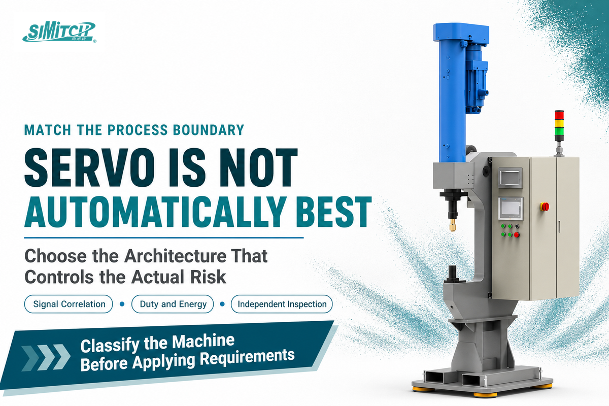
A servo press is a strong candidate when programmable phases and per-cycle signals change the release decision. With those evidence fields set, it may be the wrong investment when the measured signature does not correlate with the defect, another architecture meets the risk more simply, or the required process regime falls outside the practical system envelope.
Strong fit signals
- Different defects change an observable curve feature.
- Speed, position, force, or dwell must change by phase.
- Recipes vary by part and require controlled identity.
- Per-cycle evidence is part of the quality plan.
- Automation needs deterministic data and fault handshakes.
Review another route
- Good and bad parts cannot be separated by the available signal.
- The process chiefly needs a different force, energy, or long-stroke behavior.
- Added control does not change inspection or release.
- The environment or load path defeats the measurement concept.
- A simpler press plus independent inspection controls the risk.
Do not turn this into a universal servo-versus-hydraulic argument. Drive choice follows the process boundary, not a marketing adjective. Also classify the machine legally and technically: OSHA 1910.217 contains specific duties and explicit exclusions for mechanical power presses, so its schedules and PSDI provisions cannot be copied onto every assembly press.
Divide the Press Cycle into Measurable Phases
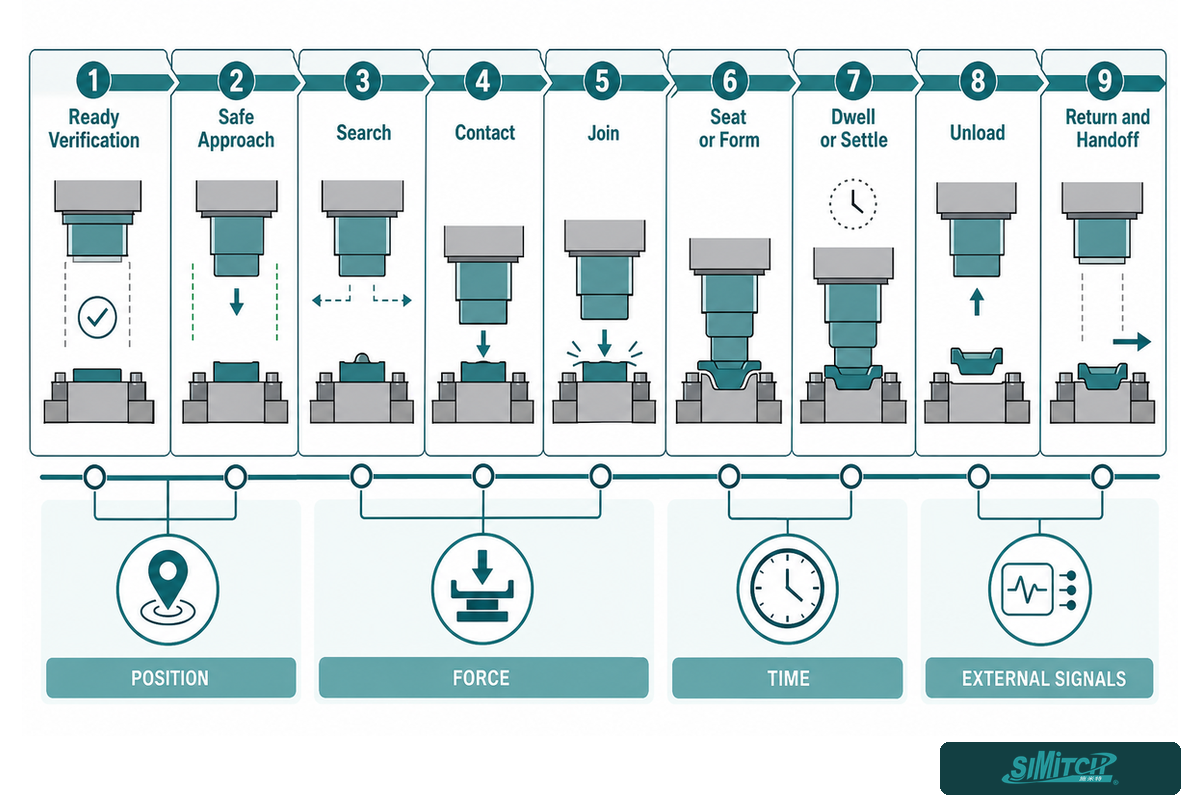
Build the recipe from workpiece behavior, not from one continuous motion command. Within that process boundary, each phase needs a control variable, a transition condition, a monitored signal, a timeout or limit, and a defined response when the expected event does not occur.
- Ready verification: confirm part, tool, recipe, permissives, and required data identities.
- Safe approach: move through free space under the machine’s validated motion and safety design.
- Search: reduce speed before expected contact and watch for early or missing contact.
- Contact: establish the reference event using a defined force, position, or external condition.
- Join: control the required force-motion relationship while monitoring the relevant features.
- Seat or form: evaluate the end condition without assuming peak force is sufficient.
- Dwell or settle: hold force or position only where the part mechanism requires it.
- Unload: observe relaxation or residual behavior if it carries information.
- Return and handoff: clear the station, finalize the record, and communicate disposition.
A phase can transition on position, force, time, slope, an external sensor, or a combination. The correct trigger is the one tied to the physical event; a press-fit monitoring patent record illustrates this broader signal vocabulary without establishing universal settings. A time-only transition may be stable in one process and blind in another. The same applies to fault logic: “did not contact by the expected region” and “contacted too early” are different failures and should not share an opaque generic alarm.
Read the Curve by Phase: The 6-Zone Press-Curve Diagnostic Grid
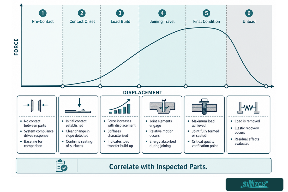
Interpret force-displacement data as a sequence of physical events. The six-zone grid below is an interpretation aid, not a universal curve template. Every candidate signature must be correlated with inspected parts and the actual load path.
| Zone | Candidate evidence | Possible questions | Cannot prove alone |
|---|---|---|---|
| 1. Pre-contact | Baseline and free travel | Sensor zero? Drag? Unexpected obstruction? | Part presence |
| 2. Contact onset | Contact position and initial rise | Wrong stack height? Early contact? Missing feature? | Correct orientation |
| 3. Load build | Slope and smoothness | Interference change? Misalignment? Surface condition? | Final joint function |
| 4. Joining travel | Force-position path and local events | Galling? Tilt? Geometry transition? Material variation? | Root cause without inspection |
| 5. Final condition | End position, force, work/area, seat behavior | Fully seated? Overloaded? Stopped on fixture? | Long-term retention |
| 6. Unload | Relaxation and residual position | Elastic recovery? Slip? Tool release issue? | Durability |
Research on precision press-fit assemblies supports using the press-fit curve and maximum force together, but its numerical results remain case-specific. Patent records also describe tolerance windows, slope, speed, and external comparison signals. Those sources support a broader curve-reading vocabulary; they do not turn any one signature into a universal defect code.
Prove the Measurement Chain Before You Trust the Window
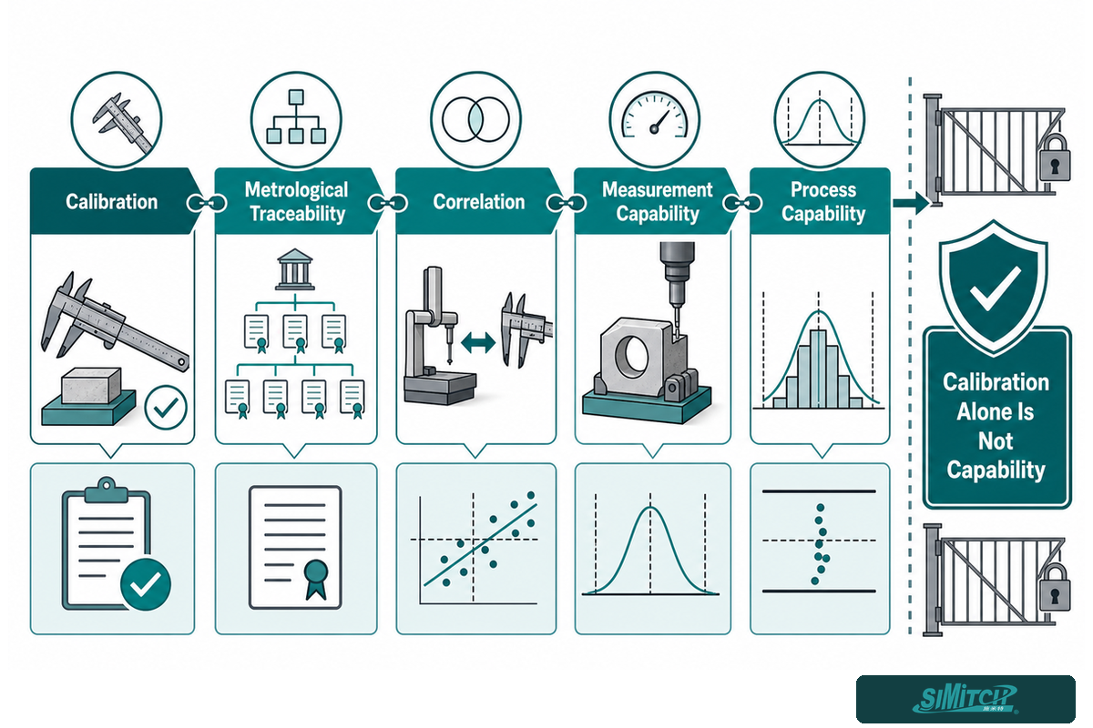
Calibration, metrological traceability, correlation, measurement capability, and process capability answer different questions. Applied to the six-zone grid, a current calibration result is necessary evidence, but it does not prove that the installed production system can discriminate a narrow acceptance band.
- Calibration compares an instrument or system with a reference under stated conditions.
- Metrological traceability connects a measurement result to a reference through a documented unbroken chain, with each calibration contributing uncertainty.
- Correlation checks whether the installed press signal agrees sufficiently with an independent reference or part-result method for the intended use.
- Measurement capability evaluates variation, bias, stability, linearity, resolution, fixtures, operators/automation, and the intended tolerance.
- Process capability evaluates the process distribution after measurement adequacy has been established.
NIST notes that measurement uncertainty can cause good product to fail and faulty product to pass. ASQ’s GR&R overview similarly separates repeatability, reproducibility, and part-to-part variation. Use the method appropriate to the actual automatic system; do not copy a sample count or percentage without a risk and study rationale.
Check the chain across the intended operating range, not only at one convenient point. Record the reference, uncertainty, installed fixture and load path, sensor location, signal conditioning, scaling, filtering, sampling behavior, software revision, environmental condition, time basis, and result identity.
Challenge the Limits: The 9-Step Acceptance-Window Challenge Protocol
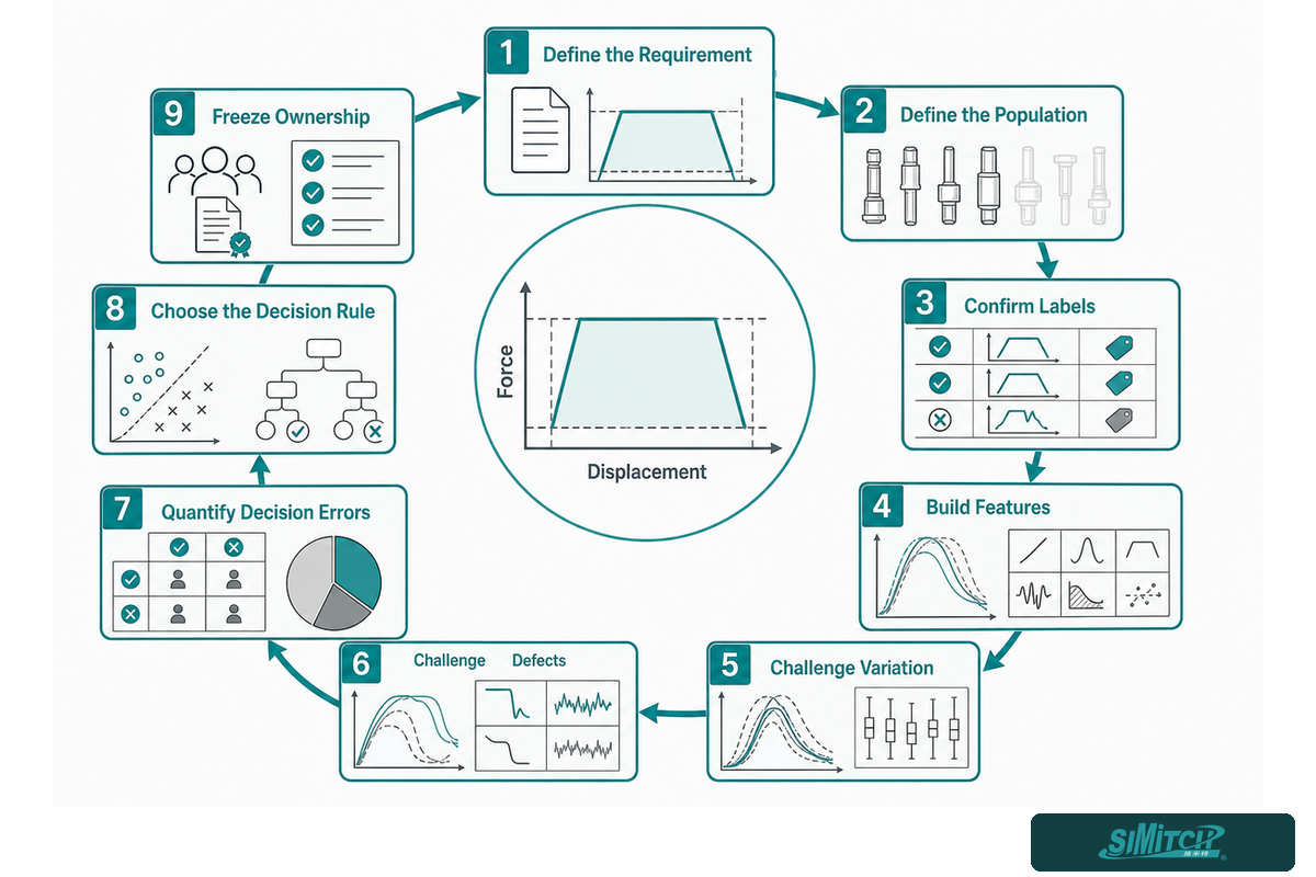
An acceptance window is credible only when it is tied to independently confirmed part results and a documented conformity decision. Known-good curves define a starting region; they do not prove that the rule catches realistic defects or handles measurement uncertainty.
- Define the requirement: state the physical or functional characteristic and its approved limit.
- Define the population: include intended products, lots, tools, shifts, environments, and startup states.
- Confirm labels: establish good, boundary, and defective conditions using an independent method.
- Build features: test phase-aware indicators rather than relying on one maximum value.
- Challenge variation: include material, lubrication, alignment, tool condition, temperature, and reasonable setup variation.
- Challenge defects: use safe, controlled, known defect states that represent real failure mechanisms.
- Quantify decision errors: record false accepts and false rejects, including uncertainty near limits.
- Choose the decision rule: document any guard band, acceptance zone, escalation zone, and sampling rationale.
- Freeze ownership: approve the rule, exception process, and revalidation triggers.
The NIST conformity-assessment discussion distinguishes the technical evaluation of uncertainty from the business decision rule used to balance accepting nonconforming product and rejecting conforming product. That is why a challenged curve population, while essential, is not enough by itself.
Illustrative worksheet only – not machine settings or acceptance limits
The hypothetical values below show how units and conditions should be declared. They are not SIMITCH specifications, empirical results, or transferable limits.
| Declared item | Hypothetical development input | Question |
|---|---|---|
| Reference travel | 25.0 mm | Is installed position correlated across the range? |
| Expected contact region | 7.8 mm to 8.2 mm | Do boundary parts remain distinguishable? |
| Development force region | 4.8 kN to 5.2 kN | Does the independent part result agree? |
| Approach speed | 20 mm/s | Is the contact transition safely controlled? |
| Joining speed | 1.2 mm/s | Does speed change the curve or part result? |
| Dwell comparison | 0.4 s and 0.8 s | Is dwell physically necessary? |
| Reference force checks | 1 kN, 3 kN, and 5 kN | Are bias and uncertainty acceptable? |
| Reference position checks | 5 mm, 15 mm, and 25 mm | Is scaling stable through usable travel? |
| Temperature states | 18 °C, 23 °C, and 30 °C | Does the part or measurement shift? |
| Early-contact challenge | 0.3 mm offset | Does the rule detect the intended mechanism? |
| Force-reference uncertainty | ±0.02 kN | How does it affect the decision boundary? |
| Position-reference uncertainty | ±0.01 mm | Is a guard band or escalation zone needed? |
| Low-force challenges | 0.1 kN, 0.2 kN, and 0.4 kN | Does resolution support the decision? |
| Travel challenges | 2 mm, 4 mm, and 6 mm | Can scaling or fixture shift be separated? |
| Time challenges | 0.2 s, 0.5 s, and 1.0 s | Does the physical mechanism depend on time? |
| Speed challenges | 10 mm/s, 20 mm/s, and 40 mm/s | Does dynamics change the observed signature? |
| Additional speed points | 50 mm/s, 60 mm/s, 70 mm/s, 80 mm/s, and 90 mm/s | Which points are actually needed for the study range? |
Treat Tooling, Frame, and Load Path as Part of the Measurement System
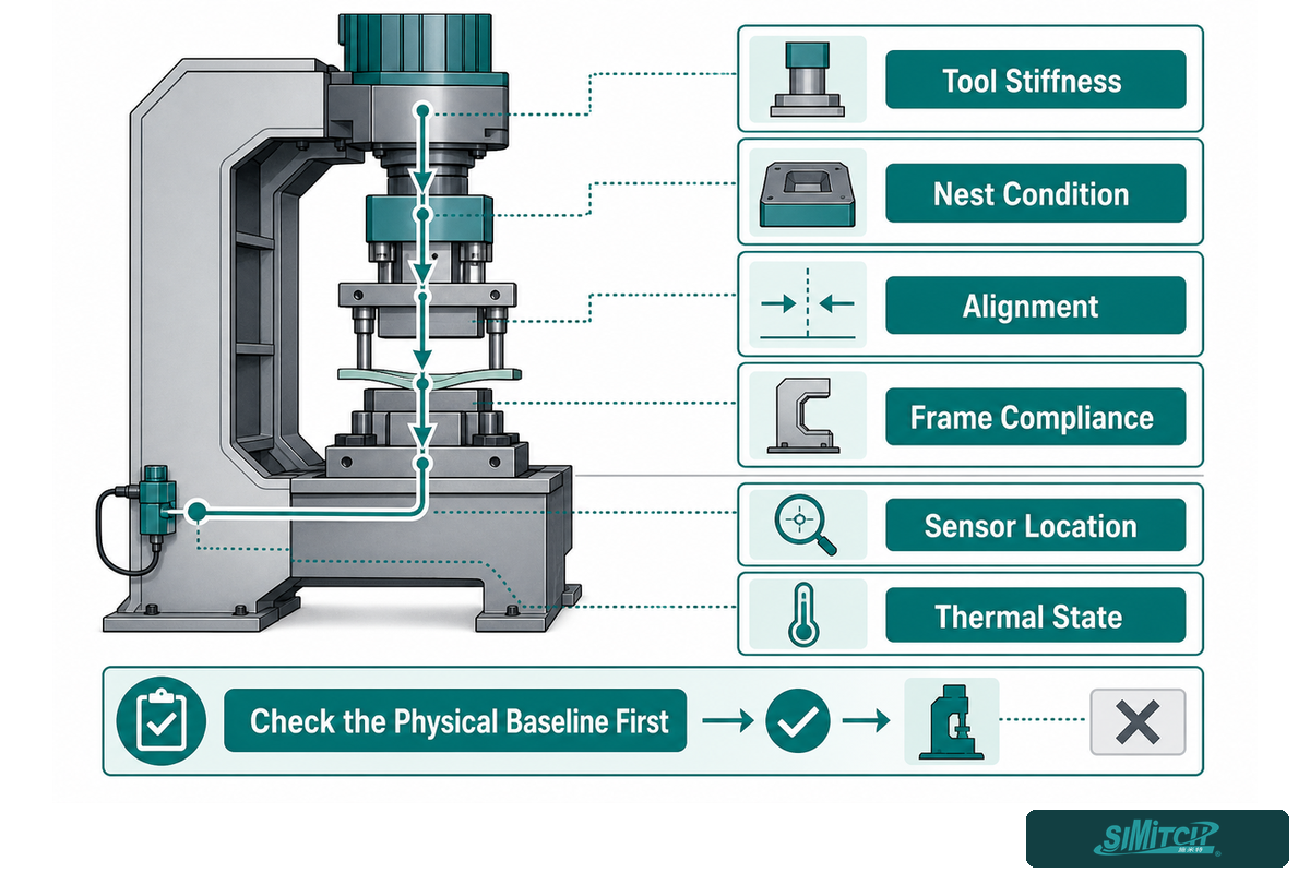
The recorded curve belongs to the complete installed load path, not just the part. Within the challenged acceptance window, tool stiffness, nest condition, alignment, frame compliance, sensor location, and thermal state can change what the controller observes.
When a curve shifts, inspect the physical transfer path before editing the recipe. A precision press-fit assembly study likewise treats module calibration, alignment and perpendicularity as part of measurement credibility. Look for loose or revised nests, off-axis contact, wear, debris, damaged locating features, tool-stack changes, fastener movement, frame or table deflection, sensor mounting changes, lubrication changes, and maintenance work. A recipe adjustment that masks a mechanical change can restore a green screen while weakening the connection between the signal and the part result.
First response to curve drift: contain affected product, compare the physical baseline, verify measurement references, then decide whether a recipe change is justified. Do not tune around an unknown cause.
Integrate Data Governance and Machine Safety Without Mixing Their Roles
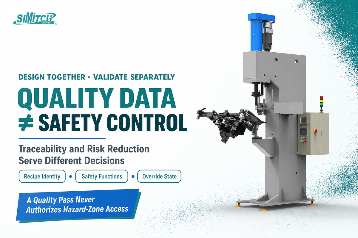
Quality data and safety controls should be designed together because they share machine states and interfaces, but they serve different decisions. Beyond the physical load-path baseline, a quality “pass” cannot authorize entry into a hazard zone, and a safety circuit does not prove the joint is conforming.
At minimum, associate each retained process result with the part, carrier, or lot identity; recipe revision; tool revision; timestamp and time basis; force-position record or extracted features; decision code; fault state; override state; and software/configuration revision. Define what happens if the MES, line PLC, or storage layer is unavailable. “File exported” is not the same as traceable data if identity, sequence, revision, or ownership is missing.
For safety, ISO 12100:2010 provides machinery risk-assessment and risk-reduction principles. ISO 13849-1:2023 covers design and integration of safety-related control parts, while ISO 13849-2:2012 separately addresses validation by analysis and testing. In covered U.S. workplaces, OSHA’s general machine-guarding rule requires protection from point-of-operation and other hazards.
“One or more methods of machine guarding shall be provided”
Actual safeguard selection, required performance level, validation evidence, inspection schedule, and legal applicability belong to the machine-level project. Verify the current edition and local jurisdiction. Do not use this guide as a safeguarding design instruction.
Release the Process with the 8-Evidence Production Release Pack
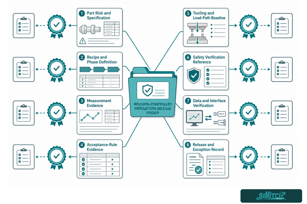
FAT and SAT should release a defined evidence package, not merely demonstrate that the ram cycles. With the data and safety boundaries kept distinct, the package must show why the process should make an acceptable part and how the installed system will detect, contain, and document relevant deviations.
- Part-risk and specification record: approved functions, failure modes, limits, and proof methods.
- Recipe and phase definition: commands, transitions, monitored features, limits, and fault responses.
- Measurement evidence: calibration, traceability, uncertainty, installed correlation, and capability.
- Acceptance-rule evidence: labelled populations, challenge results, decision rule, and sampling rationale.
- Tooling/load-path baseline: revision, alignment, fasteners, stack, references, and approved condition.
- Safety verification reference: risk-assessment disposition, safety-function validation, and safeguard checks.
- Data and interface verification: identities, time basis, result storage, faults, overrides, and recovery behavior.
- Release and exception record: owners, open items, concessions, containment, revalidation triggers, and approval.
FAT can establish the evidence structure and verify functions under supplier-site conditions; where safety-related control parts are in scope, ISO 13849-2 separately addresses validation by analysis and testing. SAT should confirm the package with the installed utilities, actual tooling, production interfaces, local environment, upstream/downstream equipment, approved products, and site safety controls. If an item cannot be completed, record the risk, containment, owner, due date, and authority for conditional release.
Keep the Recipe Valid with the Recipe Drift Control Loop
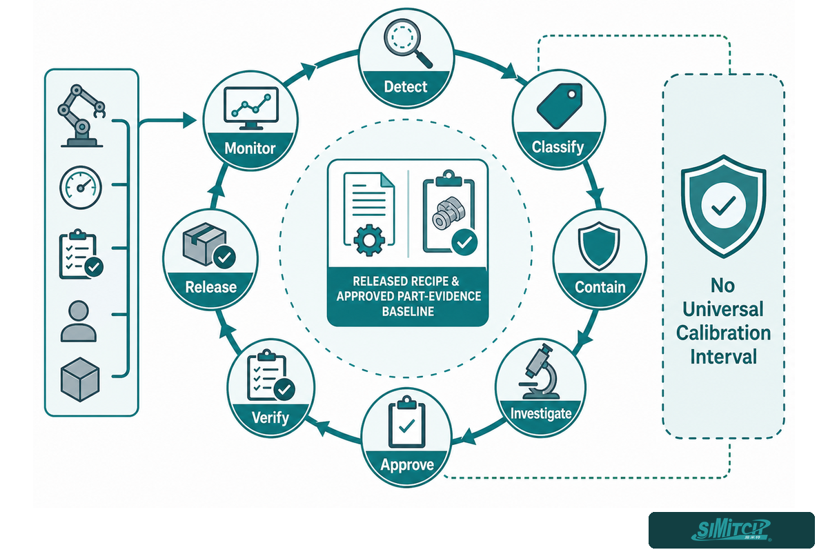
Production validation expires when an uncontrolled change breaks the relationship between part result and process evidence. The Recipe Drift Control Loop makes change detection, containment, investigation, approval, verification, and monitoring part of normal ownership.
Detect → classify → contain → investigate → approve → verify → release → monitor. Apply the loop to recipe edits, force or position scaling, sensor replacement, calibration outcomes, tooling revision, fixture repair, product/material change, lubrication change, software/firmware update, data-filter change, machine relocation, structural maintenance, or a sustained curve shift.
There is no single engineering interval that fits every servo press measurement chain. NIST calibration guidance assigns interval setting to the organization based on application-specific factors. Set calibration and intermediate-check intervals from risk, use, environment, manufacturer guidance, drift history, measurement assurance, and the quality system. However, that general statement never overrides a fixed inspection, test, or revalidation frequency imposed by an applicable regulation, standard, customer requirement, or validated maintenance plan.
Preserve the released baseline, but do not treat it as permanent. Trend the features that matter, review false rejects and escapes, and make sure a change cannot enter production through an undocumented “small adjustment.”
Frequently Asked Questions
What is a servo press used for?
A servo press is used for controlled assembly and joining operations such as press-fitting, inserting, staking, crimping, riveting, or forming where programmable motion and force-position evidence can improve process control. The useful application is not defined by the servo motor alone. The measured signature must relate to the actual part requirement, and the installed system still needs tooling, measurement, safety, data, and release evidence appropriate to the project.
What is the difference between a mechanical press and a servo press?
The practical difference is the motion and feedback architecture, not a universal claim that one is more precise or efficient. An electromechanical assembly servo press can program phases and record force-position evidence per cycle. A conventional mechanical press often follows motion defined by its drive mechanism, while a servo-driven mechanical forming press is another distinct class. Compare the actual process force, energy, stroke, speed, duty, tooling, safety, and evidence needs before choosing.
How do you size a servo press system?
Start with the real process load at the required position, usable travel, approach/join/return profile, speed and dwell, continuous versus peak duty, tooling and load path, environment, interfaces, measurement evidence, and installed-machine safety needs. Nominal force alone is not enough, and the required usable work region matters as much as a headline rating. After the process brief is approved, review the published SIMITCH configurations or discuss the application boundary with the supplier.
How often does a servo press need calibration?
There is no universal interval. Set it from risk, use, environment, manufacturer guidance, drift history, intermediate checks, and applicable fixed regulatory or customer requirements.
Can a servo press replace a hydraulic press?
It can replace a hydraulic press in some applications, but only after the real force, stroke, energy, motion profile, duty, cycle, environment, footprint, utilities, safety, measurement, maintenance, and lifecycle requirements are compared. The review should also include existing tooling, operator interaction, spare-parts strategy, controls competence, data retention, and how each architecture handles abnormal parts. If programmable phases and per-cycle evidence change the quality decision, servo control may add value. If another architecture meets the physical and evidence requirements more simply, replacement may not be justified.
What cycle time can a servo press achieve?
Cycle time is application-specific. It includes safe approach, contact search, joining motion, dwell or settle time, unloading, return, part handling, safety interlocks, station communication, data finalization, and any external inspection. A fast axis cannot remove physical dwell or line-handling requirements. Ask for a cycle study using the actual part, tool, motion profile, interfaces, and release logic rather than accepting one universal number.
From a Good Curve to a Controlled Production Process
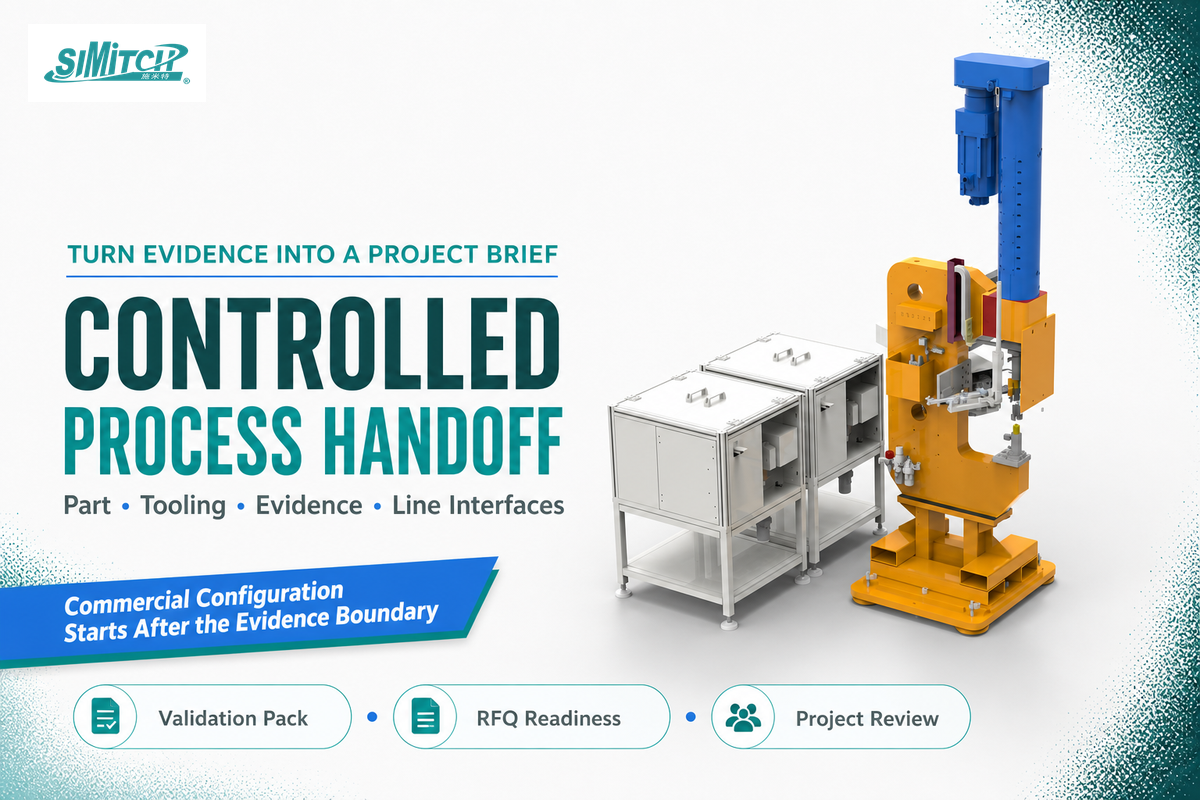
A useful servo press validation path is simple to state and disciplined to execute: define the part risk, translate it into observable evidence, program the cycle by physical phase, prove the measurement chain, challenge the decision rule, release an auditable FAT/SAT evidence pack, and control every change that could invalidate the relationship.
If your next step is commercial configuration, capacity review, or integration discussion, review SIMITCH Servo Press Systems and published configurations. Use the servo press RFQ readiness checklist to organize the part, process, tooling, evidence, and line-interface requirements. You can also learn about SIMITCH’s machinery and integration background before a project review.
Discuss Your Servo Press Application
Editorial transparency: This guide is informational support content. The five named frameworks are original planning tools, not standards. Numerical worksheet values are hypothetical. Safety, conformity, calibration, sampling, and release decisions require project-specific engineering and applicable local requirements.
References and Sources
- ISO 12100:2010 – Safety of machinery, risk assessment and risk reduction
- ISO 13849-1:2023 – Safety-related parts of control systems, design principles
- ISO 13849-2:2012 – Safety-related parts of control systems, validation
- OSHA 29 CFR 1910.212 – General requirements for all machines
- OSHA 29 CFR 1910.217 – Mechanical power presses
- NIST – Metrological Traceability
- NIST – Metrology and Process Control: Dealing with Measurement Uncertainty
- NIST – Assessment of Conformity, Decision Rules and Risk Analysis
- ASQ – Gage Repeatability and Reproducibility
- Prediction of Pressing Quality for Press-Fit Assembly Based on Press-Fit Curve and Maximum Press-Mounting Force
- Automatic press-fit assembly of small precision interference fitting parts