Get in touch with Suzhou Simitch Machinery Co., Ltd Company

A robotic assembly line is, in this guide, the robot-centered portion of production: one defined assembly task, its tool, part state, reachable path, measurable result, and recoverable fault sequence. The scope stays at robot-task fit and cell evidence.
In modern production, engineering, quality, operations, and procurement teams can use it to qualify the task, compare structures, define end-effector and process interfaces, and plan cell-level evidence. Modern assembly lines may connect many such cells, but this is not a design manual for an automated production line; whole-line takt, buffers, shared transfer, station balancing, and plant-level acceptance remain with the separate automated-line guide.
Updated August 2026 · By XCX
A practical design sequence
| Qualify the task | Incoming part state, work content, access, required result, exceptions, and recovery |
| Choose the architecture | Robot structure, operating mode, fixed equipment, tooling, feeding, and sensing |
| Own the interfaces | Datum, recipe, signal, result, abnormal condition, response, and retained evidence |
| Validate the application | Repeated representative trials, faults, changeovers, statistics, and evidence owners |
Define Robotic Assembly Tasks Before the Line
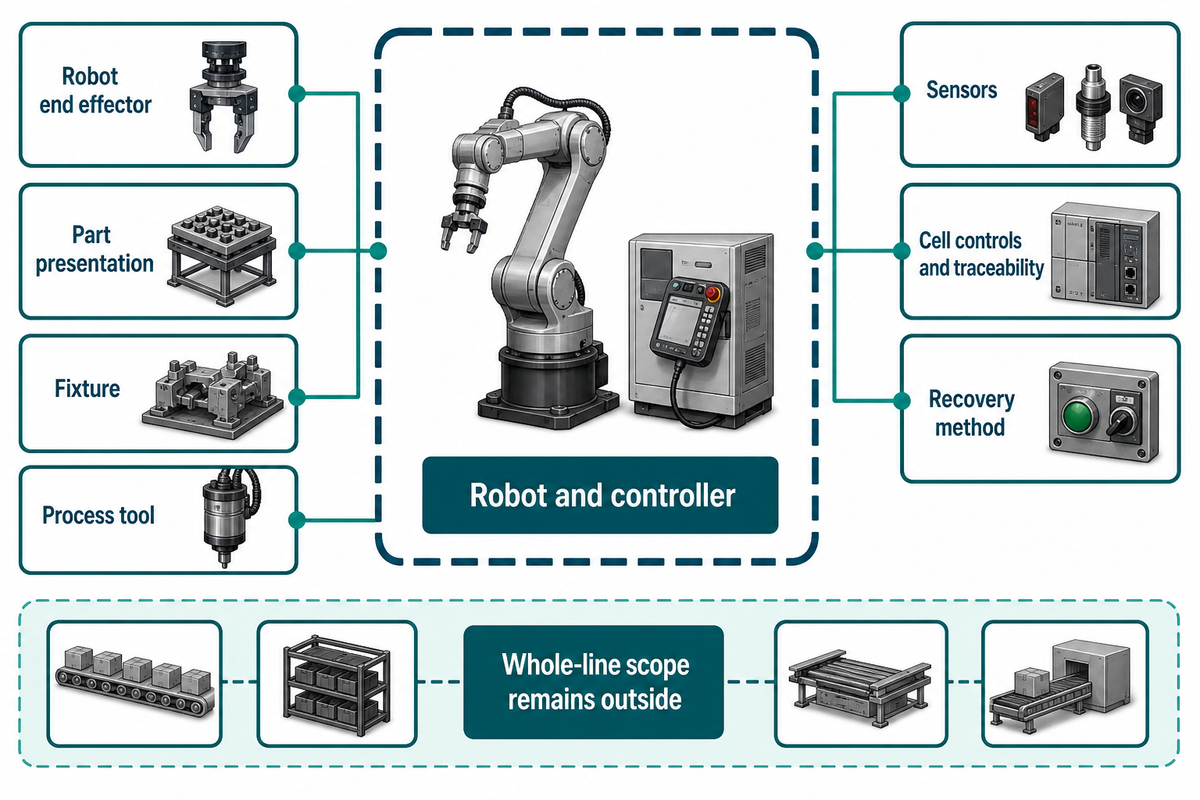
For this guide, the system means the machine-centered portion of production: one or more product-changing tasks plus the tooling, part presentation, sensing, controls, and recovery needed to prove those tasks. It does not claim ownership of upstream balance, buffers, shared transfer, or whole-line acceptance.
The system boundary normally includes the robot and controller, robot end effector, part presentation, fixture, process tool, sensors, safeguarding interfaces, cell controls, traceability, and recovery method. The OSHA robot-systems chapter similarly treats the application as more than the arm: tooling, controls, sensing, communication, safeguarding, and fixtures belong to the completed application.
The useful question is not “Where can we place a robot?” It is “Which repeatable assembly result can the complete cell create, verify, and recover?”
That boundary keeps this guide separate from broader line design. The related line-level balancing and transfer guide covers takt, buffers, shared transfer, station interfaces, and whole-line acceptance; this article stays with robot-task fit, tooling, part state, motion, sensing, joining, and cell evidence.
Start With the Assembly Process, Not the Robot
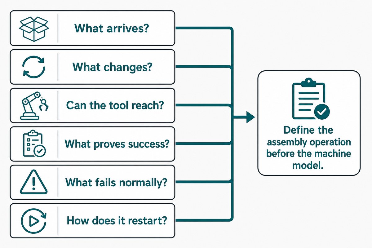
Assembly tasks are ready for automation when their incoming part state, repeatable work, access path, required process result, exception route, and recovery evidence can be described before a machine model is chosen. Repetition at the operator level is not enough if the part, fixture, or abnormal condition remains uncontrolled.
For assembly applications, break the work into observable steps: pick, orient, locate, clamp, insert, fasten, join, dispense, inspect, release, and handle a failed result. A peer-reviewed human-robot task-allocation study found that the better allocation depends on process delays and available parallelism, so it cannot justify a universal cobot choice.
| Question | Ready evidence | Reason to pause |
|---|---|---|
| What arrives? | Known orientation, identity, tolerance, and cleanliness | Random overlap, hidden damage, or unstable presentation |
| What changes? | Defined assembly operation and sequence | Operator judgment supplies missing process knowledge |
| Can the tool reach? | Access, approach, clearance, and reaction path | Frequent hand fitting or uncontrolled obstruction |
| What proves success? | Measurable process or inspection result | Only a robot-complete signal is available |
| What fails normally? | Named faults and part disposition | Exceptions depend on improvisation |
| How does it restart? | Known state, owner, access, and evidence continuity | Alarm reset is the entire recovery plan |
Parts feeding often decides whether assembly line automation is practical enough to automate production reliably. Feedall’s flexible-feeding discussion shows why product variation, changeover burden, presentation reliability, gripper complexity, and required throughput must be weighed rather than assuming one universal feeder.
Robotic assembly line examples are useful only when they disclose part variation, tooling, faults, and acceptance conditions. Search results about robots for assembly, including “assembly robots examples” or “robotic adhesive dispensing systems,” are only starting points; buyers should use the same evidence boundary instead of ranking polished demonstrations.
Separate Robot Types, Collaborative Operation and Fixed Equipment
Choose on three separate axes: machine structure, collaborative or non-collaborative operating mode, and the fixed equipment that presents, constrains, processes, or transfers the part. They are not mutually exclusive categories; one cell may combine a SCARA robot, a collaborative phase, a feeder, a fixture, and a conveyor system.
Six-axis articulated robots offer broad orientation freedom, while SCARA robots suit selected planar motions and delta robots favor particular high-speed handling patterns. These types of robots, and the robot types within them, still require application evidence; structure labels do not establish payload fit, safety strategy, precision at the tool, or process capability by themselves.
| Axis | Examples | Decision inputs | Common confusion |
|---|---|---|---|
| Robot structure | Six-axis, SCARA, delta | Reach, orientation, load, workspace, path | Treating a structure as a complete application |
| Operating mode | Collaborative or non-collaborative application | Human interaction, task, speed, force, separation, assessment | Assuming a cobot label removes application assessment |
| Supporting equipment | Feeder, fixture, press, process machine, conveyor | Presentation, datum, reaction load, transfer, recovery | Treating fixed automation as the opposite of robotics |
How do I know if my production line is cobot-ready?
Collaborative operation is plausible when the task genuinely benefits from planned human interaction and the load, speed, workspace, tooling, part edges, stored energy, and failure behavior can be assessed as a complete application. Traditional robots behind safeguarding may still be the clearer route for high energy, high speed, long reach, or processes that do not need regular human proximity.
The current Association for Advancing Automation overview of ISO 10218 explains that the 2025 revision incorporates collaborative-application material while emphasizing the complete robot application. OSHA’s older public taxonomy is used here only to separate terms; the project must use applicable current requirements and its own task-based assessment.
Size Robot Motion Beyond Rated Payload
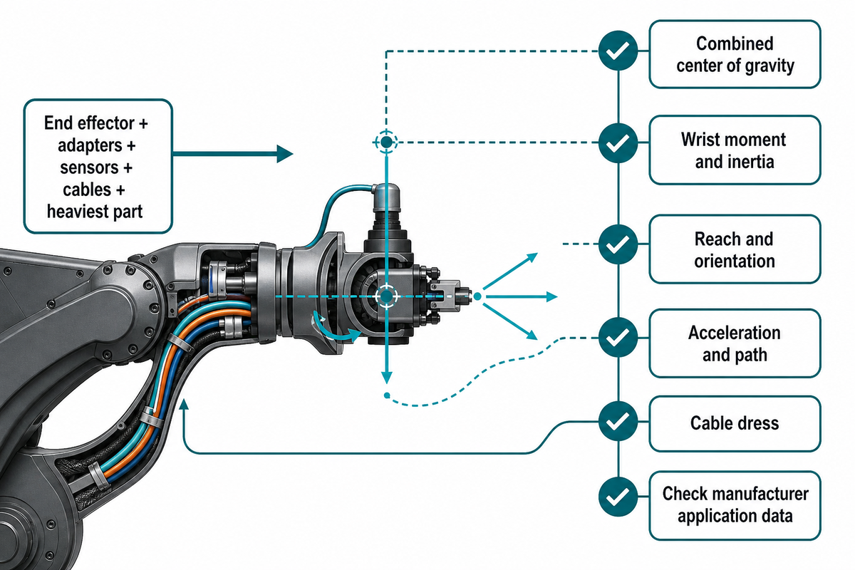
Robot sizing must combine end-effector mass, part mass, center of gravity, wrist moment, inertia, reach, orientation, approach path, cable dress, and attainable motion. Whatever structure or operating mode is chosen, a robot arm can satisfy the headline payload and still fail at the actual tool center point because the load is offset or the required pose lies at an unfavorable edge of the workspace.
The NIST performance-measurement report is a useful reminder that robot performance needs defined characteristics and measurement conditions. Catalog values are screening inputs, not production evidence for a selected robot, tool, part, path, and controller configuration.
Symbolic load stack
Total carried mass = end effector + adapters + sensors + cables carried by the wrist + heaviest part
Then check the combined center of gravity, wrist moment, inertia, reach, orientation, acceleration, and path against the selected manufacturer’s application data. This is a dependency checklist, not a universal sizing formula or safety margin.
Verify access in the real fixture, including approach, withdrawal, fastener feed, inspection view, maintenance clearance, and collision recovery. Modern assembly robots offer broad robotic capabilities, but modern robots do not remove the need for compliance, sensing, datum control, or tool design. Complex assembly, delicate assembly, and intricate assembly may depend more on those controls than on sophisticated robots.
Close the Robotic Assembly Task Evidence Loop
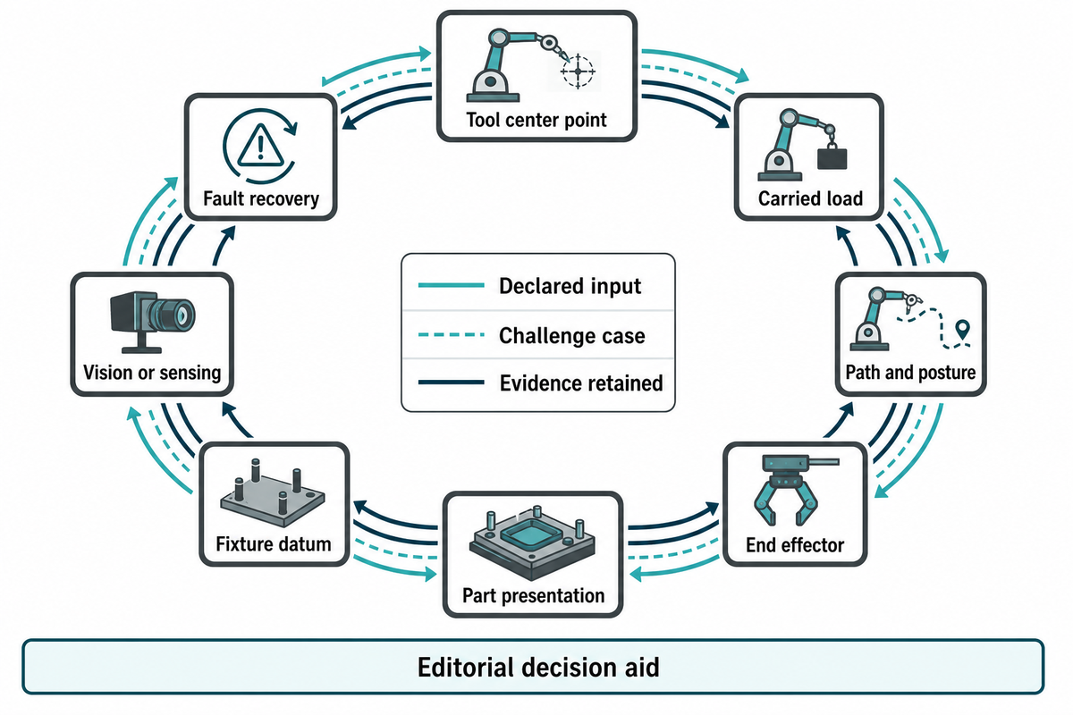
The Robot Task Evidence Loop connects the part state, tool center point, carried load, path, end effector, sensing, process result, and recovery state. A robot task is reviewable only when each checkpoint has a declared input, a challenge case, and retained evidence.
Advanced vision systems and sensors can reduce hard-fixture dependence, but they introduce their own lighting, calibration, processing, communication, and maintenance dependencies. In modern assembly, the way robots use vision data must be defined together with calibration and fault response; sensing should solve a known variation problem, not compensate indefinitely for unstable upstream handling. The NIST assembly performance work provides an external measurement basis for retaining repeatable task evidence.
Use the 8-Checkpoint Robot Task Evidence Loop
| Robot-task checkpoint | Declared input | Challenge case | Evidence retained |
|---|---|---|---|
| Tool center point | Frame, orientation, calibration method | Tool change or calibration drift | Frame version and verification result |
| Carried load | Tool, adapters, sensors, cables, part, center of gravity, inertia | Heaviest part at unfavorable posture | Load declaration and sizing check |
| Path and posture | Approach, working pose, withdrawal, clearance | Worst-case variant and cable position | Reviewed path and collision case |
| End effector | Grip, compliance, tool interface, utilities | Wear, part tolerance, lost grip | Tool state and maintenance limit |
| Part presentation | Orientation, separation, identity, cleanliness | Doubled, wrong, damaged, or missing part | Detection and re-presentation result |
| Fixture datum | Location, constraint, clamp and reaction path | Not seated or clamp incomplete | Datum check and part disposition |
| Vision or sensing | Feature, lighting, calibration, confidence rule | Reflective, shifted, borderline, or no-read part | Challenge image, decision and calibration state |
| Fault recovery | Known part, robot, tool, recipe and sequence state | Interrupted motion or human access | State reconciliation and restart test |
A robot can pass a dry motion test while the task still fails at the tool, part, datum, sensing, or recovery checkpoint. The method above is editorial synthesis from public evidence; it isn’t a patented or proprietary Simitch technology and doesn’t claim a guaranteed production outcome.
Integrate Robotic Assembly Automation Without Losing Process Evidence
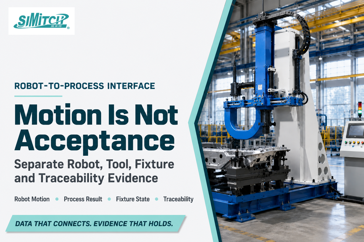
Separate robot motion from process success. Applying the dependency-chain logic, robotic assembly automation must define tool access, reaction path, process controller, recipe ownership, start permission, completion status, acceptance signal, failed-part route, and traceability record as connected but distinct interfaces.
The robot-complete bit proves that a programmed motion or handshake ended; it doesn’t by itself prove that a weld, fastener, press operation, rivet, or clinched joint met its acceptance condition. In automated robotic assembly, the process controller and quality method must own the result that matters to the product; the same rule applies when engineers separate press feedback from robot motion.
| Layer | Responsible evidence | Do not substitute |
|---|---|---|
| Robot motion | Pose, path, speed state, interlock, program and frame version | Robot-complete for joint acceptance |
| Process tool | Recipe, measured variables, result code, tool condition | Tool-ready for process result |
| Fixture and reaction | Part seated, clamp state, reaction load path | Clamp command for confirmed datum |
| Traceability | Part identity, recipe, result, timestamp, disposition | A disconnected inspection record |
The public scope of ISO 10218-2:2025 covers integration of industrial robot applications and cells but excludes hazards arising from processing materials, including metal. Robot-application safety therefore doesn’t replace the applicable task-based assessment for joining hazards, tooling, stored energy, workpieces, and fasteners.
According to company information supplied for this guide, Simitch focuses on hydro-pneumatic boosters, precision servo pressing, and lightweight sheet-metal joining technologies including Clinching, Riveting, SPAC, and SPR. Buyers defining a robot-to-process handshake can review robot-to-riveting handshake evidence; no unprovided accuracy, force, cycle-time, capacity, certification, or customer-result claim is made here.
The Simitch overview of where riveting-process ownership begins provides the adjacent equipment-family boundary. That resource owns product-family detail; this article uses it only to separate robot motion from process control and result evidence.
Define the joining boundary before comparing equipment
Bring the part stack, datum, access, reaction path, required result, traceability, failure route, and representative acceptance parts.
Commission and Validate the Robotic Cell Before Production Acceptance
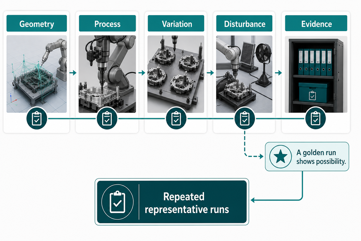
Acceptance should move from model to representative evidence. Those joining interfaces then guide layout and reach review, offline simulation, dry-cycle checks, process trials, repeated representative runs, injected faults, changeovers, recovery, and retained records. A golden run shows possibility, not the distribution of production behavior.
The NIST assembly performance metrics page says multiple task repetitions are required for benchmarking and points to tests of correlation, distribution, variance, and mean. It isn’t a factory-acceptance standard; this guide borrows only the measurement principle and requires each project to define its own sample plan, thresholds, and decision rules.
1. Geometry
Reach, clearance, fixture, tool, cable, and maintenance access
Reach, clearance, fixture, tool, cable, and maintenance access
2. Process
Representative parts, recipes, results, and measurement method
Representative parts, recipes, results, and measurement method
3. Variation
Part families, tolerances, presentation, changeover, and environment
Part families, tolerances, presentation, changeover, and environment
4. Disturbance
Feeder faults, no-read, tool fault, stop, restart, and part disposition
Feeder faults, no-read, tool fault, stop, restart, and part disposition
5. Evidence
Sample plan, distributions, variance, mean, thresholds, witness, and owner
Sample plan, distributions, variance, mean, thresholds, witness, and owner
Determine who owns each dataset and decision: integrator, process-equipment supplier, quality, production, maintenance, or buyer engineering. Manufacturing execution systems may receive selected records, but a software connection doesn’t prove that the measurement method, part identity, recipe, and disposition are correct.
Factory and site tests should use documented conditions and named exclusions. If production material, gauges, utilities, upstream feeding, or downstream handling aren’t available, record the limitation and what specific evidence is still required after installation.
Plan Robot Recovery Before the First Mid-Shift Stop
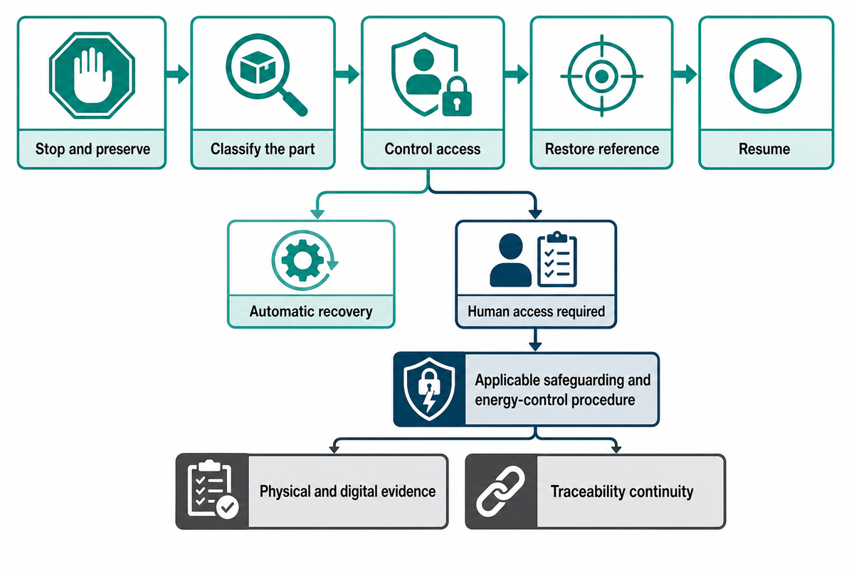
Recovery must restore a known physical part state, digital sequence, recipe, reference frame, and evidence trail. The validation plan should separate automatic recovery from any intervention that requires a person to enter, clear a jam, service a tool, or release stored energy.
The CDC and NIOSH hazardous-energy guidance identifies servicing, repair, and jam clearing as injury scenarios involving unexpected energization. It also lists electrical, mechanical, hydraulic, pneumatic, chemical, thermal, and other energy sources, so a general stop command isn’t automatically an adequate isolation method.
| Decision | Required answer | Evidence |
|---|---|---|
| Stop and preserve | What moved, what did not, and which record is open? | Fault, state, position, part and recipe snapshot |
| Classify the part | Unprocessed, partial, conforming, suspect, or rejected? | Disposition rule and physical containment |
| Control access | Can recovery stay automatic, or is human access required? | Applicable safeguarding and energy-control procedure |
| Restore reference | Which datum, frame, tool and recipe must be verified? | Check result and authorized reset owner |
| Resume | Where does sequence restart without repeating or skipping work? | Restart trial and traceability continuity |
What happens if the robot messes up mid-shift?
Stop in a controlled state, preserve available physical and digital evidence, classify the part, and determine whether human access requires energy isolation. Whether the design has a single robot, several robots and conveyor equipment, or broader robotic arm assembly lines, correct the cause, verify reference and recipe state, then resume without advancing an incomplete part.
Know When Not to Automate Assembly Tasks
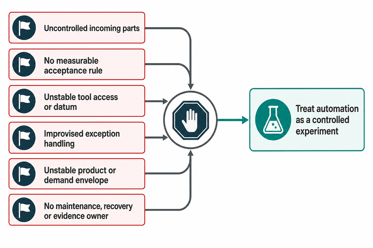
Postpone or reject robotic automation when incoming variation is uncontrolled, work is too infrequent, product life is uncertain, access changes continually, exceptions dominate, or the required result cannot be measured. A machine purchase cannot stabilize an assembly process whose inputs and acceptance conditions are still unknown. Transforming assembly is justified only when the selected task and evidence boundary support it.
Manual assembly may remain appropriate for very low frequency, judgment-heavy work or a product that is still changing. Fixed automation may be the stronger route for stable, constrained, high-rate work; flexible assembly may justify robots when product variation and changeover value outweigh additional sensing, programming, and recovery burden.
Six disqualifiers to resolve first
- Parts arrive tangled, damaged, contaminated, or unidentified.
- The required product result has no measurable acceptance rule.
- Tool access or reaction load changes without a stable datum.
- Normal exceptions require frequent improvised human judgment.
- The product or demand envelope is not stable enough to scope.
- No owner can define maintenance, recovery, or retained evidence.
The benefits of robotic assembly are conditional, not automatic. For a specific assembly step, small and medium-sized manufacturers integrating robots into existing production should compare task simplification, improved fixtures, semi-automation, fixed equipment, and robotic systems to automate assembly against the same evidence boundary. If the joining method itself is unsettled, choose the joining process before tooling.
Treat automation as a controlled experiment
Select one representative task, freeze its inputs, and state the result that must be measured. Test the proposed presentation, fixture, robot, tool, sensing, and recovery chain with normal variation and known disturbances before extending the concept to multiple robots or the entire line.
A pilot is useful only if its parts, conditions, sample plan, exclusions, and decision rule resemble the intended production process. A polished demonstration with hand-selected parts may prove motion, but it cannot establish feeder reliability, long-tail variation, changeover, intervention burden, or sustained quality control.
| Category | Favorable condition | Boundary to test |
|---|---|---|
| Manual | Low frequency or high judgment | Ergonomics, quality, and skill availability |
| Task aid | One difficult motion or check | Operator handoff and error proofing |
| Semi-automated | Stable process with manual presentation | Loading state and intervention |
| Fixed equipment | Stable product and constrained motion | Changeover and product-life risk |
| Single robot | Defined task with useful flexibility | Complete cell dependencies |
| Collaborative application | Planned human interaction adds value | Task-based application assessment |
| Multiple robots | Parallel or coordinated work is justified | Shared zones and fault propagation |
| Broader line | Several proven cells need linked flow | Balance, buffer, and plant interfaces |
Prepare a Robotic Assembly Systems Validation Pack
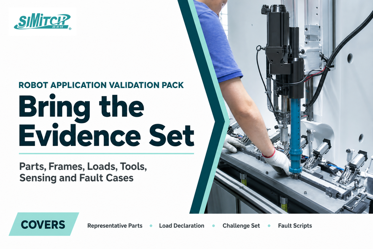
A Robot Application Validation Pack gives reviewers the parts, frames, load declaration, paths, tool interfaces, sensing challenges, process evidence, and fault cases needed to judge one robot task. It stops before whole-line quotation, station balancing, plant interfaces, and project-commercial allocation.
Use drawings and representative parts, but document robot behavior as well as geometry. Circuit board connector insertion, screwdriving, press fitting, and sheet-metal riveting can all use a robotic arm while demanding different compliance, tool-center-point control, force or torque evidence, inspection, and failed-part handling. The NIST robot-performance report supports defining the measured characteristic and test condition instead of treating a catalog value as application evidence.
| Pack item | What to supply | Robot-task question answered | Review evidence |
|---|---|---|---|
| Representative parts | Normal and boundary samples, variants, defects | Can presentation and gripping tolerate real variation? | Challenge-set result and exclusions |
| Frames and geometry | Part, fixture, tool and robot reference definitions | Is the tool center point reachable in required poses? | Frame check and reviewed path |
| Load declaration | Mass, center of gravity, inertia, cables and adapters | Does the load fit the working posture and motion? | Sizing record tied to configuration |
| End-effector interface | Grip or tool function, utilities, compliance, wear limits | Can the tool create and verify the intended result? | Tool-state and maintenance checks |
| Fixture datum | Location scheme, clamping and reaction path | Is the part constrained for motion and process loads? | Seating, clamp and datum results |
| Vision challenge set | Good, bad and borderline features under expected conditions | Can sensing distinguish actionable states? | Images, confidence rule and calibration record |
| Process result | Acceptance method, measured variables and disposition | What proves success beyond robot-complete? | Part-linked result record |
| Fault scripts | No part, lost grip, no-read, tool fault, interrupted cycle | Can the cell recover a known state without losing evidence? | Observed recovery and restart result |
This pack is a technical feasibility record, not a whole-line request-for-quotation checklist. After the robot task is defensible, line-level scope, commercial inclusions, site work, and supplier boundaries can be handled in the broader automated-line planning process.
Bring evidence for one robot task
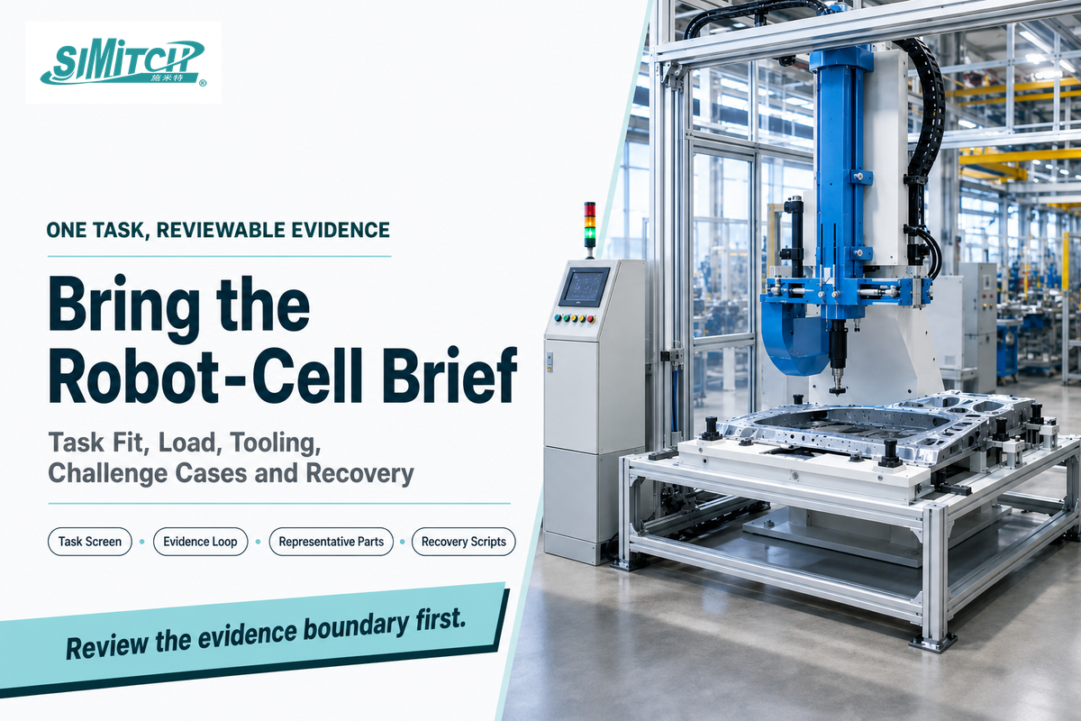
Use the task-readiness screen, Robot Task Evidence Loop, representative parts, load declaration, challenge cases, and recovery scripts to make the cell concept reviewable. Keep the integration boundary aligned with the applicable requirements; the public ISO 10218-2:2025 scope covers industrial robot applications and robot cells.
Frequently Asked Questions
What does robotic assembly line mean in this guide?
Here, robotic assembly line means the robot-centered part of production: defined robot tasks plus the tooling, presentation, sensing, process control, evidence, and recovery that make those tasks reviewable.
The scope may include one robot cell or several related robot tasks, but it does not absorb whole-line takt, buffers, shared transfer, station balancing, or plant-level acceptance. Those decisions belong to the broader automated-line architecture. Use the line-level article when the decision is how proven cells share takt, buffers, transfer, station interfaces, and plant controls.
What are assembly line robots?
Assembly line robots are programmable industrial robots or collaborative robots assigned to operations such as picking, insertion, fastening, joining, dispensing, or inspection within a controlled cell.
Robots are used to pick, orient, insert, fasten, join, dispense, or inspect. They become useful only when the incoming part state, tool access, required result, and exception path are defined. The same assembly robot can be unsuitable if the feeder, fixture, end effector, or validation method can’t support expected variation or efficient assembly.
What components make up a complete assembly cell?
A complete robotic assembly system combines the controller and motion platform with part presentation, fixtures, end effectors, process tools, sensing, transfer interfaces, cell controls, traceability, safeguarding interfaces, and recovery methods.
It normally includes the robot and controller, end effector, part-feeding equipment, fixture and datum strategy, process tool, vision system or other sensors, transfer interface, cell controls, traceability, safeguarding interfaces, and a recovery method. The exact combination depends on the task. That robot-complete signal alone doesn’t prove the part met its required condition.
Can robots be used for small-part assembly?
Robots can assemble small parts when feeding, orientation, location, manipulation, joining, and inspection remain reliable despite tight clearances, flexible components, reflective surfaces, static, contamination, and possible connector damage.
Small size doesn’t automatically make a task easy. Flexible components, reflective surfaces, tiny clearances, orientation ambiguity, static, contamination, and connector damage can dominate the design. Evaluate the complete presentation, fixture, tool, sensing, and recovery chain with representative parts.
How do assembly robots achieve precision and consistency?
Assembly robots achieve precision and consistency through calibrated motion, stable tooling and datums, controlled loads, sensing, process control, maintenance, and measurement across representative conditions rather than through robot repeatability alone.
Application accuracy and precision depend on calibration, load, tool center point, fixture datum, part tolerance, compliance, sensing, process control, temperature, maintenance, and measurement method. Validate the actual cell across representative conditions instead of transferring a catalog repeatability value directly to the assembled feature.
What information is needed before a robot-cell concept can be priced?
A robot-cell concept needs a defined task, representative parts, frames, load and inertia data, paths, tooling, sensing challenges, process evidence, safeguarding assumptions, and recovery cases before pricing is meaningful.
Those inputs expose whether the robot, end effector, presentation method, fixture, sensing and process tool can support the task. Record the tool-center-point frame, carried mass, center of gravity, inertia, working poses, cable routing, part extremes, fixture datum, vision challenge set, process-result method, interrupted-cycle states, and recovery evidence. Test that set before treating a demonstration as a priceable cell concept, and name every assumption that has not yet been validated. These inputs do not create a comparable whole-line quotation; site work, line controls, shared transfer, supplier boundaries, training, spares and production support require a separate commercial scope.
Research Transparency
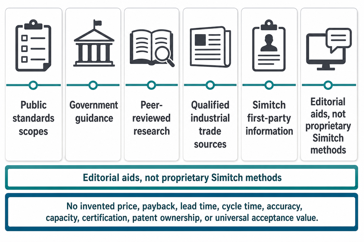
This guide uses public sources including the ISO 10218-2:2025 scope, OSHA robot-systems guidance, peer-reviewed research, qualified industrial trade sources, and first-party company information supplied for Simitch. The Robot Task Evidence Loop and Robot Application Validation Pack are editorial aids, not patented or proprietary Simitch methods. No private customer result, invented price, payback, lead time, cycle time, accuracy, capacity, certification, patent ownership, or universal acceptance value is claimed.
References & Sources
- ISO 10218-2:2025, industrial robot applications and robot cells
- OSHA Technical Manual, Industrial Robot Systems and Industrial Robot Applications
- NISTIR 7901, Performance Assessment of Three-dimensional Robot Systems
- Applied Sciences, human-robot task-allocation study
- Feedall, Robotic Part Feeding with Flexible Automation Cells
- Assembly Magazine, Robotic Parts Feeding — supplementary reading, not used as claim evidence in this guide.
- Association for Advancing Automation, updated ISO 10218 overview
- NIST, Assembly Performance Metrics and Test Methods
- CDC and NIOSH, Hazardous Energy Control