Get in touch with Suzhou Simitch Machinery Co., Ltd Company

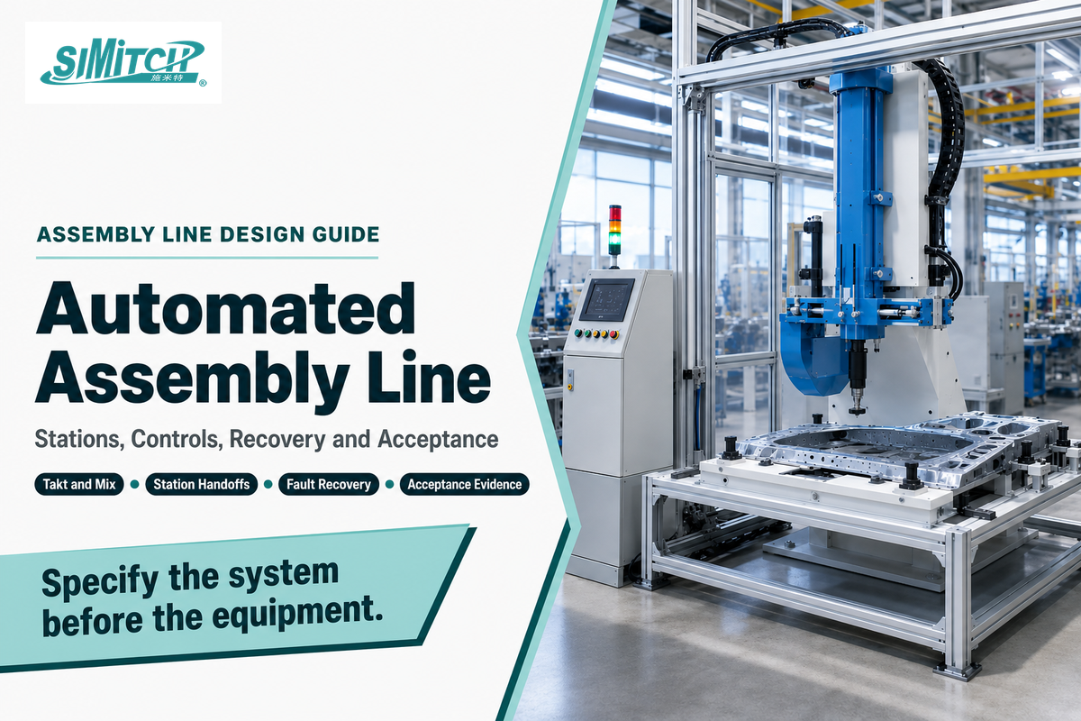
An automated assembly line is a linked production system, not a row of robots. Usable designs connect process steps, material flow, controls, verification, recovery, and the people responsible for every boundary. If one layer is left implicit, the equipment may run in isolation while the combined line still fails to meet rate, quality, or acceptance needs.
For product-family context, see SIMITCH servo press systems.
This guide turns demand into station scopes, buffer decisions, control handshakes, witnessed tests, and a comparable request for quotation. It is a buyer framework, not a complete safety, cybersecurity, or metrology standard; the project team must identify all application-specific legal, process, environmental, and customer requirements.
Updated August 2026 · By XCX
Quick Design Sequence
| Demand input | Net available time, required output, product mix, planned stops, and ramp assumptions |
| Architecture output | Station tasks, transfer path, constraint, buffers, controls, and inspection points |
| Interface record | State, part identity, owner, response, recovery, and evidence at every handoff |
| Acceptance evidence | Defined condition, threshold, sample, measurement method, witness, and retained record |
| Commercial boundary | Explicit inclusions, exclusions, utilities, documentation, training, spares, and support |
Design the line in this order: demand and mix → process sequence → stations and buffers → technology dependencies → controls and recovery → acceptance evidence → supplier scope. Equipment selection comes after the first three steps, not before them.
Five questions to keep visible
- What exact part state enters and leaves each station?
- Which station constrains output under the actual product mix?
- What happens when a part, signal, sensor, or inspection result is late or wrong?
- Who owns automatic recovery and who owns human intervention?
- What evidence proves the combined line met the agreed conditions?
What an Automated Assembly Line Actually Includes
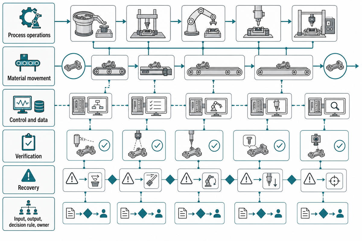
An automated assembly line links five layers: process operations, material movement, control and data, verification, and recovery. Every layer needs an input, an output, a decision rule, and an owner. Robots, feeders, conveyors, presses, joining tools, gauges, and software are components inside that system boundary.
The sequence usually begins with part presentation and identity. Each station then locates the part, performs an assembly operation, checks the result, and releases a known part state to the next step. Failed checks must route the part and preserve enough information to diagnose, contain, rework, or reject it.
That distinction matters commercially. One supplier may quote a robot and fixture, another a feeder, and another a joining process; none automatically owns the combined behavior. ISO 10218-2:2025 supports an integration view for industrial robot applications and cells, but its scope is narrower than every hazard and process on a complete production line.
Architecture terms that change the scope
In this guide, an automated production line links multiple assembly stations, while a workstation may be one manual, semi-automated, or robotic assembly step. Fixed automation, sometimes called hard automation, favors stable high-volume production; programmable or flexible automation handles more product complexity and recipe change. Soft automation is a less precise commercial label, so a request should name the actual change method and limits.
Typical automation solutions combine pick and place, an actuator or robot, an automated assembly fixture, transfer, machine vision, process tooling, and quality control. These automation systems, like other automated systems, can reduce selected manual labor and improve throughput only when the production process, defect response, maintenance, labor costs, operational costs, and required productivity are defined. “Fully automated” is therefore a scope claim, not a synonym for minimal downtime.
Automation applications range from one high-precision workstation to robotic automation across several production environments. For automation in manufacturing, describe the assembly tasks and required result before naming the automation technology. That keeps manufacturing automation tied to the product instead of to a generic equipment label.
Process
What changes on the product?
What changes on the product?
Flow
How does a known part arrive and leave?
How does a known part arrive and leave?
Control
Which state and recipe authorize action?
Which state and recipe authorize action?
Verification
What detects a conforming result?
What detects a conforming result?
Recovery
How is a disturbance contained and cleared?
How is a disturbance contained and cleared?
How does assembly line automation work?
Parts enter with an identity and expected recipe. Each station confirms that it is ready, receives or creates the required part state, performs its task, verifies the result, records data, and authorizes transfer. The line controller coordinates conditions such as route, model, stop, restart, and reject handling. When a fault occurs, recovery must restore both the physical part state and the digital state; resetting an alarm without reconciling those two states can release the wrong part or repeat an operation.
Treat assembly line design, assembly line layout, and line balancing as connected decisions. Moving a station changes travel, access, buffer behavior, the assembly line control system, and the conditions that must be retested.
Start With Takt, Product Mix, and Process Sequence
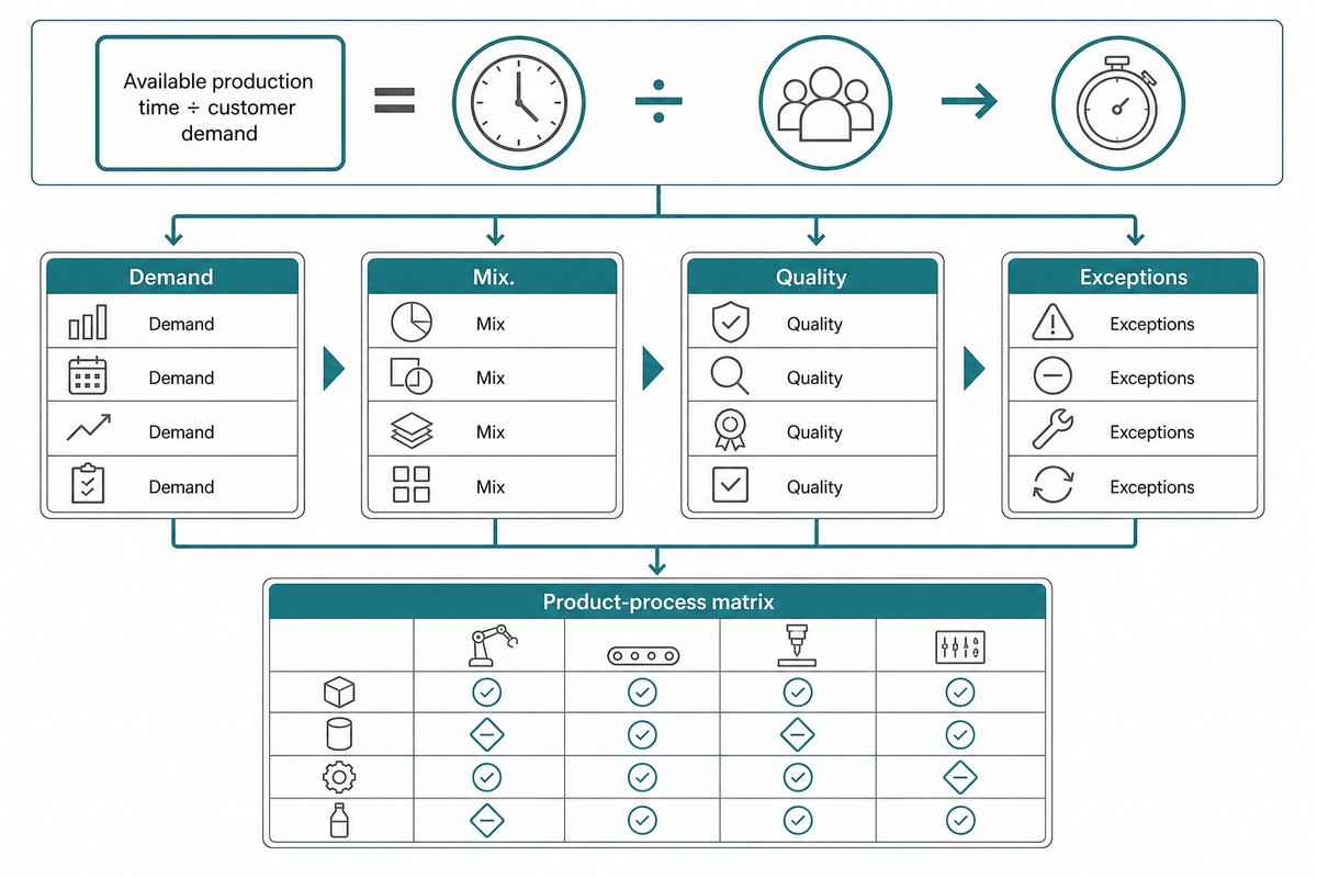
Takt time is available production time divided by customer demand. It sets a demand-rate reference for the line, not a guarantee that every station can achieve that rate. Product mix, task-time variation, transfer, inspection, planned stops, changeover, and recovery still need to be modeled and tested.
Hypothetical takt example
420 net minutes ÷ 210 required units = 2 minutes per unit
The 420 minutes and 210 units are teaching inputs, not Simitch or customer production data. A station with a two-minute average can still miss the required output if its long-cycle tail, faults, variant change, or blocked time is not represented.
Build a product-process matrix before dividing work into stations. For every variant, list the required tasks, precedence, optional routes, joining recipe, inspection, rework rule, and the part feature needed by the next operation. Then separate value-adding process time from transfer, sensing, clamping, data exchange, and release time.
A 2025 robotic-line study cited in the adversarial review found that greater task-time uncertainty reduces predictability of cycle time, output efficiency, and workload balance. The practical response is not to discard takt; it is to test distributions and variant sequences rather than treating one average as deterministic capacity.
| Input | Minimum useful detail | Risk if omitted |
|---|---|---|
| Demand | Units by shift, net time, ramp profile | Nominal rate hides calendar losses |
| Mix | Variant share and sequence constraints | Average work content hides peaks |
| Quality | Feature, method, threshold, response | Inspection is priced but not actionable |
| Exceptions | Missing part, bad read, failed joint, re-entry | Recovery is designed during commissioning |
Turn the Process Into Stations and Buffers
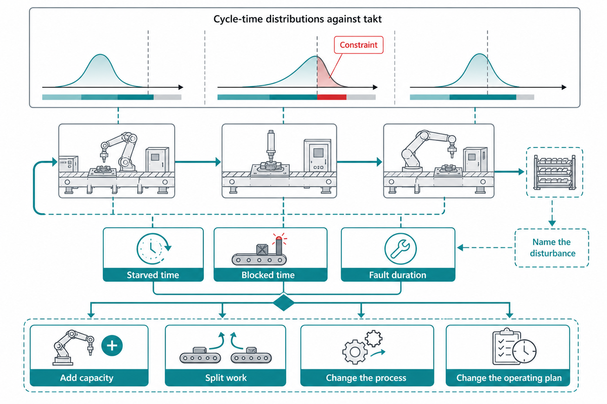
Create stations by grouping precedence-compatible tasks, then compare their cycle-time distributions against takt. The constraint is the station or shared resource that limits the combined line under the intended mix. Buffers should be assigned to a named source of variability, never used to conceal a permanently overloaded station.
Track more than average cycle time. Record starved time, blocked time, fault duration, manual intervention, planned replenishment, and the tail of the cycle distribution by model. If one operation structurally requires longer than the demand interval, add capacity, split work, change the process, or change the operating plan before sizing storage.
Peer-reviewed mixed-model research shows why there is no universal buffer rule. A 2024 study found sequencing more effective in scenarios with fewer models, while buffer allocation became more effective with considerably more models. Other work shows that buffer position, line topology, variability pattern, and equipment reliability can change the result.
Buffer decision note
Name the disturbance: short feeder interruption, inspection-time spread, downstream stop, variant sequence, replenishment, or merging flow. Then define capacity, full/empty response, ownership, and the condition that triggers a design change. “Extra buffer for safety” is not a testable requirement.
Choose Transfer, Feeding, Robotics, and Joining Together
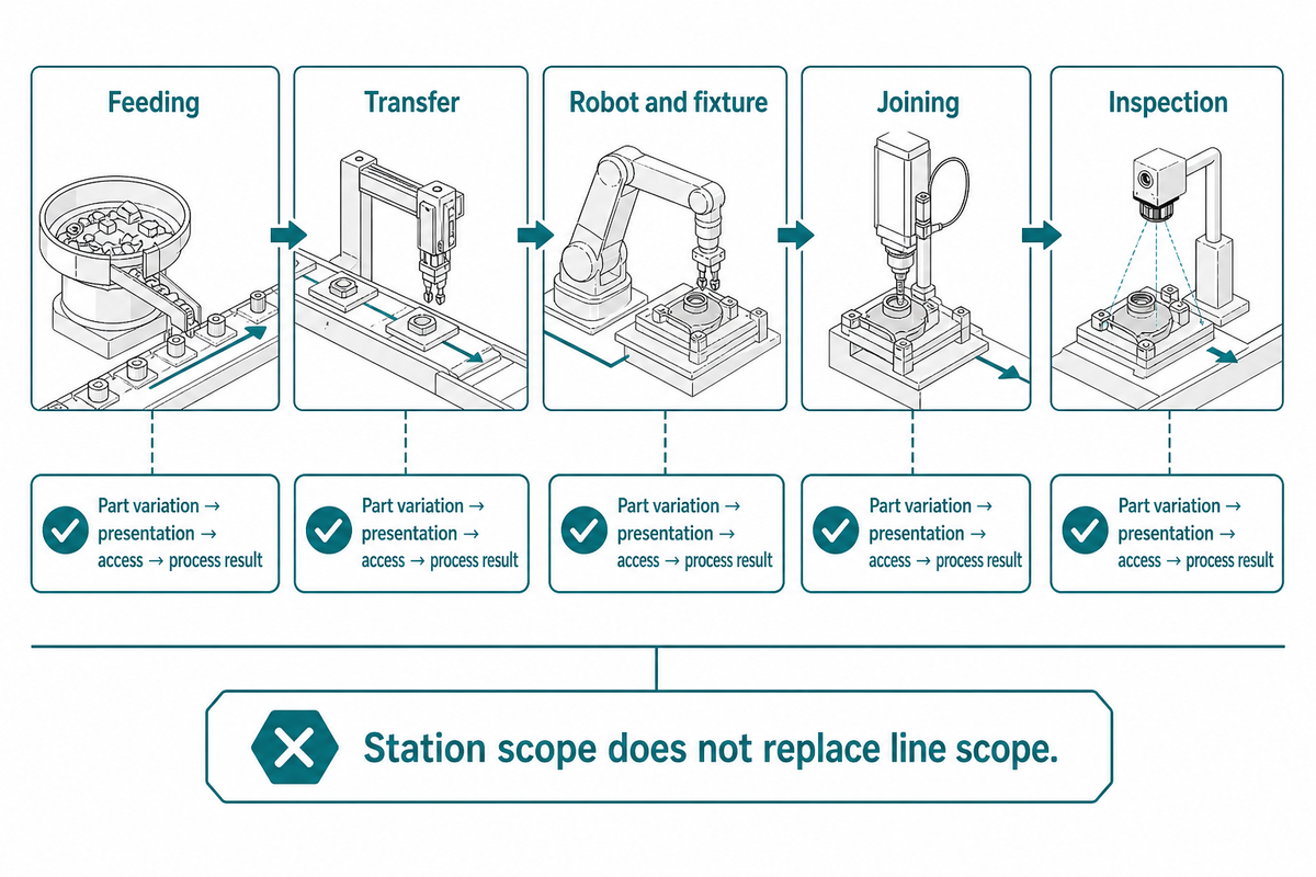
Choose technologies as a dependency chain: product variation affects feeding; presentation affects fixturing and robot access; access affects joining and inspection; the process result affects transfer and reject handling. A process can be technically suitable for the joint yet unsuitable for the line if the part cannot be presented, stabilized, verified, or recovered at the required rate.
| Decision | Ask first | Downstream dependency | Evidence |
|---|---|---|---|
| Feeding | Can every variant be separated and oriented? | Stable pickup and known identity | Range, refill, jam, wrong-part trial |
| Transfer | What part state must survive movement? | Datum, contamination, curing, cooling | Blocked/starved and accumulation test |
| Robot and fixture | Are reach, payload, cable, tolerance, and access compatible? | Process path and maintenance access | Reach study plus representative trial |
| Joining | Does the actual stack fit the process window? | Force, access, consumable, quality signal | Joint, process, inspection, repair evidence |
| Inspection | Can the critical result be measured in cycle? | Reject route and traceability | Detection study and challenge parts |
When the architecture narrows to a controlled riveting station, review the required process, force, fixture, handling, and verification interfaces before comparing servo riveting assembly systems. That station-level route does not replace the line-level demand, buffer, control, safety, and acceptance work described here. Use the parent riveting equipment routes and the metal joining methods selection guide when the process family is not yet fixed.
Whether a station must weld, solder, press, rivet, clinch sheet metal, fasten, or dispense adhesive, the line still needs a stable incoming part state and an observable result. Industrial automation changes the handling and control method; it does not remove the process-specific qualification boundary.
According to company information supplied for this guide, Simitch was established in September 2006 in Taicang, Jiangsu, and focuses on intelligent joining equipment. Its stated scope includes hydro-pneumatic boosters, precision servo pressing, and lightweight sheet-metal joining technologies such as Clinching, Riveting, SPAC, and SPR for sectors including automotive components, energy storage batteries, solar photovoltaic, home appliances, and HVAC terminals. This is first-party scope information, not evidence of a project result, certification, capacity, or universal process fit.
Need to define a joining station inside a larger line?
Bring the part stack, target rate, upstream presentation, downstream inspection, changeover, and recovery conditions into the discussion. That input lets the project team separate the joining-station boundary from line-level transfer, controls, guarding interfaces, traceability, and acceptance responsibilities before comparing a system scope.
Define the Control System and Data Handshakes
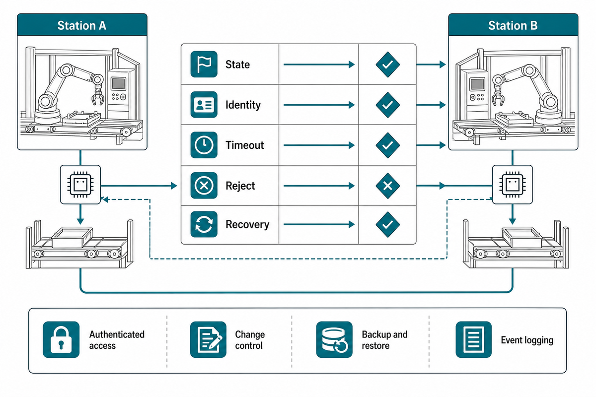
At each boundary, define current state, permitted transition, part identity, recipe, timeout, fault, bypass, reject, and recovery owner. Use a common state vocabulary where it fits, but do not impose one universal tag list. The actual information model, application, risk assessment, and traceability requirements determine the interface.
ANSI/ISA-TR88.00.02-2015 provides machine and unit states, modes, and transitions. OPC UA Part 16 also models current state, last transition, transition causes, events, and extensible sub-state machines. These sources support explicit semantics; they do not decide the business rule for every station pair.
| Field | Question | Example response |
|---|---|---|
| State | Which transition authorizes transfer? | Completed → ready to release |
| Identity | How is the physical part bound to its record? | Carrier ID plus variant and route |
| Timeout | When does waiting become a controlled fault? | Defined time plus hold response |
| Reject | Who contains a failed result? | No release; route and record reason |
| Recovery | Who reconciles physical and digital state? | Named owner and verified restart point |
Cybersecurity belongs inside this interface scope. Define authenticated access, remote-support authorization, recipe and software change control, backup and restore, event logging, and the owner who can return the system to a trusted state. NIST manufacturing-control guidance warns that loss of system integrity can affect both operations and worker safety. The publication supplies a hazard model, not proof of current compliance or a replacement for a project-specific cybersecurity assessment.
Plan Changeovers, Fault Recovery, and Scalability
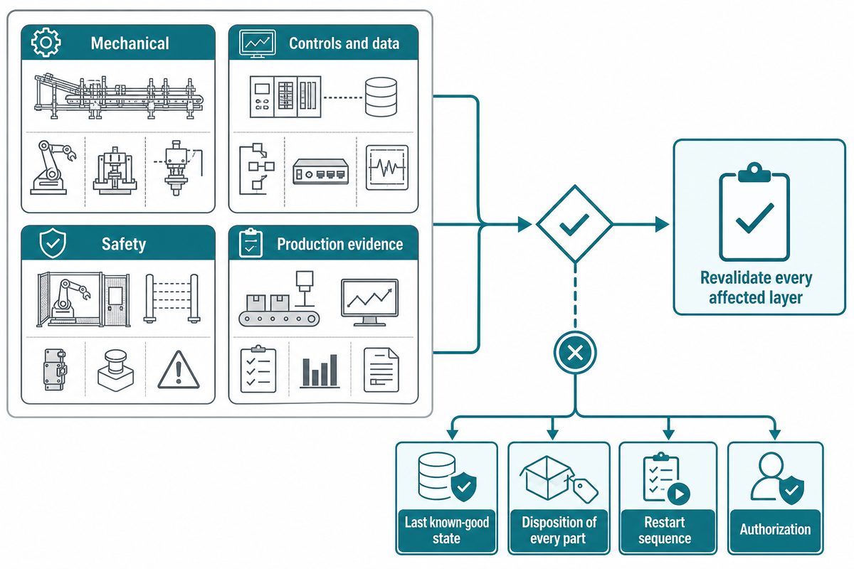
Separate a change into mechanics, controls and data, safety, and production evidence. A modular frame does not make recipes, utilities, interlocks, traceability, validation, or recovery modular. After a product, station, or logistics change, revalidate every affected layer before calling the line scalable.
For changeover, identify what changes automatically, what requires tooling, what must be verified, and what prevents the wrong recipe or part combination. For recovery, name the last known-good state, disposition of every part in the affected zone, restart sequence, authorization, and evidence that the disturbance was cleared.
Non-routine work needs its own branch. U.S. OSHA guidance notes that robot incidents can occur during programming, setup, testing, adjustment, maintenance, and fault recovery when human workers may enter the working envelope. Cobots that work alongside human workers still require an application-specific risk assessment and validated protective measures. This jurisdiction-specific guidance identifies exposure modes; it is not presented as the current legal rule for every market. An automatic restart sequence is therefore not a complete recovery plan.
Mechanical
Tooling, datum, reach, guarding interface, utilities, maintenance clearance.
Controls and data
Recipe, identifiers, states, versions, logs, backups, remote access.
Safety
Applicable functions, modes, intervention, validation, documentation.
Production evidence
Rate, quality, changeover, recovery, traceability, trained support.
Can existing manual assembly processes be automated?
Yes, but begin by stabilizing the manual process and measuring its variation. Separate repeatable work from judgment, exception handling, replenishment, and rework. Automate tasks with defined inputs and observable outputs, then design routes for missing, damaged, misoriented, or out-of-tolerance parts. Integrate the automated tasks in sequence only after their interfaces and recovery states are explicit. If variation is transferred into a feeder, robot, or inspection station without a response plan, the line may automate the stop rather than the work.
Use the 8-Field Station Handoff Contract to Assign Ownership
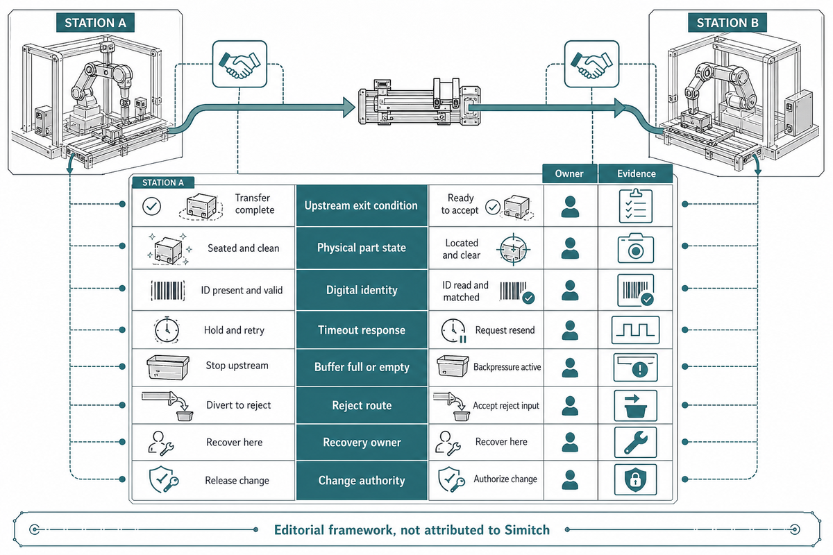
The Station Handoff Contract is an editorial decision aid that records what leaves one station, what the next station accepts, who owns the signal and response, how buffering behaves, who recovers the boundary, and what evidence closes it. The term is used here for an editorial framework; it is not attributed to Simitch or presented as a performance guarantee.
A line boundary is not closed until state, owner, response, recovery, and acceptance evidence are defined. This rule separates a supplier’s local completion claim from proof that the combined interface works.
A boundary is not closed when both suppliers simply mark their own station complete. It is closed when the combined interface has a measurable state, an owner, a defined abnormal response, a recovery owner, and retained acceptance evidence. NIST component-behavior research and OPC state semantics support the need for explicit behavior, while the particular record below is a buyer-created synthesis.
| Field | Example entry | Owner | Acceptance evidence type |
|---|---|---|---|
| Upstream exit condition | Process complete and verification passed | Station A | Witnessed pass and forced-fail trial |
| Physical part state | Located on carrier, feature protected | Transfer supplier | Representative variant transfer |
| Digital identity | Carrier, part, variant, recipe, result linked | Controls lead | Trace record and mismatch challenge |
| Timeout response | Hold release and generate defined fault | Line integrator | Timed fault injection |
| Buffer full/empty | Controlled blocked/starved state | Line integrator | Full and empty boundary tests |
| Reject route | Contain, record, and prevent normal release | Quality owner | Challenge part and record review |
| Recovery owner | Reconcile all physical and digital states | Named role | Interrupted-cycle recovery trial |
| Change authority | Approved version and rollback path | Project owner | Version, backup, restore, and approval record |
Commission and Accept the Line With Measurable Evidence
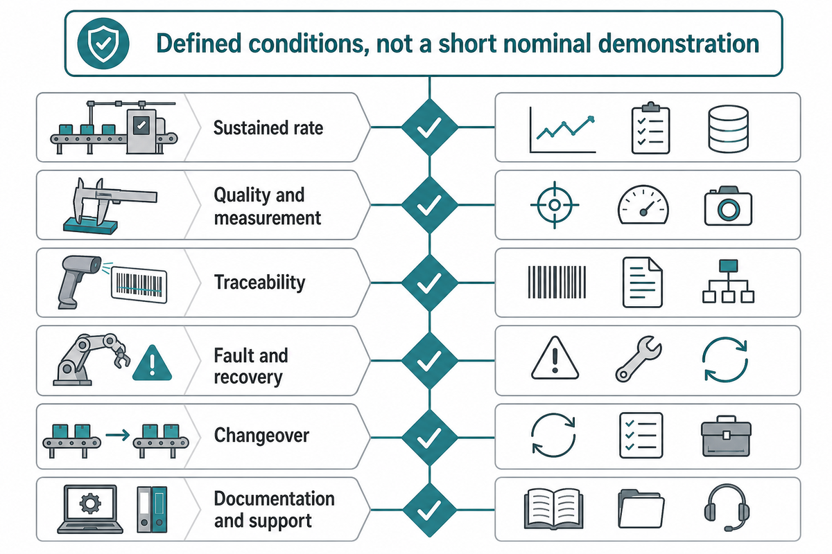
Accept a line against defined conditions, not a short nominal demonstration. Specify the product mix, input condition, test duration, threshold, sample, allowed interventions, measurement method, evidence owner, and response to failure. Test rate, quality, traceability, changeover, faults, recovery, safety functions, documentation, and support separately.
Pre-commissioning or a factory acceptance test can expose integration issues before shipment, while site acceptance verifies the installed system with site utilities, interfaces, materials, and personnel. A Siemens-hosted case involving Smart Automation and BRUSS documents a sequence from concept work in June 2023 through pre-commissioning, on-site testing, and formal acceptance in December 2024. It illustrates sequence, not a guaranteed schedule or Simitch result.
Measurement evidence needs context. Record the instrument, calibration or status, sampling method, tolerance, uncertainty or capability rationale, and who interprets the result. NIST metrology guidance supports the flow of tolerance and measurement-uncertainty information through design, production, and inspection.
| Test family | Condition to define | Evidence to retain |
|---|---|---|
| Sustained rate | Mix, duration, planned stops, input supply, allowed intervention | Time-stamped output, blocked/starved/fault states |
| Quality and measurement | Feature, tolerance, instrument, sample, uncertainty/capability | Results, challenge pieces, calibration/status |
| Traceability | Identity, recipe, result, reject, re-entry | Matched physical and digital records |
| Fault and recovery | Injected faults, parts in zone, restart authority | Alarm, containment, reconciled state, restart |
| Changeover | Variant path, tooling, recipe, verification | Elapsed steps, first-good evidence, wrong-recipe challenge |
| Documentation and support | Drawings, software, versions, backups, training, spares | Controlled handover and restore demonstration |
Scope limit: ISO 10218-2:2025 concerns industrial robot applications and cells and does not cover every process or environmental hazard in a whole line. Identify applicable requirements for material processing, hygiene, noise, explosive atmospheres, mobile equipment, utilities, cybersecurity, and other project conditions separately.
What Is Changing in Assembly Automation—and What It Means for Buyers
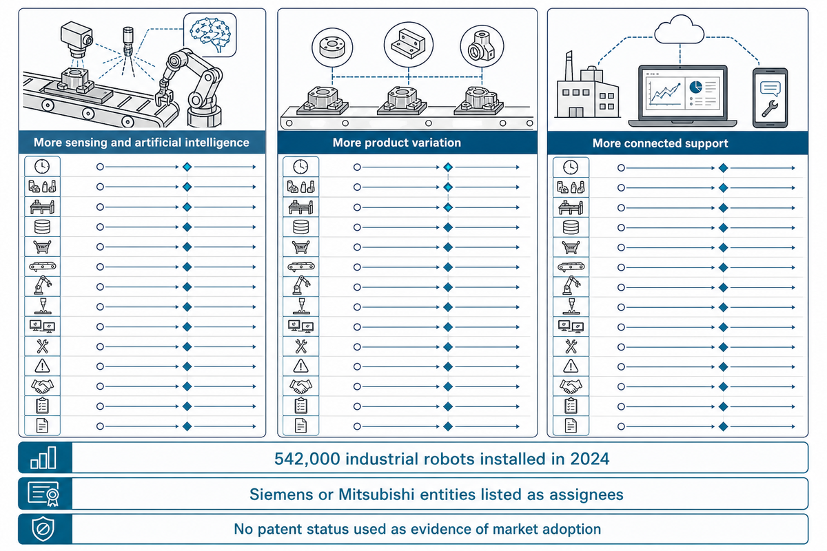
Automation adoption remains substantial, but the useful buying signal is not “add more robots.” It is to require clearer interfaces, flexible product handling, maintainable data and controls, validated sensing, workforce readiness, and recoverable operation. Regional demand and individual factory economics can still move differently.
The International Federation of Robotics reported 542,000 industrial robots installed in 2024, with annual installations above 500,000 for a fourth year. The same source shows uneven regional movement, so historically high global demand should not be presented as uninterrupted growth in every market.
More sensing and artificial intelligence
Require training-data boundary, validation method, fallback state, maintenance owner, and change control.
More product variation
Require variant rules, mistake-proof identity, quantified changeover, and revalidated process windows.
More connected support
Require authenticated remote access, logs, version control, backups, restore testing, and ownership.
Patent records provide a separate research signal, not supplier proof. Current records describe assembly-line knowledge graphs, modular handover areas, and force-based robotic error recovery, with Siemens or Mitsubishi entities listed as assignees. None of those records is attributed to Simitch, and no patent status is used as evidence of market adoption.
Build an RFQ That Exposes Integration Risk
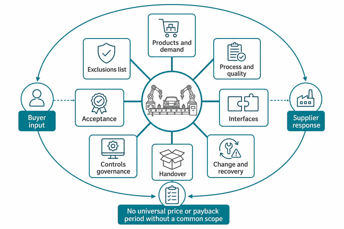
A useful request for quotation gives every bidder the same products, demand assumptions, process and quality requirements, interfaces, utilities, changeover and recovery cases, acceptance conditions, documentation, and ownership boundaries. It also requires an exclusions list, so a lower price cannot hide missing feeders, gauges, guarding interfaces, traceability, training, spares, or site support.
| Scope block | Buyer input | Supplier response | Required exclusion disclosure |
|---|---|---|---|
| Products and demand | Variants, drawings, mix, net time, ramp | Supported envelope and assumptions | Unquoted variants and future volume |
| Process and quality | Critical features, checks, reject/rework | Process route and verification concept | Trials, gauges, destructive audits |
| Interfaces | Upstream/downstream states and owners | Signal, data, transfer, buffer responsibilities | Third-party integration and licensing |
| Change and recovery | Variants, change cases, injected faults | Sequence, access, restore and restart | Manual work and untested disturbances |
| Controls governance | Access, change authorization, retention | Accounts, versions, backups, logs, remote support | Subscriptions, owner licenses, hosted services |
| Acceptance | Conditions, thresholds, sample, witness | Factory/site test plan and evidence | Materials, travel, retest, production support |
| Handover | Document and training requirements | Drawings, software, backups, manuals, spares | Source access, proprietary tools, future support |
Do not ask for a universal price or payback period without a common scope. A cost-effective proposal is one that meets the defined performance and lifecycle boundary at an acceptable total cost, not necessarily the quote with the lowest initial number. Compare production costs together with included hardware, engineering, trials, installation, site support, spares, licenses, utilities, training, maintenance, and changeover burden on the same basis.
Turn the line concept into a reviewable scope
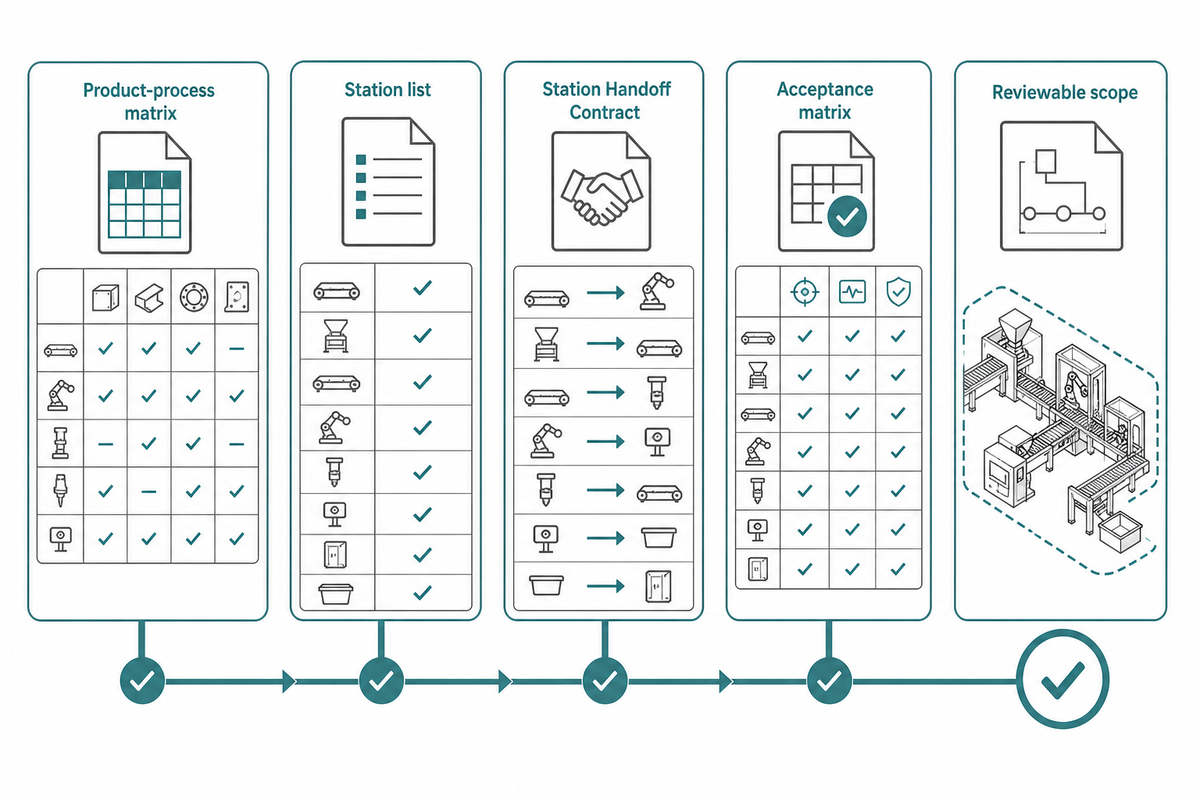
Prepare the product-process matrix, station list, Station Handoff Contract, and acceptance matrix before requesting comparable proposals.
Frequently Asked Questions
What is an automated assembly system?
Answer
An automated assembly system combines equipment, material handling, controls, sensing, verification, data, and recovery to assemble products with limited routine manual action. It may be one cell or a linked production line. The useful definition includes how parts enter, how identity and recipe are controlled, what each operation changes, how results are checked, and what happens when a part or station does not meet the expected condition.
What are the four main types of assembly lines?
Answer
A practical four-part classification is manual, semi-automated, fixed automated, and flexible or mixed-model assembly. The labels describe how work and variation are handled; they do not determine the best architecture by themselves. Many real lines are hybrids, with manual loading, automated processing, robotic transfer, in-line inspection, and a controlled manual rework route. Classify each operation and exception rather than forcing the whole factory into one label.
Can existing manual assembly processes be automated?
Answer
Yes, when the work has defined inputs, repeatable tasks, measurable outputs, and manageable exceptions. Stabilize the manual method, measure variation, automate suitable tasks, and design routes for missing or nonconforming parts. Then integrate the tasks with explicit state, identity, recovery, and acceptance rules. Automation should remove or control variation, not hide it inside a feeder, robot, vision system, or operator intervention.
How does automation improve product quality?
Answer
Automation can repeat motion, settings, inspection, and records. Quality improves only when detection is capable, failed results are contained, drift has a response, and measurement evidence is interpretable.
How much does an automated assembly system cost?
Answer
There is no responsible universal price band. Cost changes with product variants, part presentation, feeding difficulty, station count, transfer, process equipment, robots, fixtures, inspection, traceability, guarding interfaces, controls, cybersecurity, site utilities, trials, validation, documentation, training, spares, installation, travel, and production support. Ask suppliers to quote the same demand and product envelope, then require inclusions, exclusions, assumptions, optional items, licenses, and third-party responsibilities to be visible. Compare initial price with changeover labor, consumables, maintenance, floor space, utilities, software ownership, remote support, downtime exposure, spare-parts policy, expected modification work, and the internal resources needed to sustain the line. A number without that common boundary is not a comparable system cost.
How long does it take to see a return on investment?
Answer
No universal ROI or payback period is defensible. Calculate return on investment from verified baseline labor, scrap, output, downtime, maintenance, working capital, implementation cost, ramp losses, and the probability that product volume and mix remain within the design envelope. Test multiple demand and reliability scenarios before approving the result.
Research Transparency
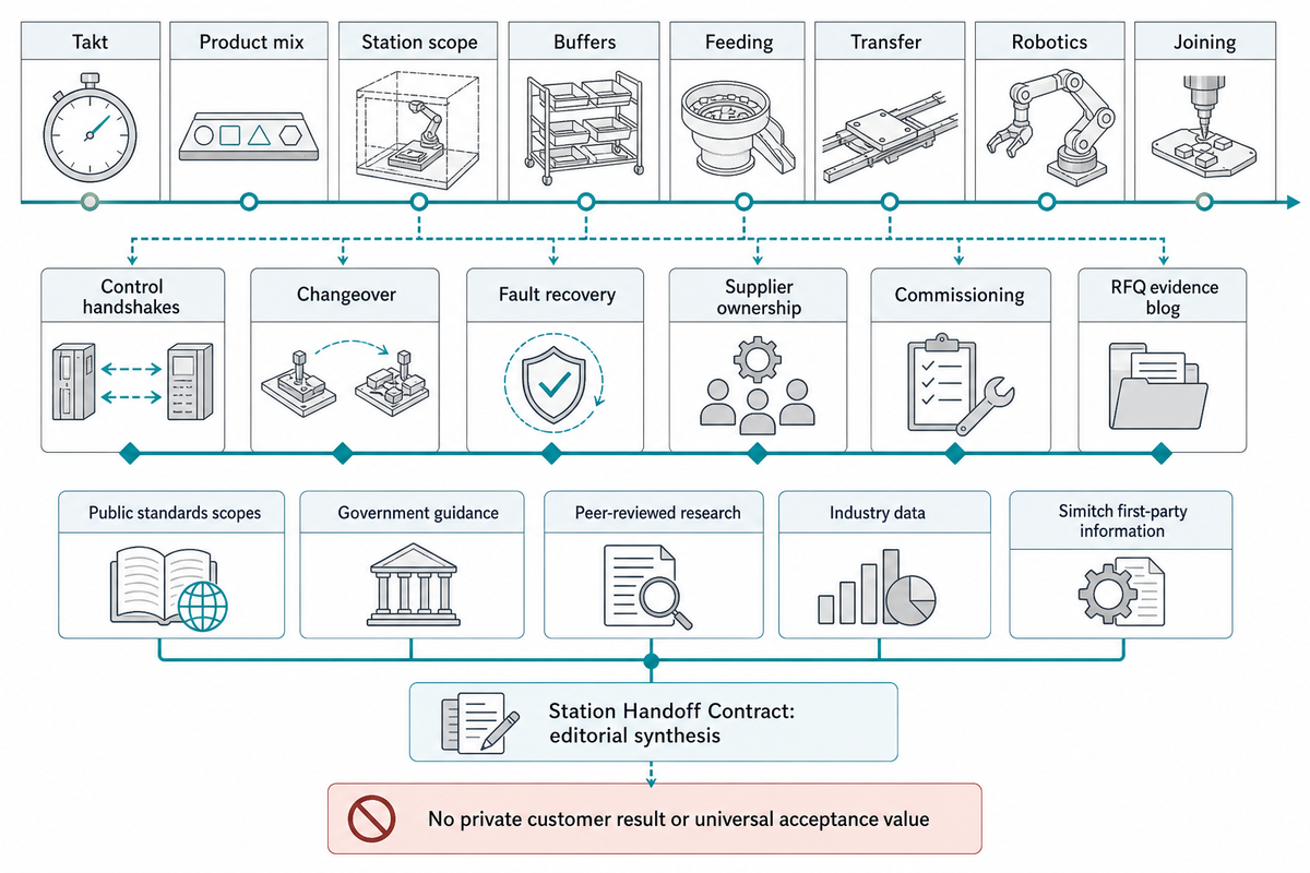
This guide uses current public standards scopes, government guidance, peer-reviewed research, industry data, disclosed practitioner experience, and first-party company information supplied for Simitch. The Station Handoff Contract is editorial synthesis. No private customer result, invented price, payback, lead time, cycle time, accuracy, capacity, certification, patent ownership, or universal acceptance value is claimed.
References & Sources
- ISO 10218-2:2025, industrial robot applications and robot cells
- ISO 13849-1:2023, safety-related parts of control systems
- ANSI/ISA-TR88.00.02-2015, machine and unit states
- Lean Enterprise Institute, takt time definition
- 2024 peer-reviewed study of mixed-model line balance, buffers, and sequencing
- NIST, behavioral requirements for component-based machine controllers
- OPC UA Part 16, State Machines
- Frontiers, modular line-less assembly demonstrator
- NIST, protecting industrial control system integrity
- OSHA, robotics hazards and controls
- NIST, tolerances and uncertainty in robotic systems
- International Federation of Robotics, 2024 installation data released in 2025
- Siemens-hosted BRUSS and Smart Automation case study
![Hot-Melt Connection Molds & Equipment Guide [2026]](https://simitch.com/wp-content/uploads/2026/09/hot-melt-connection-molds-equipment-guide-featured-768x512.png)