
Get in touch with Suzhou Simitch Machinery Co., Ltd Company

![Hot-Melt Connection Molds & Equipment Guide [2026]](https://simitch.com/wp-content/uploads/2026/09/hot-melt-connection-molds-equipment-guide-featured.png)
Tooling design review
Updated September 2026
Hot-Melt Connection Molds & Equipment refers to the tooling used to locate, support, heat, and form an existing plastic assembly during heat staking. Heat-staking projects can look straightforward until the tool must hold a real, variable assembly. It’s not enough to know whether a heated head can reach a plastic boss. The review must also confirm that the part can be located, supported, accessed, and safely connected to the machine carrying the tool. This SIMITCH tooling guide covers mold, nest, staking-head, and fixed-interface decisions before a representative-part trial. It doesn’t choose a production cell, set a process window, or claim process capability.
1. Define what “hot-melt connection molds & equipment” means before reviewing hardware
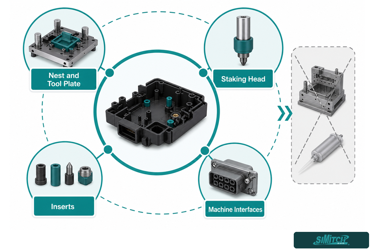
Hot-Melt Connection Molds & Equipment refers here to the tooling that locates, supports, and thermally forms an existing plastic assembly during heat staking or thermal staking. The word “mold” is used in the fixture sense: the nest, tool plate, staking head, inserts, and their interfaces. It doesn’t mean an injection mold that creates the original plastic component from resin.
The terminology check matters because the same search phrase can indicate different process families. Hot-melt adhesive dispensing creates an adhesive bond or seal, while low-pressure overmolding introduces molten material into a cavity. Ultrasonic joining and conventional welding use different energy paths. Heat staking uses localized energy to soften and reform a thermoplastic boss or stud against a mating part. These processes may join dissimilar materials, but they don’t share a common design review or hardware recipe. Industry coverage also describes several staking arrangements rather than one standard stack, which is a useful reminder to identify the energy path and joint function first.
Heat staking design guidelines tend to associate plastic heat staking with ultrasonic welding, since either process may join plastic to a metal part or to another molded plastic component. Here, plastic heat staking means controlled heat and pressure delivered through staking equipment to a pre-molded stud or boss. The tool contacts the mating component and forms a head; it doesn’t create an ultrasonic weld. This distinction helps us focus on the tool design rather than the route selection.
Tooling Stack Map
- Incoming part and joint definition
- Datum and nest contact strategy
- Local support beneath the forming load path
- Staking-head and energy-delivery architecture
- Thermal, electrical, pneumatic, and sensing interfaces
- Machine mounting, guarding, service, and revision-control boundaries
Joint appearance and geometry tend to be a primary concern of product designers. Manufacturing engineers often begin with repeatable location and maintenance access. Equipment buyers need the complete map because a machine envelope or controller channel count becomes meaningful only after the tool-side requirements are visible. Treating these as one conversation prevents a mold design from silently becoming an equipment specification, or the reverse.
2. Convert joint and incoming-part information into a controlled tooling input sheet
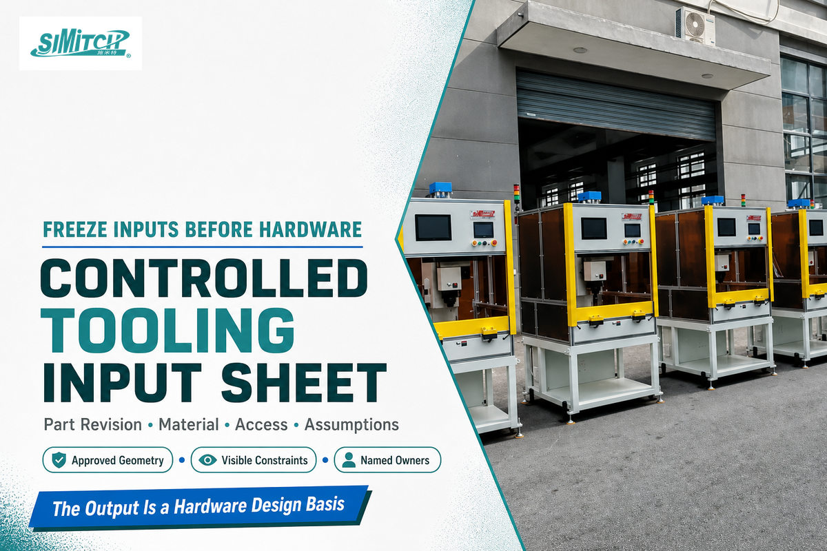
A tool is as stable as the information it’s given. Begin with the controlled drawing or approved 3D definition for each incoming part. Identify the revision that the review is using. Provide the boss and mating-part geometry, resin and filler information, manufacturing route, conditioning state, cosmetic surfaces, nearby heat-sensitive components, access restrictions, and the accepted variant list. Record the condition of the part as an input if there’s a risk of molded-in stress, warpage, surface treatment, or internal defects. In such cases, the production part may not be of nominal geometry.
The input sheet should also state the type of plastic and the feature being formed. Different access and support issues may arise from solid plastic posts, a plastic stud, or a hollow stake. Glass-filled material, nearby ribs, sink marks, or thin surrounding plastic may affect what the nest must support. Record those facts as part-specific constraints rather than turning them into generic dimensions or process settings.
This isn’t paperwork for its own sake. The peer-reviewed PA staking study found that geometry, alignment, force, temperature, defect condition, and manufacturing history interacted in the tested PA12 joint. Its results belong to that material and test context, not to every plastic assembly. The transferable design lesson is simpler: an incoming-part change can alter what the fixture must locate and support even when the machine has not changed.
Freeze inputs, expose assumptions.
Every unknown should appear as an owner-assigned assumption: which face may contact the nest, whether a cosmetic face may be clamped, or whether a variant uses a different datum. An unrecorded assumption becomes a late tool revision because no one can see that it was a decision.
Keep the input sheet separate from process development. It may identify a material, boss, or adjacent component that needs trial attention, but it shouldn’t prescribe temperature, dwell, force, or tolerance as though one number can cover every resin and tool architecture. In an automotive assembly or another mixed-fastener product, also flag threaded inserts as a separate route. Knurled metal inserts depend on insertion and thread retention, while heat staking reforms a plastic feature. The output is a design basis for hardware, not a staking process recipe.
3. Engineer the nest, support, and datum scheme around the actual load path
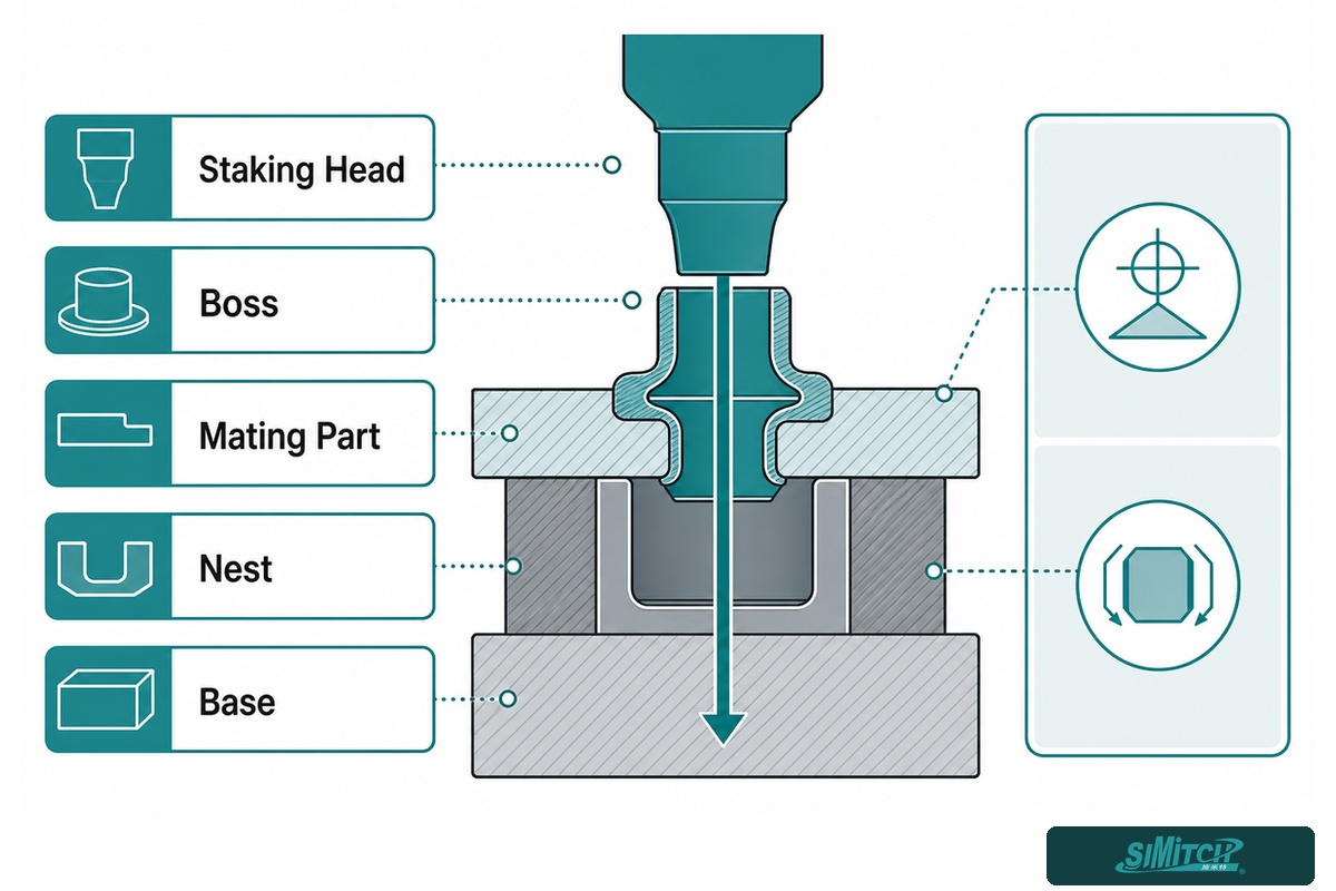
A nest should accomplish more than hold a part from falling. It needs to reliably establish the intended datum structure, restrain rotation where needed, and maintain support for the assembly close to the forming load path to prevent excessive bending or elastic movement into a false failure. The familiar 3-2-1 location concept is a useful mental model, but plastic assemblies are deformable and often cosmetic. The review must therefore ask which contacts establish position, which merely support, and which may deform or release during loading.
Start from the joint: trace the staking force through the head, boss, mating part, nest, and base. Then check the spaces between those contacts. Even a positioned part may move if the backing face is unsupported, a thin wall acts as a spring, or an anti-rotation feature engages late in the motion. Conversely, an over-constrained nest can distort a molded part or mar a cosmetic surface before any thermal action occurs.
| Variation source | Tooling symptom | Misleading machine symptom | Verification question |
|---|---|---|---|
| Datum face changes between variants | Part settles differently | Apparent head misalignment | Which controlled feature truly locates the part? |
| Insufficient backing support | Local deflection under load | Apparent force inconsistency | Is the load path supported at the joint? |
| Part rotates during placement | Boss no longer meets the intended tip position | Apparent poor parallelism | When does anti-rotation become active? |
| Contact on a cosmetic or compliant area | Marks or changing seat height | Apparent part-to-part drift | Which contacts are functionally permitted? |
Use this map as a review guide, not a universal failure ranking. Consider the loading position, whether access is provided to operators or automation, sensor clearance, whether fasteners can reach, and if change parts can be fitted without losing a reference surface. The machine may exhibit a symptom, but the root cause may be a poorly designed fixture.
4. Match staking-head architecture and energy source to part access
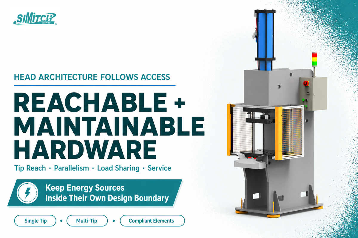
Head architecture translates the joint map into reachable, maintainable hardware. One tip can suit an isolated joint; a multi-tip platen can coordinate several locations; independent or compliant elements may help where part variation and head-to-part contact need deliberate management. Remote-access arrangements can solve reach constraints, but they usually demand closer attention to stiffness, alignment, service clearance, and tool identification.
Establish a rigid boundary around the energy source. This article focuses on contact-heated thermodes and their tooling interfaces. Impulse heating, hot air, infrared, and ultrasonic tooling use different heating paths, controls, hazard considerations, and acceptance questions. Don’t treat a tip shape or sensor arrangement from one method as interchangeable with another. The US10625474B2 patent disclosure, for example, presents low thermal mass, conductive construction, heater placement, and alternate sensor locations as implementation choices rather than an industry-wide rule.
| Interface type | Tooling must define | Machine-side review must confirm | Limitation or release condition |
|---|---|---|---|
| Base mounting | Mounting face, fastener pattern, base datum | Attachment method, rigidity, tool-change access | Do not release while the reference scheme is ambiguous. |
| Alignment | Head-to-nest references and restoration method | Adjustment range and locked reference | Do not approve an adjustment without a repeatable lock. |
| Motion envelope | Tip reach, loading path, removal and service clearance | Available travel, interference checks, safe access | A clear static model does not prove the operating cycle is clear. |
| Thermal | Heat path, insulation boundary, replaceable tip identity | Compatible heating control and heat-sensitive neighbors | Controller setpoint is not an interface-temperature guarantee. |
| Electrical | Heater, sensor, connector and cable map | Circuit compatibility, routing and disconnect approach | Do not energize unidentified or mismatched circuits. |
| Pneumatic and cooling | Port map, flow direction and retained-energy note | Available utilities, isolation and fault behavior | The need for active cooling remains application-specific. |
| Sensing and I/O | Tool-present, part-present and identification needs | Signal behavior, diagnostics and fault response | A sensor request is incomplete until its fault action is owned. |
| Safety boundary | Pinch zones, hot surfaces and emission concerns | Guarding, ventilation and installation risk assessment | A tool review does not certify the completed machine. |
| Service and changeover | Wear parts, identifiers, access and restoration checks | Hazardous-energy control and maintainable access | Do not release a change part without a return-to-datum check. |
For multiple heads, inspect intended parallelism, load sharing, thermal-expansion allowance, and the replacement path for each tip. The right question isn’t “Can the machine accept multiple heads?” It’s “Can this controlled part, with this support scheme, receive the intended head contact while every component remains identifiable and serviceable?”
5. Design thermal management as a measured interface, not a setpoint
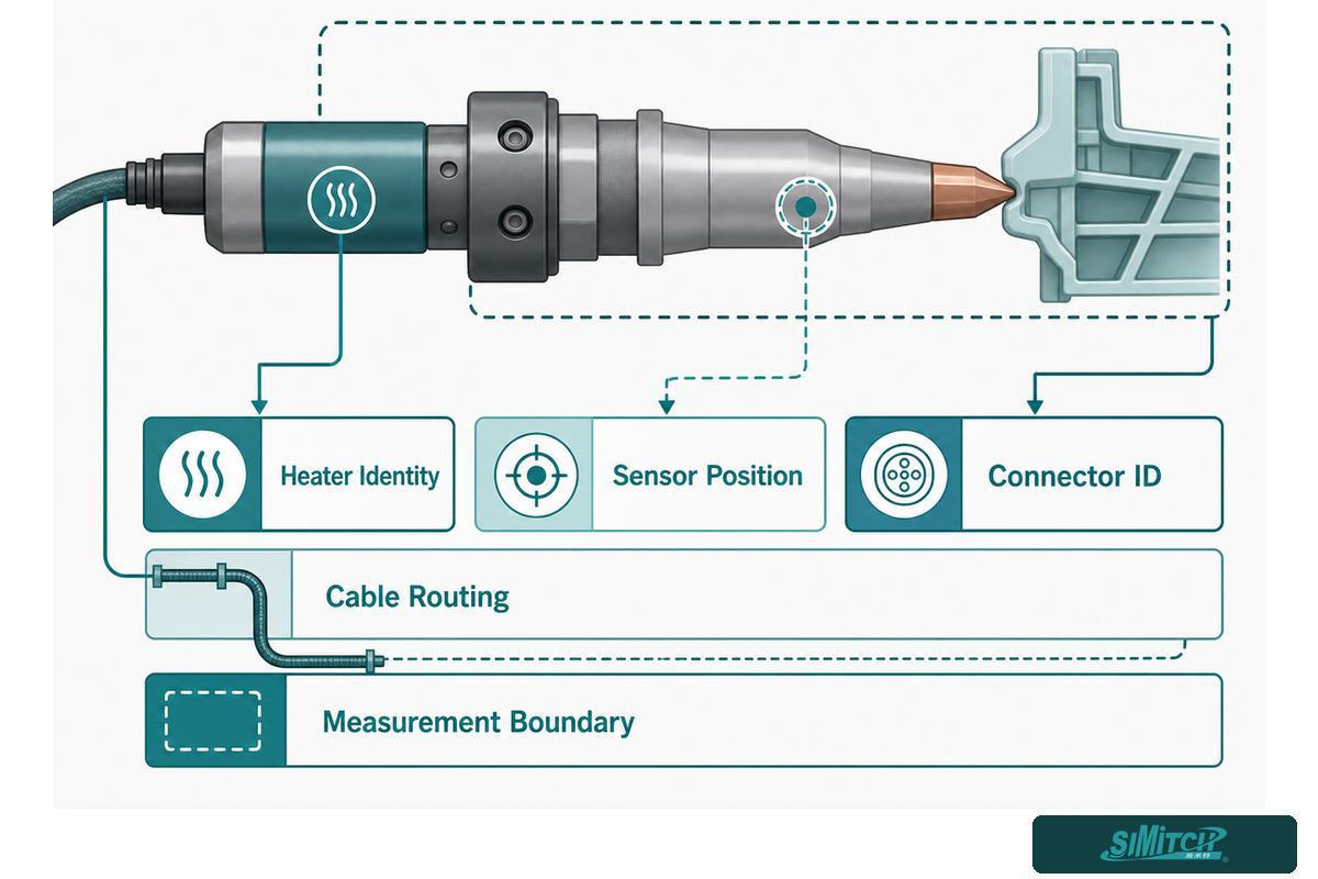
Thermal hardware begins with interfaces: where heat is generated, how it conducts through the head and tip, where it is measured, what insulation separates it from the rest of the fixture, and what happens during idle time or changeover. A displayed controller value is typically a measurement at a chosen sensor location. The problem is measurement ambiguity: comparing two setpoints can hide a different temperature at the actual contact surface.
Record the identity of heater and sensor, sensor position, connector ID, cable routing, and how you intend to observe the stabilization prior to the trial. The intent is for the team to be able to restore the hardware configuration, rather than try to remember the configuration, in case a tip, sensor, or cable is swapped. The patent record in the source set comes into use here as a reminder that the position of the sensor is a design variable.
This section isn’t a recipe. Material behavior, joint geometry, tip mass, contact method, and adjacent components may all impact the thermal response. Trade engineering sources likewise caution against treating cooling behavior as universal. Design review should make the measurement boundary explicit, and send the development of process windows to the validated process workstream.
6. Select tooling materials, surfaces, and replaceable elements by function
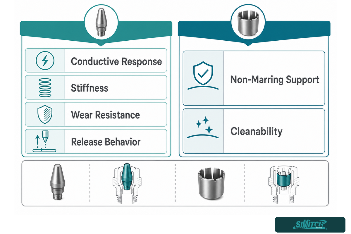
Tooling material selection is a set of tradeoffs, not a list of mandatory alloys or coatings. A staking tip may need conductive response, stiffness, wear resistance, release behavior, and a surface that doesn’t transfer contamination to the assembly. A nest contact may place more importance on non-marring support, cleanability, or controlled compliance. A material that is adequate for a formed feature may be inadequate for a cosmetic locating face.
Consider the failures and what each element touches: tip face, insert, nest pad, clamp surface, guide feature, locating pin, thermal break, sensor, connector, and fastener. Ask whether the element is expected to wear, whether it can be inspected without disturbing critical alignment, and whether replacement requires restoring the tool datum. A replaceable element without a clear identity or restoration method isn’t controlled maintenance; it’s a future variation source.
Keep surface descriptions functional. State the permitted contact face, finish intent, release or cleanability concern, and inspection point. Do not claim that one finish, coating or cooling technique is adequate for all resins. The joint and part definitions own that decision.
7. Write a mold-to-machine interface contract that includes service and safety boundaries
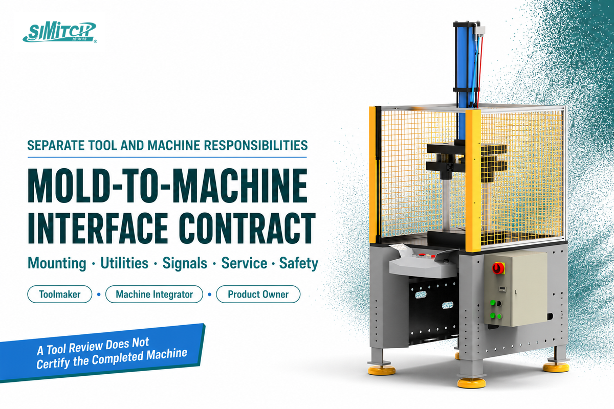
A tooling drawing isn’t enough when another machine, team, or site must integrate it. Therefore, a compact interface contract must separate what the tool offers from what the machine must accommodate. From a mechanical perspective, include mounting face, reference features, head pattern, tool envelope, fastener access, loading direction, clearance for changing parts, and any alignment features. On the electrical and pneumatic side, identify each heater and sensor circuit, connector type, air connection, labeling convention, cable path, and any tool-present or part-present signal requested by the tooling design.
Safety belongs in the contract because tool geometry can create a pinch zone, expose a hot surface, restrict access for maintenance, or retain a form of stored energy. The review should mark those interfaces and make the responsible party visible. It should not state that a mold checklist on its own confirms a machine. OSHA’s general machine-guarding requirements address hazards at the point of operation and around the machine, while its hazardous-energy rule addresses servicing controls. ISO 12100 provides the broader risk-assessment frame. Those sources guide the boundary; the actual safeguard selection and site assessment remain machine- and installation-specific.
A useful responsibility split is: the product owner controls the approved part and joint definition; the toolmaker controls controlled tooling design and identification; the machine builder or integrator confirms the machine-side envelope, utilities, controls, and safeguards. The handoff is complete only when open assumptions have an owner and a disposition.
8. Control revisions, wear parts, and changeover hardware before they become undocumented variables
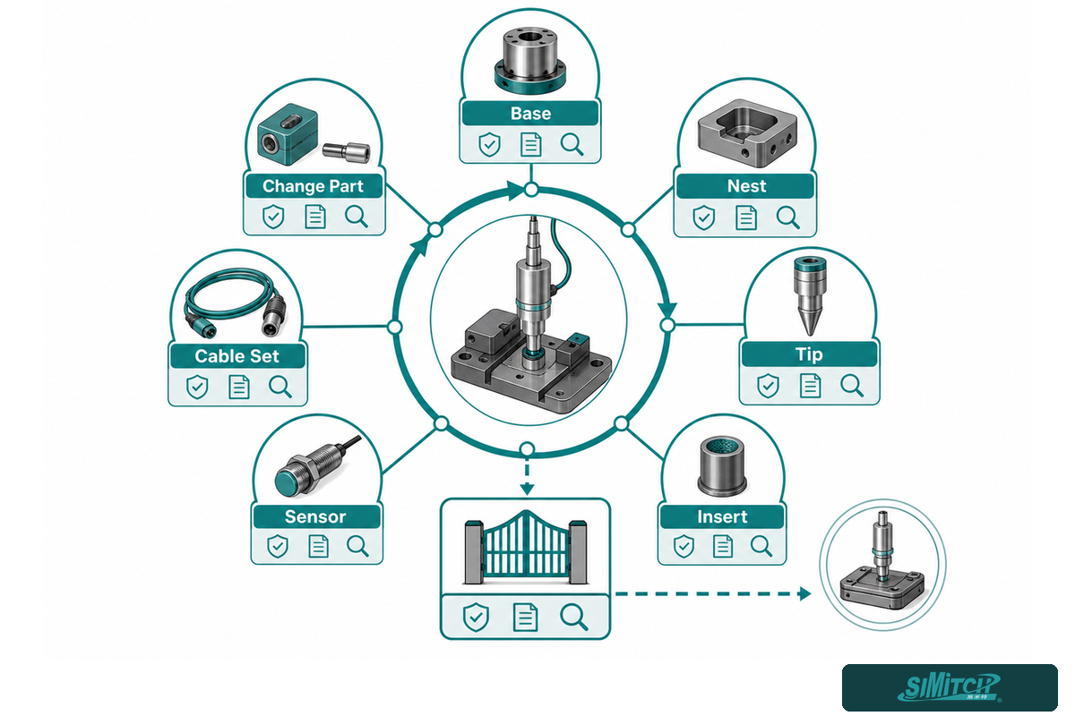
Heat-staking hardware rarely stays static through its whole life. Tips wear, inserts get swapped, sensors get replaced, and a product family adds variants. The control question is whether the tool can return to a known configuration after each event. Assign a unique identifier to the base, nest, tip, insert, sensor, cable set, and change part where the distinction matters. Link these to the controlled assembly drawing and the revision of the drawing which is authorized for the trial or production use.
Tool Revision Ledger
For each change, retain the tool ID, drawing revision, changed component, reason, affected part variants, interface affected, inspection or continuity check required, responsible owner, and disposition before the next trial. A ledger captures the extent of the change; it does not establish a process capability.
For a product family, choose deliberately between a common base with controlled change parts, a dedicated mold, or a pause until the part design stabilizes. A family tool can be efficient only when datums, load path, access, and thermal architecture are genuinely compatible. Do not use interchangeable inserts to mask an unresolved part-revision issue.
9. Run a 12-check pre-trial mold readiness review
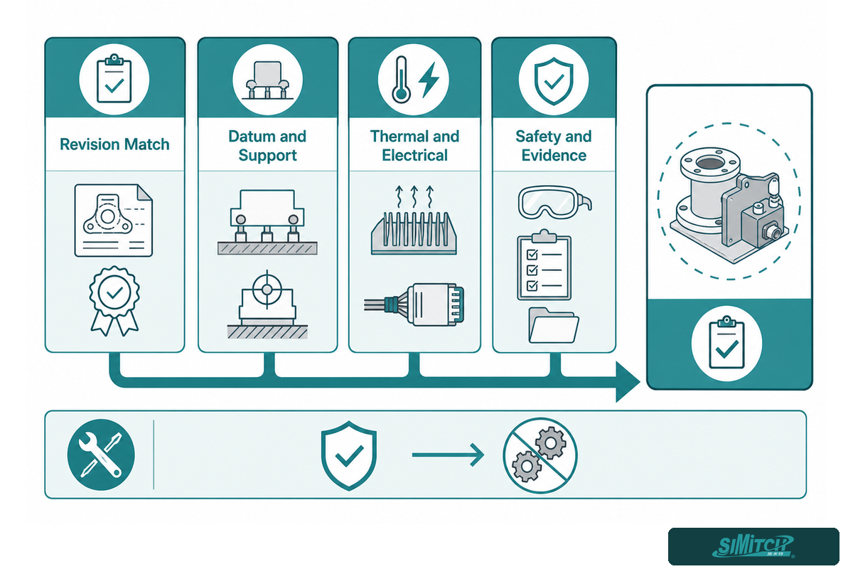
A pre-trial review is a controlled evidence discussion against hardware readiness. It answers whether the tool is coherent enough to enter a representative-part trial; it doesn’t prove a production window, validate a process, or demonstrate long-term capability. Retain the evidence with the current tool revision to avoid an untraceable ‘approved’ status for subsequent changes.
12-Check Pre-Trial Mold Readiness Review
- Controlled part, tool drawing, and revision match are confirmed.
- Critical tool dimensions and component identifiers are recorded.
- Datum location is repeatable and visible in the design basis.
- Support exists beneath the intended forming load path.
- Part loading, tool removal, and fastener access are practical.
- Head parallelism and any intended compliance are defined.
- Heater and sensor circuits are identified and continuity is confirmed.
- Thermal stabilization can be observed at the declared measurement boundary.
- Inserts and change parts return to repeatable locations.
- Sensing and wrong-tool-prevention needs are identified.
- Guarding, hot-surface, and maintenance-clearance interfaces are reviewed.
- Inspection evidence, trial measurements, and disposition rules are retained before the trial starts.
Check 12 is purposely restricted. This step requires agreement on what will be measured and how the result of the trial will be disposed; however, this check won’t inform a team about the settings to establish or the capability threshold to claim. For process-window development and verification, use the separate heat-staking process guide.
The handoff after hardware readiness
When the part, tool, and fixed machine interfaces are defined, the next design conversation belongs with the Hot-Melt Connection Molds & Equipment page. This guide remains limited to the controlled hardware definition and its documented handoff boundaries.
FAQ
Is a heat-staking mold the same as an injection mold?
A heat-staking mold is not an injection mold: it locates, supports, and forms an already-molded assembly rather than creating the original plastic part from molten resin.
No. In this context, a heat-staking mold is the production tool that locates, supports, and helps form an already-molded assembly during heat staking. It may include a nest, tooling plate, staking tips, locating features, and change parts. An injection mold forms the original plastic component from molten resin. Because suppliers use “mold,” “fixture,” “nest,” “tool,” “head,” and “die” differently, define each item by its function, interfaces, and controlled drawing rather than relying on the noun alone.
Can one mold run several plastic-part variants?
One mold can run several plastic-part variants only when their datums, load paths, joint access, head positions, and thermal architecture remain compatible under a controlled change-part strategy.
It can when the variants share a stable datum structure, compatible boss locations, a similar load path, adequate access, and compatible thermal architecture. Interchangeable nests or tips can expand coverage, but every exchange adds setup, identification, sensing, and repeatability risks. Approve a family-tool concept only after each controlled variant has been mapped to common and variant-specific interfaces. If a variant changes a locating face, support condition, or heat-sensitive neighbor, it may need a dedicated change-part strategy or a separate tool.
What files should a heat-staking mold design review start from?
Start a heat-staking mold review with controlled part data, material and joint definitions, datum intent, approved variants, access limits, heat-sensitive features, and the proposed machine-side envelope.
Start with controlled part drawings or approved 3D files, polymer and filler information, boss and mating-part geometry, cosmetic restrictions, nearby heat-sensitive components, approved variants, datum intent, loading orientation, access limits, and the proposed machine-side tool envelope. Add the applicable tooling assembly drawing and revision history if they exist. Record each missing input as an owned assumption, because the purpose of the review is to make incomplete information visible before it turns into conflicting hardware or an unplanned revision.
Should the mold or the equipment be specified first?
Define the joint, datum, support, access, and fixed tooling interfaces first; then confirm that the proposed equipment can accommodate those requirements without forcing unsuitable hardware compromises.
Tool and machine definitions usually converge iteratively. Selecting a press first can impose unsuitable travel, head spacing, mounting, utility, or control constraints that are expensive to correct later.
How is mold acceptance different from process validation?
Mold acceptance checks that controlled hardware matches its design and interfaces correctly; process validation tests whether the complete production process remains capable across approved materials, settings, operators, and conditions.
Mold acceptance confirms that controlled hardware matches its design, locates and supports representative parts, reaches its declared measurement condition, interfaces with the machine, changes over consistently, and retains the agreed records. Process validation goes further: it evaluates whether the full production process remains capable across approved materials, settings, operators, and operating conditions. Appearance alone can’t close that gap because internal defects may remain hidden. A readiness review must not be presented as a substitute for product- and process-specific evidence.
Why this guide stays at the interface level
SIMITCH publishes equipment information, but an effective tooling review starts with the part and its interfaces. This article isolates decisions around heat-staking nests, thermal heads, and machine interfaces so a controlled part definition can reach the correct design, integration, and validation owners. Learn more about SIMITCH or browse the company’s industrial joining guides.
References & Sources
- OSHA 1910.212, General Requirements for All Machines machine-guarding boundary.
- OSHA 1910.147, The Control of Hazardous Energy servicing boundary.
- ISO 12100:2010 Safety of Machinery risk-assessment and risk-reduction framework.
- Peer-reviewed PA12 heat-staking study — scoped evidence that geometry, alignment, material condition, and thermal variables interact.
- US10625474B2 patent disclosure used only for implementation examples of thermal punch and sensor arrangements.
- ASSEMBLY Magazine: Staking for Plastic Parts Assembly — trade coverage of staking methods and tooling variation.
![Hot-Melt Connection Molds & Equipment Guide [2026]](https://simitch.com/wp-content/uploads/2026/09/hot-melt-connection-molds-equipment-guide-featured-150x150.png)


