Get in touch with Suzhou Simitch Machinery Co., Ltd Company

Thermoplastic joining process guide · Updated September 2026
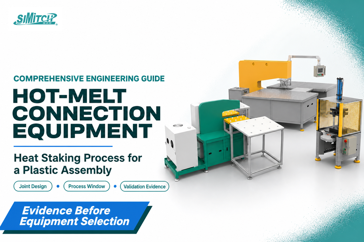
Hot-Melt Connection Equipment is a controlled heat-staking system for forming thermoplastic retaining features. This guide shows how to define the joint, select a joining route, translate material and geometry into equipment controls, screen a process window, and build evidence that survives production change.
In short: in this guide, hot-melt connection equipment means a controlled heat-staking system that warms and reforms a thermoplastic boss to retain a mating component. It is not a hot-melt adhesive melter, a flow-drill screwdriving cell, or PE-pipe butt-fusion equipment. The right system begins with a measurable joint requirement and ends with a qualified process record—not a copied temperature or one attractive sample.
The phrase creates a real search-language problem. “Hot melt” often describes adhesive dispensing. SIMITCH also uses the broader commercial family to discuss FDS and thermoplastic staking, while pipework engineers may be looking for heat-fusion equipment governed by a different process family. ISO 21307, for example, addresses PE-pipe butt-fusion procedures, equipment, and completed-joint quality assessment. This article stays with moulded-component thermoplastic heat staking.
If you are comparing machine architectures, automation options, project configuration, or quotation requirements, use the hot-melt connection equipment and system options page. The guide below has a different job: it helps design, quality, manufacturing, and procurement teams create the evidence package that should drive that commercial conversation.
Scope note: The tables presented here serve as planning guides, not universally applicable recipes, legal interpretations, qualified thermal joining processes, or a substitute for material manufacturer data sheets, the appropriate equipment manual, a site risk assessment or site-specific validation requirements.
1 · Define
Load, movement, appearance, environment, life, and evidence
Load, movement, appearance, environment, life, and evidence
2 · Translate
Resin and boss geometry into thermal and mechanical controls
Resin and boss geometry into thermal and mechanical controls
3 · Demonstrate
Boundaries, repeatability, destructive tests, and durability
Boundaries, repeatability, destructive tests, and durability
4 · Sustain
Monitoring, maintenance, safety, and change control
Monitoring, maintenance, safety, and change control
1. How Heat Staking Works in Hot-Melt Connection Equipment
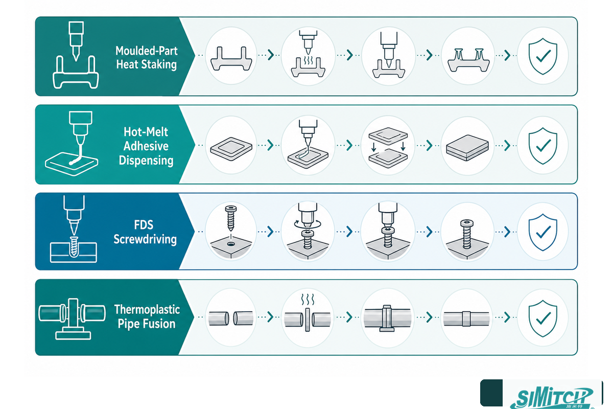
Within the process boundary defined above, heat staking works by locally heating a thermoplastic feature, forming it over or through a mating component, and controlling cooling or release so the enlarged head mechanically retains the assembly. The mating part may be metal, plastic, a PCB, fabric, or another material that does not itself need to melt. AMADA Weld Tech and Emerson Branson describe this localized heat-form-cool principle in their technical overviews.
| Route | Primary mechanism | Typical output | Do not transfer |
|---|---|---|---|
| Moulded-part heat staking | Heat and reform a thermoplastic boss | Enlarged retaining head | Adhesive temperature or pipe-fusion recipe |
| Hot-melt adhesive dispensing | Melt, meter, and apply an adhesive | Bond line | Thermode force or boss geometry rules |
| FDS screwdriving | Frictional heat plus flow drilling and fastening | Threaded mechanical joint | Plastic-stake dwell or cooling logic |
| Thermoplastic pipe fusion | Heat and fuse pipe or fitting interfaces | Continuous fused joint | Moulded-boss tooling or acceptance rules |
This distinction protects the project from a surprisingly common failure: selecting a machine name first and forcing the part into the wrong joining physics. Once the route is correct, the remaining work is to convert joint risk into controlled variables and acceptance evidence.
Heat staking appears in automotive electronics, medical devices, consumer housings, and EV battery modules when a moulded feature can retain another part. In these heat staking applications, heat staking joins dissimilar materials through a mechanical head rather than a chemical bond. Engineers may join plastic to metal, plastic to plastic, or retain a printed circuit board within a plastic assembly. These examples describe possible part stacks, not automatic suitability.
2. Heat Staking Applications: Choose the Joining Route Before the Equipment
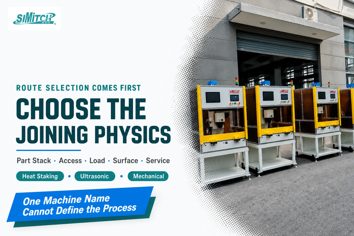
Choose a route by the part stack, load case, access, surface risk, service strategy, and proof method. Heat staking is attractive when a moulded boss can mechanically retain a dissimilar component without transmitting the vibration used by ultrasonic methods. That does not make it universally better; access, takt time, material response, head appearance, particulates, and rework can reverse the decision. The SIMITCH joining-route matrix can help structure that comparison.
| Route | Good starting fit | Main constraint to prove | Next evidence |
|---|---|---|---|
| Contact thermode staking | Accessible boss and controlled tool contact | Sticking, marking, heat transfer | Contact, temperature, force, release trials |
| Hot-air/cold-tool staking | Separate heating and forming access | Airflow, shielding, heat spread | Thermal map and melt-front evidence |
| Pulse/electrical staking | Fast local thermal response | Sensor location and release control | Actual energy/temperature and cycle trace |
| Infrared staking | Non-contact preheat and optical access | Absorption, color, shielding | Part-specific thermal distribution |
| Ultrasonic staking | Fast localized forming | Vibration path, horn access, cosmetics | Amplitude/force trials and damage review |
| Hot-plate welding | Two compatible thermoplastic interfaces | Plate access, melt displacement, flash | Weld-section and strength trials |
| Mechanical fastener | Serviceable or reversible assembly | Boss stress, loosening, hardware | Torque, pull-out, vibration evidence |
| FDS | One-sided metal joining | Heat, torque, stack access, thread formation | Fastener and metal-stack process trial |
| Adhesive dispensing | Bond-line sealing or distributed load | Surface, cure/set, bond-line control | Material compatibility and aged bond tests |
Route screening eliminates obvious mismatches; it does not approve the process. Run the remaining candidates against the same acceptance criteria, including the same surface class, service loads, environmental exposures, cycle requirement, and inspection burden.
Heat staking uses heat and pressure in a controlled local forming sequence without requiring the vibration delivered by an ultrasonic horn, so heat staking avoids that specific process vibration. It does not follow that staking eliminates all vibration, particles, cosmetic risk, or collateral heating in the finished machine.
3. Freeze the Plastic Assembly Requirements Before Setting Temperature
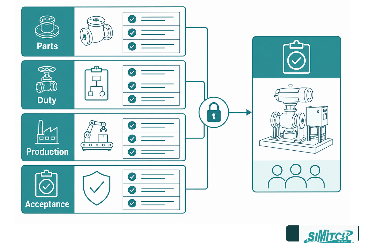
Once the joining route is chosen, “strong enough” cannot guide tool design or approve a trial. Replace it with a joint requirement record: load direction and magnitude, allowed movement, cosmetic class, service temperature, humidity or chemical exposure, expected life, rework policy, takt time, traceability, inspection frequency, and the failure modes the test must expose.
Joint Requirement Record
Freeze one revision-controlled record before supplier trials.
- Parts: drawings, revisions, resin grade, filler, pigment, mould cavity, moisture history, mating material, and representative samples.
- Duty: load direction, peak and sustained load, movement limit, service life, environment, visible-surface class, and disassembly intent.
- Production: takt time, changeover, traceability, data retention, operator touchpoints, planned maintenance, and utilities.
- Acceptance: visual limits, dimensions, destructive or non-destructive tests, sample logic, durability exposures, decision owner, and deviation route.
15-Field Measurement Definition Matrix
Engineering note: agree the unit, range, resolution, sampling rate, and instrument before a trial. The values below are recording-format examples, not machine specifications, process limits, or acceptance criteria. For example, a draft data schema might record temperature to 1 °C, force to 1 N, and displacement to 0.01 mm; the project must justify its own ranges and measurement capability.
| Measurement type | Example recording resolution | Boundary to define |
|---|---|---|
| Boss and head geometry | 0.01 mm input, 0.01 mm output, 0.1 mm location | Gauge method, datum, temperature, and operator |
| Tool and part position | 0.01 mm command, 0.01 mm actual, 0.1 mm fixture check | Measurement point, compliance, zero, and backlash |
| Temperature | 1 °C command, 0.1 °C sensor, 1 °C report | Sensor type, location, response, and calibration |
| Force | 1 N command, 0.1 N sensor, 1 N report | Load path, tare, peak, curve, and overload |
| Time | 0.01 s heat, 0.01 s dwell, 0.01 s cool | Start/stop event and controller timestamp |
| Delivered energy | 0.1 J command, 0.1 J measured, 1 J report | Electrical boundary, losses, and calculation method |
| Air supply | 0.1 bar pressure, 1 L/min flow, 1 °C temperature | Supply versus delivered condition and restriction |
| Mechanical test | 1 N load, 0.01 mm movement, 1 mm/min rate | Fixture, direction, preload, rate, and failure code |
| Torque test | 0.01 N·m torque, 1 deg angle, 1 deg/s rate | Axis, grip, preload, and end condition |
| Production rate | 1 part/min cycle, 1 min changeover, 1 hr peak window | Released output, rejects, rework, and buffers |
| Calculated stress | 0.1 MPa input, 0.1 MPa output, 1 MPa report | Area definition, model assumptions, and test correlation |
| Vibration exposure | 1 Hz input, 0.1 Hz response, 10 Hz report band | Profile, amplitude, axis, fixture, and duration |
| Electrical demand | 0.1 kW standby, 0.1 kW cycle, 1 kWh batch | Measurement boundary, warm-up, and auxiliary loads |
| Part and fixture mass | 0.01 kg part, 0.1 kg nest, 1 kg assembly | Tare, handling condition, and supported mass |
| Environmental exposure | Illustrative 1 percentage-point humidity step, 1 °C chamber, 24 h dwell | Conditioning, ramp, stabilization, and recovery |
The acceptance method should follow the expected failure. A retaining head loaded in pull-out may need a different fixture and metric from one loaded in shear or torque. A cosmetic cover may be rejected for sink or witness marks long before mechanical retention is threatened. A joint exposed to heat and sustained load may pass an immediate pull test yet fail by creep later. Those are different decisions and need different evidence.
4. Material, Boss Geometry, and Heat Staking Design Guidelines
The machine does not process “plastic” in the abstract. Resin grade, reinforcement, pigment, moisture history, recycled content, moulding condition, and lot can change heat transfer and forming response. Boss height, wall thickness, available head volume, hole clearance, unsupported span, tool clearance, and fixture support determine where material can flow and where loads travel.
For practical boss design, identify the mold cavity and the actual plastic boss rather than applying generic design guidelines. Polycarbonate and glass-filled materials, for example, can respond differently from an unfilled grade; the orientation and content of glass fibers also belong in the material record. Knurled or otherwise textured features may change joint geometry and flow, but they are not universal design rules. When staking plastic parts, the approved drawing and material evidence govern.
The mechanical idea is simple: the boss passes through a mating feature and its exposed volume is reformed into a head larger than the opening. A patent record can illustrate that mechanism, but it cannot supply a universal boss ratio or acceptance value. Geometry rules must be tested with the actual resin, moulded condition, mating stack, load, and forming route. For project-specific tooling scope, see SIMITCH’s hot-melt connection molds; do not treat a tooling example as a universal geometry rule.
Engineering note: treat colour or filler changes as process changes until evidence shows otherwise. They can alter absorption, thermal conductivity, melt behaviour, stiffness, and surface appearance. Recipes proven on an unfilled natural resin should not be silently released for a pigmented glass-filled grade.
As heat is applied, the polymer does not soften everywhere at once. The temperature relative to the material’s glass transition temperature or melting behaviour, the heat path, and time determine where softened plastic can flow. The tool forms that volume, and the plastic cools under a defined support or release condition. That sequence explains why heat staking design must link material, geometry, heat, force, and cooling.
5. The Joint-to-Heat Budget Map
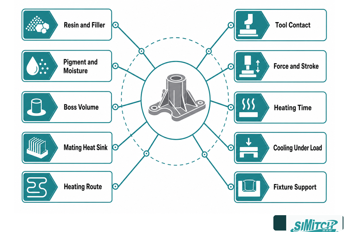
The Joint-to-Heat Budget Map translates design parameters to trial parameters and evidence, not to one magical setting. It asks where heat should go, which dimensional requirements must remain stable, how the fixture supports forming force, and which signal confirms the intended state.
| Input | If under-controlled | Trial variable | Observable signal | Acceptance evidence |
|---|---|---|---|---|
| Resin and filler | Wrong softening or degradation response | Heating mode, rate, dwell | Actual temperature/energy, colour, surface | Material-specific window and test |
| Pigment and moisture | Lot-to-lot thermal or cosmetic drift | Conditioning and energy | Lot ID, moisture control, appearance | Worst-case lot comparison |
| Boss volume | Incomplete head or excess flash | Tool cavity, end position | Head height/diameter, displacement | Drawing limits plus retention test |
| Mating heat sink | Cold interface or collateral heating | Heat direction, shielding, preheat | Thermal map near the stack | No damage plus formed geometry |
| Heating route | Different melt depth or cycle response | Contact, air, electrical, or IR input | Delivered energy and part temperature | Route-specific qualified range |
| Tool contact | Uneven forming, sticking, witness marks | Face geometry, finish, alignment | Contact pattern and release condition | Head map across all stations |
| Force and stroke | Poor consolidation or part distortion | Force curve, speed, end position | Force-displacement trace | Trace limits correlated to joint tests |
| Heating time | Core remains solid or heat spreads too far | Time and rate | Thermal history and displacement onset | Bounded response at both edges |
| Cooling under load | Spring-back, sticking, slow release | Cooling route, time, release point | Release force and head recovery | Stable dimension after conditioning |
| Fixture support | Tilt, sink, stress, inconsistent end position | Support position and compliance | Part movement and head angle | All-cavity dimensional evidence |
Research validates the map’s multi-factor logic, not an application-ready recipe. In 2018, an experiment with PA6-GF30 and a brass insert explored heating temperature and insertion time via factorial and response-surface methods. In that case, the factors and their interaction mattered, with temperature dominant for insertion height. Its tested ranges are not your part’s.
Separate polypropylene hot-air research monitored melt progressing from the outside to the pin core as heating time grew. Again, the transferable lesson is the progression: heating method, geometry, time, and material interact to shape the melt field. This paper’s lab configurations are not recommended for production.
6. Specify the Heat Staking Technology, Machine, and Equipment Stack
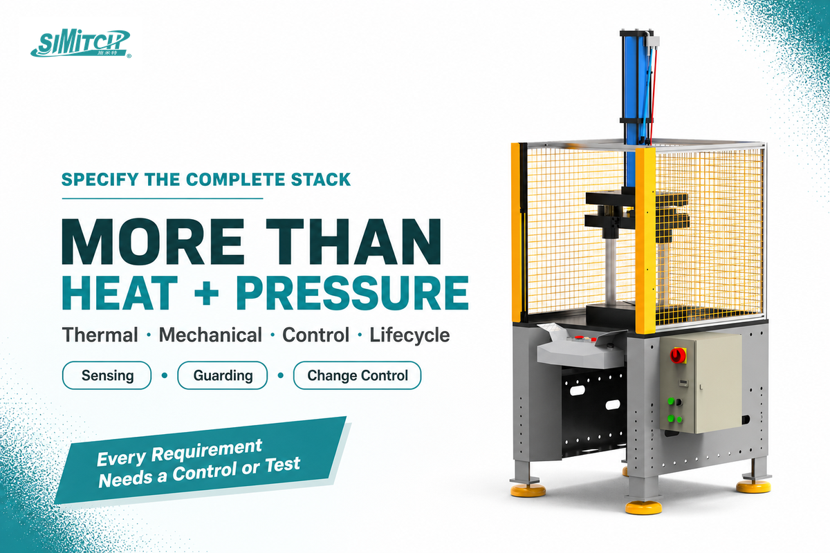
In practice, pairing a heater with a press does not create a production-ready heat-staking solution. The preceding Joint-to-Heat Budget Map identifies what the equipment stack must control. Control each energy source, tool, actuator, support structure, fixture, sequence, measurement, and hazard mitigation as one process. Detailed supplier communication links each joint requirement to either a controlled input, a measured output, or an approved offline test.
A heat staking machine may use electrical heating, infrared energy, hot air supplied through compressed-air controls, or another validated route. Whatever the staking technology, define the heat control, process control, and process parameters that produce consistent head formation without damaging the downstream assembly. “High-frequency” is not a synonym for every thermal staking method, and heat staking solutions should be compared by measured process capability rather than labels. When force-displacement monitoring is part of the evidence plan, review the relevant servo press system options against the actual joint requirements.
Thermal
Heat source, delivery route, tool, local sensing, shielding, and cooling
Heat source, delivery route, tool, local sensing, shielding, and cooling
Mechanical
Actuator, force, stroke, speed, end position, fixture, and support
Actuator, force, stroke, speed, end position, fixture, and support
Control
Recipe revision, limits, trace, alarms, reject handling, and part identity
Recipe revision, limits, trace, alarms, reject handling, and part identity
Lifecycle
Guarding, extraction, maintenance access, calibration, spares, and change control
Guarding, extraction, maintenance access, calibration, spares, and change control
In-situ sensing needs careful definition. The proximity sensor at the forming interface may give a different answer than the heater-zone controller. In the same vein, commanded force or position may not equate to force or displacement delivered at the boss. Specify where, how, and how well each signal is measured and calibrated, and how it aligns with joint evidence.
Discuss a part and process-evidence package
7. The Five-Condition Process-Window Screen
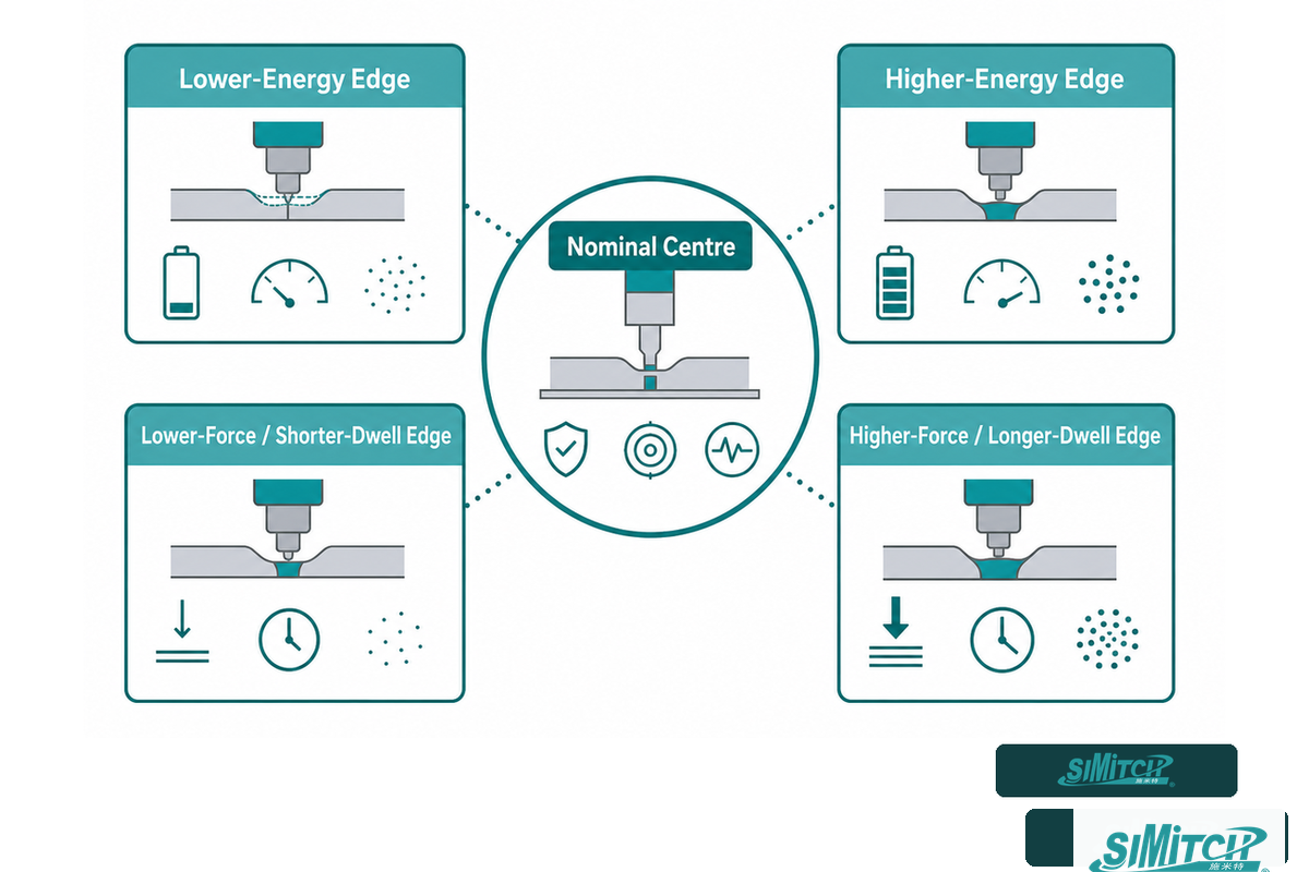
In practice, the Five-Condition Process-Window Screen is an exploratory worksheet, not a five-sample qualification. With the equipment stack defined, the screen challenges its controllable inputs at a centre point and four edges. Each condition requires sufficient replicates to reveal repeatability; define the aggregate sample size from expected variation, desired accuracy, the shift or defect the study must detect, and the risks of false acceptance or rejection.
| Condition | Question | Hold constant | Record | Escalation |
|---|---|---|---|---|
| Nominal centre | Does the planned centre create the intended head and load response? | Part lot, geometry, fixture, tool, test | Actual energy/temperature, force, displacement, time, dimensions, test | No edge work until the mechanism is understood |
| Lower-energy edge | Where does incomplete softening or forming begin? | Everything except the declared energy challenge | Unformed volume, trace, gap, head dimension, load result | If failure mode changes, redesign the study |
| Higher-energy edge | Where do flash, sticking, marking, or degradation risk appear? | Same controlled baseline | Surface, release, dimension, thermal evidence, load result | Contain before expanding the range |
| Lower-force/shorter-dwell edge | Is material softened but insufficiently formed or stabilized? | Thermal condition and part inputs | Force-displacement curve, spring-back, dimensions, test | Separate force and time if interaction is unclear |
| Higher-force/longer-dwell edge | Does extra forming or cooling improve retention or damage the stack? | Thermal condition and part inputs | Part deformation, sink, head recovery, cycle time, test | Stop if the failure shifts into the base part |
NIST’s statistical references are direct about the “how many samples?” concern: absent assumptions about intrinsic variation, error risks, and the shift or accuracy the study should detect, there is no ideal sample count. Five conditions indicate where to search; they do not specify how many parts validate the window.
ISO 23512:2021 provides the more relevant qualification boundary. Use this screen to plan your discovery and produce a site-applicable TJPS, designed experiments (DOE), gage work, capability proof, durability plan, and customer qualification.
8. Validate the Joint With More Than Appearance
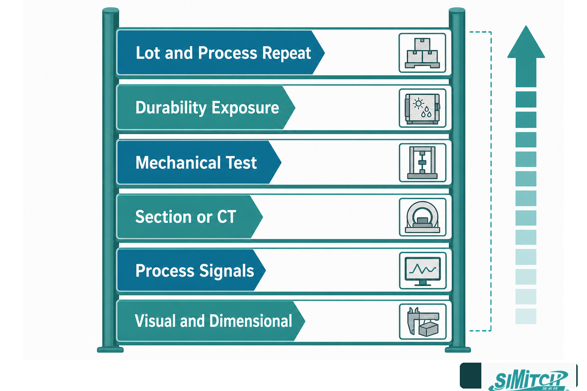
That distinction matters: appearance can reject an obvious defect, but it cannot prove internal structure, retained strength, or service life. The five-condition screen shows where to challenge the process; this evidence ladder determines what each challenge must prove. Build an evidence ladder from the failure mode backward: defined visual limits, head dimensions, process trace, sections or CT when justified, destructive load or torque tests, material-lot repeats, and the environmental exposures that represent the application.
| Layer | Answers | Does not answer alone |
|---|---|---|
| Visual and dimensional | Was the head formed within defined external limits? | Internal voids, molecular damage, retained load |
| Process signals | Did measured energy, force, displacement, and time stay in their ranges? | Joint quality unless correlation is demonstrated |
| Section or CT | What internal flow, contact, porosity, or damage is present? | Population performance without a sampling plan |
| Mechanical test | How does the defined joint fail under the stated load fixture and rate? | Service life outside the test condition |
| Durability exposure | Does retention survive relevant creep, thermal cycling, humidity, chemicals, or vibration? | Unrepresented field conditions |
| Lot and process repeat | Is the result reliable across legitimate material and production variation? | Future unapproved changes |
A 2026 PA12 study combined tensile tests, microsections, and micro-CT to examine how processing and local structure relate to joint performance. Its reported strength belongs to its SLS and turned specimens, geometry, settings, and test method. The useful transfer is the evidence strategy: surface, internal structure, and mechanical behaviour answer different questions.
The release record should identify part and drawing revision, resin and lot, mould cavity, tool and fixture revision, equipment ID, recipe revision, measurement method, sample plan, every result, deviations, rework, remaining limitations, and approvers. Without that context, a “passed” photograph or force value cannot be replayed after a change.
9. The Stake-Head Evidence Matrix
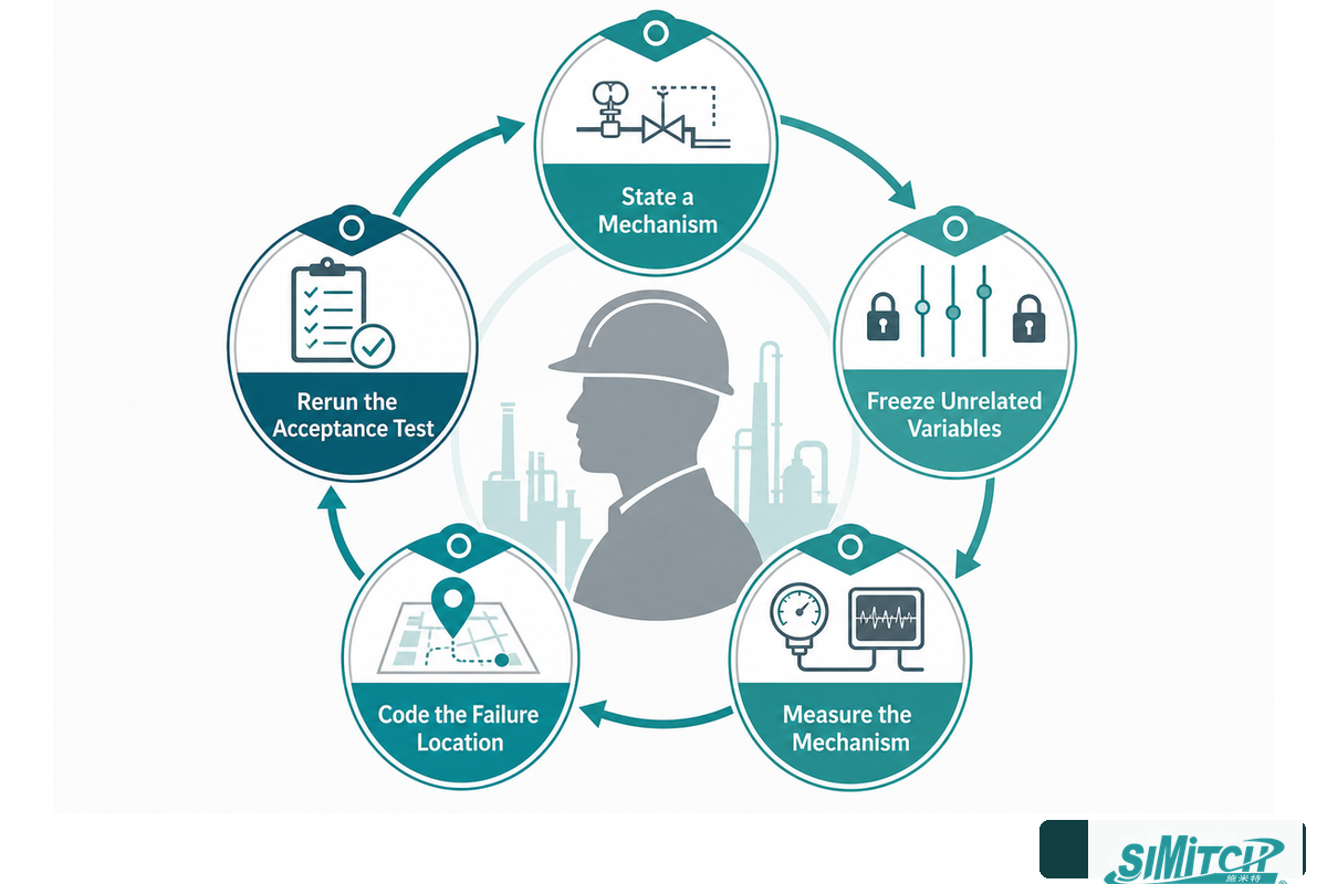
The Stake-Head Evidence Matrix prevents symptom-based tuning. A visual clue should start a hypothesis, not finish a root-cause analysis. Hold the part and baseline stable, measure the suspected mechanism, contain affected product, and release a correction only after the evidence changes as predicted.
Most heat staking failures are not diagnosed by one photograph. Tool sticking may involve release temperature or surface condition; an incomplete head may involve energy, force, boss volume, or obstruction. The matrix keeps these alternatives open until measurements separate them.
| Symptom | Plausible mechanism, not a verdict | Next measurement | Containment | Release evidence |
|---|---|---|---|---|
| Incomplete head | Low delivered energy, short dwell, low force, excess volume, or obstruction | Actual thermal history, force-displacement, boss volume | Hold affected cavity/recipe | Edge trials plus dimensional and load result |
| Excess flash | High energy, excess boss volume, tool cavity mismatch, or over-travel | Boss dimensions, end position, thermal trace, tool condition | Segregate out-of-limit heads | Stable geometry without hidden retention loss |
| Fuzzy or stringy surface | Material behaviour, overheating, moisture, sticking, or release timing | Lot/moisture record, temperature, release force, tool face | Stop uncontrolled recipe changes | Material-specific repeat and correlated strength |
| Crack | Cold forming, excessive strain, geometry notch, brittle material, or fixture stress | Section, thermal evidence, boss geometry, support movement | Reject cracked joints | Section and mechanical/durability confirmation |
| Discolouration | Overheating, residence, contamination, pigment response, or tool residue | Actual thermal history, material lot, residue inspection | Hold until degradation risk is resolved | Material review plus stable edge evidence |
| Tilted head | Misalignment, uneven heating, boss variation, or fixture compliance | Alignment map, cavity data, contact and support movement | Separate affected station/cavity | All-position dimensional and load evidence |
| Tool sticking | Release too hot, residue, face damage, material adhesion, or cooling restriction | Release temperature/force, cooling flow, face condition | Prevent manual unsafe release | Clean repeat release across the window |
| Loose mating part | Head/gap geometry, spring-back, stack variation, or insufficient retention | Gap, head dimensions, clamp/play test, load result | Hold the assembly family | Movement and load limits across variation |
| Dimension drift | Tool wear, sensor drift, fixture heat, part lot, or cooling change | Time series by station, lot, tool life, calibration | Contain from last verified check | Restored stable trend and product evidence |
| Strength scatter | Mixed failure modes, measurement error, material/cavity variation, or unstable process | Failure-location coding, MSA, stratified trace and lot data | Do not average away subgroups | Stable process plus justified capability evidence |
Troubleshooting discipline
Do: state a mechanism, freeze unrelated variables, measure the mechanism, code the failure location, and rerun the applicable acceptance test. Do not: increase temperature from appearance alone, change heat/force/time together, discard failed trials, or release a cosmetic improvement without checking retention and durability.
10. Heat Staking Process Control, Maintenance, Safety, and Change Control
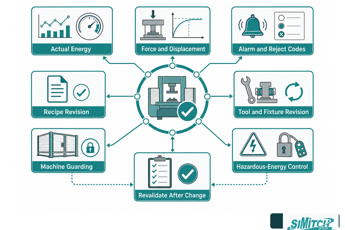
Production control depends on physical evidence. Depending on the joining route, record actual temperature or delivered energy, force and displacement, heating, dwell, and cooling times, alarm and reject codes, station and part identity, material lot, recipe revision, and critical tool or fixture revision.
Maintenance should trend thermode wear and buildup, alignment, fixture support, air or cooling restriction, sensor calibration, wiring or hose condition, and repeated operator intervention. If cleaning, release, adjustment, or reset frequency rises, treat that as process drift. Do not normalize hidden work that keeps the cycle apparently running.
Safety needs separate layers. OSHA 1910.212 is a U.S. point-of-operation guarding boundary: special hand tools supplement rather than replace required guarding. OSHA 1910.147 separately addresses hazardous-energy control during servicing and maintenance when unexpected energization, startup, or stored-energy release can injure employees. Neither text is a machine-specific compliance certificate or a substitute for the installed site’s assessment and procedure.
Heating polymers also creates a material-dependent industrial-hygiene question. A NIOSH investigation of plastic heat-sealing operations detected volatile compounds and documented symptoms, but that process and its materials are not equivalent to every heat-staking cell. The defensible action is to review resin safety information, decomposition conditions, temperature excursions, capture or extraction, and actual exposure with competent EHS support—not to assume either zero emissions or the same exposure profile.
For global projects, apply the destination market’s current machinery rules. The official corrigendum sets 20 January 2027 as the general application date for EU Regulation 2023/1230. Requirements, transition provisions, conformity routes, documentation, and hazardous-substance controls need a competent project-specific review.
Revalidate after a change to resin supplier, grade, filler, pigment, recycled content, moisture control, boss or mating geometry, mould cavity, tool face, fixture, heating route, cooling, sensor, software, acceptance method, or supplier-controlled component that can move a qualified variable. The change record should state which evidence remains valid, what must be repeated, and who accepts the residual risk.
11. From Part Drawing to Qualified Cell: The Eight-Step Handoff
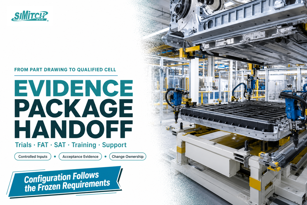
A useful equipment handoff is an evidence package, not a cycle-time target and a CAD file. That package consolidates the production controls and change triggers established above. Use the following sequence to keep route selection, process discovery, qualification, and supplier configuration in the correct order.
- Classify the joining route. Exclude adhesive, FDS, pipe fusion, welding, or fastening routes that do not match the stack and service need.
- Freeze the joint requirement. Define load, movement, appearance, environment, life, takt, traceability, tests, limits, and owners.
- Review material and geometry. Name the actual resin, legitimate variation, boss volume, mating feature, tool access, and fixture support.
- Specify the complete equipment stack. Map every requirement to heat, forming, support, cooling, sensing, data, guarding, extraction, and maintenance access.
- Screen a bounded process space. Use deliberate centre and edge conditions with justified replicates; retain all failures and interactions.
- Qualify the process and joint. Establish essential variables and ranges, measurement capability, internal and mechanical evidence, durability, and customer requirements.
- Lock production monitoring and change control. Correlate signals, set reaction plans, control recipes, and define revalidation triggers.
- Send the evidence package to the supplier. Configuration, trials, FAT/SAT, manuals, training, spares, and support should respond to the same frozen package.
The company background and industrial joining focus are available on the About SIMITCH page. Project suitability still depends on the actual parts, acceptance plan, destination requirements, and validated process evidence.
Frequently Asked Questions
What equipment is used for heat staking?
A production heat-staking cell normally combines a controlled heat source, a shaped forming tool or thermode, an actuator, a part fixture, a cooling method, machine controls, and appropriate guarding. Higher-assurance applications may also record actual temperature or delivered energy, force, displacement, cycle time, alarms, and part identity. The exact stack depends on the resin, boss geometry, access, acceptance test, risk, and required production rate.
Buyers should also define extraction, utilities, calibration, tool-life monitoring, recipe access, data retention, reject handling, safe maintenance access, and the hazardous-energy boundary. Each subsystem should trace back to a joint requirement or a verified production-control need.
What temperature do you heat stake plastic at?
No universal safe heat-staking temperature exists for every thermoplastic. The usable range depends on resin grade, filler, pigment, moisture history, boss geometry, heating route, tool contact, time, force, and cooling. Begin with material guidance and controlled equipment trials using real parts.
Then establish qualified ranges for production. A nominal temperature and one visually acceptable sample are not enough to release the process.
Heat staking vs ultrasonic welding: which is better?
Neither process is universally better. Heat staking often suits a moulded boss that must retain a dissimilar component where transmitted vibration or particulate risk matters. Ultrasonic staking can offer fast cycles, but horn access, vibration paths, material response, and cosmetic sensitivity require review.
Compare both routes against the same load case, visible-surface requirement, takt time, inspection plan, durability exposure, and change-control burden.
Can a heat-staked plastic joint be taken apart?
A formed stake is usually a permanent mechanical lock. Removing its head can damage the boss and prevent reuse. If planned disassembly matters, treat it as a design input from the start and choose a reversible fastener or add a serviceable secondary feature.
Can a degraded heat-staked joint be detected visually?
Visual inspection can find incomplete forming, flash, cracks, discoloration, tilt, or tool marks, but it cannot directly prove internal structure, retained strength, or service life. A defensible acceptance plan correlates defined visual limits with head dimensions and process signals, then adds sectioning or CT, destructive tests, durability exposures, and material-lot repeats where risk requires them. Production teams should treat such observations as screening evidence rather than a standalone release decision.
If the study establishes a reliable relationship between a visible feature and a defined failure mode, production teams may use that feature as one screening input; the correlation and its limits still belong in the approved validation record.
References & Sources
- ISO 23512:2021, Specification of variables for thermal joining processes
- ISO 21307:2017, PE piping butt-fusion procedures and quality assessment
- ISO 12100:2010, Safety of machinery, risk assessment and risk reduction
- NIST/SEMATECH e-Handbook – Sample requirements for statistical analysis
- OSHA 29 CFR 1910.212, General machine guarding
- OSHA 29 CFR 1910.147, Control of hazardous energy
- NIOSH HHE 2014-0111-3280 – Heat sealing exposure survey
- EUR-Lex – Corrigendum to Regulation (EU) 2023/1230
- Faria Neto et al. – Heat-staking variable experimental analysis
- Härtel et al. – Hot-air heat-staking experimental and modeling analysis
- Kuettner et al. – Heat-staking microstructure study for PA12