Get in touch with Suzhou Simitch Machinery Co., Ltd Company

POP Rivets Sizes Chart: Blind Rivet Diameters, Grip Range, Drill Hole Size and Load Limits


Pop rivets have sizes specified independently by two measurements: the nominal diameter of the tubular rivet body and the material grip range (the combined thickness of the sheets being joined), as opposed to the overall length of the un-installed shell. Standard industrial blind rivets cover diameters from 3/32” (2.4 mm; trade size #3) to 1/4” (6.4 mm; trade size #8) and require a drilled hole 0.1 mm to 0.2 mm larger than the rivet shank.
Selecting the correct size of blind fastener requires matching four mechanical variables at once: hole clearance, total stack thickness, head bearing area, and single-shear or tensile breaking load. Because blind rivets are perfect for single-sided sheet metal assembly where the back of the joint is unreachable, ordering a standard rivet by body length alone without verifying the catalog grip range is the leading cause of loose joints and incomplete blind-side locking bulbs in fabrication, as documented in Bolt Depot’s blind rivet sizing reference and ISO/TC 2/SC 12 fastener standards (ISO 15977 through ISO 15983).
How Are POP Rivets Sizes Measured Across Diameter, Length and Grip?
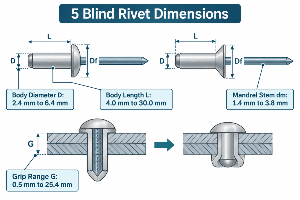
Blind pop rivets are measured across five distinct geometric dimensions: nominal body diameter (D), under-head body length (L), material grip range (G), head flange diameter (Df), and mandrel stem diameter (dm). For standard industrial series governed by IFI-114 and ISO 15977, body diameter spans 3/32 inch (2.4 mm) to 1/4 inch (6.4 mm), while body length must exceed the clamped sheet thickness by enough tail allowance to roll a locking bulb on the blind side.
When engineers evaluate different types of industrial rivets and their structural applications, the biggest measurement trap lies in how rivet length is defined across head styles. On a standard dome-head or large-flange blind rivet, the length of the rivet (L) is measured from the bottom of the flange collar to the end of the tubular sleeve; the head sits on top of the sheet and does not enter the hole. On a 120-degree countersunk blind rivet, length is measured from the flat top of the head to the tail of the rivet body, because the head seats completely within the chamfer of the top sheet.
| Dimension Symbol | Engineering Term | Where to Measure with Calipers | Typical Industrial Span | Selection Role |
|---|---|---|---|---|
| D | Rivet body diameter (shank diameter) | Outside diameter of the un-deformed cylindrical sleeve | 3/32 in to 1/4 in (2.4 mm to 6.4 mm) | Sets drill size and shear load capacity |
| G (Gmin–Gmax) | Grip range (grip length) | Combined thickness of all sheets, coatings, and shims | 0.5 mm to 25.4 mm (1/32 in to 1.0 in) | Primary catalog ordering dimension for clamping |
| L | Rivet body length | Under flange to tail end (dome/large flange) or overall flush length (countersunk) | 4.0 mm to 30.0 mm (0.157 in to 1.18 in) | Determines blind-side clearance required before pulling |
| Df | Rivet head (flange) diameter | Outer diameter of the preformed factory head | approx. 2.0D (dome) or 3.0D (large flange) | Controls pull-through resistance on thin or soft sheets |
| dm | Mandrel stem diameter | Outside diameter of the protruding pull stem | 1.4 mm to 3.8 mm (0.055 in to 0.150 in) | Matches the nosepiece jaw bore of the rivet gun |
Never confuse the portion of the rivet that’s seated in the hole, prior to being set, with the thickness of the material it can clamp. As noted in the STANLEY Engineered Fastening’s POP selection guide, a blind fastener works by pulling the mandrel head into the tail of the rivet body until the sleeve expands radially to upset a blind-side head against the back sheet. The stem, at its breakneck point, snaps cleanly off.
How Does the POP Rivet Numbering System Decode Dash Numbers and Alloy Codes?
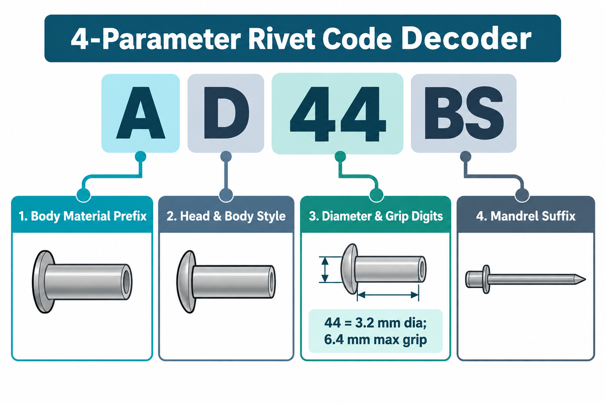
In the imperial POP rivet numbering system, a two-digit trade code such as 4-4 (or #44) defines the diameter of the rivet in increments of 1/32 inch (0.79 mm) with the first number, and the maximum grip thickness in increments of 1/16 inch (1.59 mm) with the second number. Alphanumeric part numbers such as AD44BS wrap that two-digit dash code between a two-letter body/head prefix and a two-to-three-letter mandrel suffix.
A frequent shop-floor mistake occurs when technicians trained on solid aircraft rivets (such as AN470 / MS20470) read blind rivet dash codes using solid-rivet rules. In solid aircraft rivets, a dash code like AD4-4 means 4/32 inch (1/8 inch) diameter by 4/16 inch (1/4 inch) total shank length. In blind rivets, 4-4 means 4/32 inch (1/8 inch / 3.2 mm) body diameter by 4/16 inch (1/4 inch / 6.4 mm) maximum grip range; the actual under-head body length of a 4-4 open-end pop rivet is approximately 0.375 to 0.400 inch (9.5 to 10.2 mm). Similarly, a trade size 45 rivet (written 4-5 or #45, as in AD45ABS) has a 4/32 inch (1/8 inch / 3.2 mm) diameter and a maximum grip of 5/16 inch (0.3125 inch / 7.9 mm).
To avoid ordering errors between imperial dash codes and metric ISO callouts, use the table below alongside Bolt Depot’s blind rivet sizing guide .
| Code Position | Symbol / Digits | Decoded Meaning | Example 1: AD44BS |
Example 2: AD45ABS |
Example 3: SSD68SS |
|---|---|---|---|---|---|
| 1. Body Material Prefix | A = Aluminum alloyS = Carbon steelSS = Stainless steelM = Monel (Ni-Cu)C = Copper |
Alloy of the tubular sleeve that remains in the joint | A = Aluminum 5052/5056 sleeve |
A = Aluminum sleeve |
SS = 300-series Stainless sleeve |
| 2. Head & Body Style | D = Open-end DomeK = Countersunk (120°)L = Large FlangeD...H = Closed-end |
Flange profile and open vs sealed end configuration | D = Standard Dome Head |
D = Standard Dome Head |
D = Standard Dome Head |
| 3. Diameter & Grip Digits | 1st digit = Dia in 1/32 in 2nd digit(s) = Max grip in 1/16 in |
Trade size dash code (3-2, 4-4, 4-5, 6-8) |
44 = 4/32 in (1/8 in / 3.2 mm) dia; 4/16 in (1/4 in / 6.4 mm) max grip |
45 (size 45 rivet) = 1/8 in dia; 5/16 in (7.9 mm) max grip |
68 = 6/32 in (3/16 in / 4.8 mm) dia; 8/16 in (1/2 in / 12.7 mm) max grip |
| 4. Mandrel Suffix | BS = Breakstem SteelABS = Aluminum BreakstemSS = Stainless Mandrel |
Material and break-mode of the pull mandrel | BS = Zinc-plated carbon steel mandrel |
ABS = Aluminum breakstem mandrel |
SS = Stainless steel mandrel |
In metric ISO drawings governed by ISO 15977:2002 for aluminum/steel open-end dome-head blind rivets (which superseded the withdrawn DIN 7337:1991-08 specification), part callouts bypass fractional dash codes and write nominal diameter by nominal body length directly in millimeters, such as 3.2 x 8 mm, 4 x 10 mm, or 4.8 x 12 mm. When converting between the two systems, remember that a metric callout prints body length (L = 8 mm), whereas an imperial dash code prints maximum grip (-4 = 6.4 mm grip).
POP Rivet Size Chart: Imperial and Metric Diameters with Drill Hole Sizes
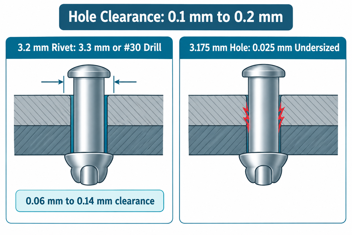
Matching each standard blind rivet diameter to its specified drill size requires adding 0.1 mm to 0.2 mm (0.004 to 0.008 inch) of clearance above the nominal sleeve diameter. Under ISO 15977:2002 Table 2, the five primary nominal diameters (2.4 mm, 3.2 mm, 4.0 mm, 4.8 mm, and 6.4 mm) require finished clearance hole diameters d1 of 2.5–2.6 mm, 3.3–3.4 mm, 4.1–4.2 mm, 4.9–5.0 mm, and 6.5–6.6 mm, while Allfasteners’ blind rivet size guide pairs trade codes #3 through #8 with 2.5 mm, 3.3 mm, 4.1 mm, 4.9 mm, and 6.5 mm metric drills (and US wire drills #30, #20, and #11 for #4, #5, and #6).
| Trade Code | Imperial Rivet Diameter | Nominal Metric Diameter | Recommended Hole Size Range (mm / in) | US Wire / Letter Drill Bit | Metric Drill Bit | Typical Dome Flange Dia (Df) |
|---|---|---|---|---|---|---|
| #2 | 1/16 in (0.063 in) | 1.6 mm | 1.65–1.75 mm (0.065–0.069 in) | #51 (0.0670 in / 1.70 mm) | 1.7 mm (0.0669 in) | 3.2 mm (0.125 in) |
| #3 | 3/32 in (0.094 in) | 2.4 mm | 2.46–2.56 mm (0.097–0.101 in) | #40 (0.0980 in) or #41 (0.0960 in) | 2.5 mm (0.0984 in) | 4.8 mm (0.188 in) |
| — (Metric) | 0.118 in | 3.0 mm | 3.10–3.20 mm (0.122–0.126 in) | #31 (0.1200 in) | 3.1 mm (0.1220 in) | 6.0 mm (0.236 in) |
| #4 | 1/8 in (0.125 in) | 3.2 mm | 3.26–3.34 mm (0.129–0.133 in) | #30 (0.1285 in / 3.26 mm) | 3.3 mm (0.1299 in) | 6.4 mm (0.250 in) |
| #5 | 5/32 in (0.156 in) | 4.0 mm | 4.08–4.20 mm (0.160–0.165 in) | #20 (0.1610 in / 4.09 mm) | 4.1 mm (0.1614 in) | 8.0 mm (0.312 in) |
| #6 | 3/16 in (0.188 in) | 4.8 mm (or 5.0 mm) | 4.86–5.00 mm (0.192–0.196 in) (5.1 mm for 5.0 mm ISO) |
#11 (0.1910 in) or #10 (0.1935 in) | 4.9 mm (or 5.1 mm) | 9.5 mm (0.375 in) |
| #7 | 7/32 in (0.219 in) | 5.6 mm | 5.68–5.80 mm (0.224–0.228 in) | #1 (0.2280 in / 5.79 mm) | 5.7 mm or 5.8 mm | 11.1 mm (0.438 in) |
| #8 | 1/4 in (0.250 in) | 6.4 mm (or 6.0 mm) | 6.48–6.62 mm (0.257–0.261 in) | Letter F (0.2570 in / 6.53 mm) | 6.5 mm (0.2559 in) | 12.7 mm (0.500 in) |
What Size Hole Should You Drill for a 3.2 mm POP Rivet?
For a 3.2 mm (1/8 inch, trade size #4) pop rivet, drill a 3.3 mm hole using a 3.3 mm metric twist drill bit or a #30 US wire gauge drill bit (0.1285 inch / 3.26 mm). This creates a finished rivet hole between 3.26 mm and 3.34 mm (0.129 to 0.133 inch), giving the 3.2 mm rivet shank 0.06 mm to 0.14 mm of insertion clearance.
Avoid drilling holes for metric 3.2 mm rivets with a standard fractional 1/8-inch (0.1250 inch) drill bit. Because 0.1250 inch equals exactly 3.175 mm, a fractional 1/8-inch hole is 0.025 mm smaller than a nominal 3.20 mm metric rivet body. As sheet-metal fabricators and aviation maintenance technicians frequently report, forcing a 3.2 mm rivet into a 3.175 mm hole scrapes the aluminum sleeve, pushes a burr between the mating sheets, or tempts operators to ream the hole by tilting the drill, which creates an oval bore that weakens shear capacity.
POP Rivet Grip Range Chart and Body Length Calculation Formula
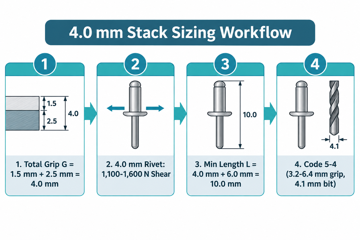
To choose the right blind rivet length, you first add the thicknesses of all the sheets, coatings, and gaskets to find the total grip thickness (G), and then pick a catalog dash code whose published grip range brackets G. When a manufacturer chart is unavailable for estimation, the minimum under-head body length is L ≥ Gmax + (1.2 to 1.5) × D for open-end rivets and L ≥ Gmax + 2.0 × D for closed-end sealed rivets.
As Huck Aerobolt’s blind rivet technical guide explains, the extra 1.2D to 1.5D (or to add 1.5 times the rivet diameter in preliminary layout) provides the length of the protruding tubular metal needed to fold into a blind-side locking bulb. According to sheet-metal industry standards, clients must choose the rivets whose published grip windows span the measured stack; closed-end sealed rivets need approximately 2.0D beyond the back sheet because the solid cup that seals the mandrel head can’t be compressed as tightly as an open tubular tail.
| Category / Type & Dash Code | Rivet Diameter (D) | Grip Range (Imperial in) | Grip Range (Metric mm) | Typical Open-End Body Length L & Application |
|---|---|---|---|---|
3-2 (#32) |
3/32 in (2.4 mm) | 0.031–0.125 in (1/32–1/8 in) | 0.8–3.2 mm | 5.7–6.2 mm (0.225–0.244 in) |
3-4 (#34) |
3/32 in (2.4 mm) | 0.126–0.250 in (1/8–1/4 in) | 3.2–6.4 mm | 8.9–9.5 mm (0.350–0.375 in) |
4-2 (#42) |
1/8 in (3.2 mm) | 0.063–0.125 in (1/16–1/8 in) | 1.6–3.2 mm | 6.4–7.0 mm (0.250–0.275 in) |
4-3 (#43) |
1/8 in (3.2 mm) | 0.126–0.187 in (1/8–3/16 in) | 3.2–4.8 mm | 8.0–8.6 mm (0.315–0.338 in) |
4-4 (#44) |
1/8 in (3.2 mm) | 0.188–0.250 in (3/16–1/4 in) | 4.8–6.4 mm | 9.5–10.2 mm (0.375–0.400 in) |
4-5 (#45) |
1/8 in (3.2 mm) | 0.251–0.312 in (1/4–5/16 in) | 6.4–7.9 mm | 11.1–11.5 mm (0.437–0.453 in) |
4-6 (#46) |
1/8 in (3.2 mm) | 0.313–0.375 in (5/16–3/8 in) | 7.9–9.5 mm | 12.7 mm (0.500 in) |
5-4 (#54) |
5/32 in (4.0 mm) | 0.126–0.250 in (1/8–1/4 in) | 3.2–6.4 mm | 10.3–11.0 mm (0.405–0.433 in) |
6-4 (#64) |
3/16 in (4.8 mm) | 0.126–0.250 in (1/8–1/4 in) | 3.2–6.4 mm | 10.8–11.5 mm (0.425–0.453 in) |
6-8 (#68) |
3/16 in (4.8 mm) | 0.376–0.500 in (3/8–1/2 in) | 9.5–12.7 mm | 17.2–18.0 mm (0.677–0.709 in) |
8-8 (#88) |
1/4 in (6.4 mm) | 0.376–0.500 in (3/8–1/2 in) | 9.5–12.7 mm | 19.0–20.0 mm (0.750–0.787 in) |
Worked Example: Sizing Diameter, Grip Code, and Body Length for a 4.0 mm Sheet Stack
Assumed inputs: Suppose an assembly engineer joins a 1.5 mm (0.059 in) powder-coated aluminum enclosure door to a 2.5 mm (0.098 in) galvanized steel hinge bracket, subject to a 1,200 N shear load across two rivets (600 N per rivet). Based on the grip chart and load table:
1. Total material grip thickness (G): G = 1.5 mm + 2.5 mm = 4.0 mm (0.157 in).
2. Diameter selection (D): Using the rule that rivet diameter should be at least 1.5 to 3 times the thinnest sheet (1.5 mm × 2.5 = 3.75 mm), compare trade size #4 (3.2 mm) and trade size #5 (4.0 mm). A single 3.2 mm aluminum/steel rivet (`AD-BS`) breaks at 760–1,100 N single shear, whereas a 4.0 mm `AD-BS` rivet breaks at 1,100–1,600 N, giving a 1.8× to 2.6× safety factor per fastener at 600 N.
3. Minimum body length calculation (Lmin): For an open-end 4.0 mm (#5) rivet, Lmin = G + 1.5D = 4.0 mm + (1.5 × 4.0 mm) = 10.0 mm. (For a 3.2 mm #4 rivet, Lmin = 4.0 mm + 4.8 mm = 8.8 mm.)
4. Dash code and drill selection: In the #5 (4.0 mm) series, dash code 5-3 (or 5-4, grip range 3.2–6.4 mm, body length 10.3 mm) places the 4.0 mm stack squarely inside the middle of the grip window, drilled with a 4.1 mm or #20 drill bit. In bulk procurement, standard aluminum/steel open-end rivets in these sizes are packaged in cartons of 500 to 10,000 pieces.
Can a POP Rivet Be Too Long or Too Short for the Material Thickness?
Yes; selecting a pop rivet whose grip range is either shorter or longer than the actual material thickness prevents a proper joint clamp. A rivet that’s too short can’t reach through the back sheet to form a locking bulb, and a rivet that’s too long upsets its bulb in mid-air before pulling the sheets tight.
When your measured sheet thickness falls directly on the boundary between two dash codes, such as a 3.2 mm (1/8 inch) stack sitting at the exact maximum grip limit of a 4-2 rivet (1.6–3.2 mm) and the minimum limit of a 4-3 rivet (3.2–4.8 mm), always step up to the longer grip code (4-3) or specify a multi-grip blind rivet. Paint build-up, sheet thickness tolerances, and slight inter-sheet gaps routinely add 0.15 mm to 0.30 mm, pushing a boundary joint past the maximum grip length of the shorter code.
Large Flange POP Rivet Sizes, Countersunk Heads and Body Styles

Standard blind pop rivets come in three head geometries-dome head (about 2.0D flange diameter), large flange (about 3.0D flange diameter) and 120-degree countersunk flush head- paired with five body structures: open-end, closed-end sealed, multi-grip, structural locked-mandrel, and peel/tri-fold sleeves.
According to Albany County Fasteners’ blind rivet reference, selecting the right type of rivet and head style is just as important as picking the shank diameter. Each rivet type distributes clamping force differently: when fastening thin aluminum, fiberglass, or composite panels where a sheet-metal screw would strip out, a standard dome head concentrates pull-up stress into a narrow annulus, whereas a countersink bit prepares flush seating for 120-degree heads. Upgrading to large flange pop rivet sizes creates a more durable joint by expanding head diameter from 6.4 mm (0.250 in) to 9.5 mm (0.375 in) on a #4 (3.2 mm) rivet, and from 9.5 mm (0.375 in) to 15.9 mm (0.625 in) on a #6 (4.8 mm) rivet.
Worked Example: Bearing Area Gain of Large Flange vs Dome Head (#4 / 3.2 mm Rivet)
Assumed inputs: Compare a standard dome head (Df = 6.4 mm) and a large-flange head (Df = 9.5 mm) installed in a 3.3 mm drilled hole (Dh = 3.3 mm) under an axial clamping tension of 800 N:
• Dome head net bearing area: Adome = (π / 4) × (6.42 − 3.32) = 0.7854 × (40.96 − 10.89) = 23.62 mm2 → Compressive stress = 800 N / 23.62 mm2 = 33.9 MPa.
• Large flange net bearing area: ALF = (π / 4) × (9.52 − 3.32) = 0.7854 × (90.25 − 10.89) = 62.33 mm2 → Compressive stress = 800 N / 62.33 mm2 = 12.8 MPa.
Switching to a large-flange head increases bearing area by 2.64× and cuts surface compressive stress by 62%, preventing pull-through on low-yield materials without adding a separate front-side washer.
| Head or Body Type | Key Geometric Feature | Primary Industrial Application | Engineering Limitation / Boundary |
|---|---|---|---|
| Dome Head (Open-End) | Flange diameter ≈ 2.0D; low-profile rounded cap | General metal-to-metal sheet fabrication, HVAC, enclosures | Not watertight; mandrel head is held only by friction |
| Large Flange Head | Flange diameter ≈ 3.0D (2.6× bearing area) | Joining thin gauge metal, plastics, composites, or oversized holes on top sheet | Only widens the factory head side; blind side still upsets a standard bulb unless paired with a backup washer |
| 120° Countersunk Head | Conical flush head (100° in aerospace); length L includes head height | Aerodynamic surfaces, sliding drawers, electronics chassis | Top sheet thickness must exceed countersunk head height (typically ≥1.0–1.5 mm for 3.2–4.0 mm rivets) to avoid knife-edge tearing |
| Closed-End (Sealed) Body | Cup-shaped sealed tail completely encloses the mandrel head | Watertight roofing, boat hulls, IP-rated electrical cabinets, EV battery trays | Requires longer body allowance (Gmax + 2.0D) and tighter grip tolerance than open-end rivets |
| Multi-Grip Body | Stepped or grooved sleeve forms controlled double bulbs (see patent US9593706B2) | Variable sheet stacks; replaces 2 to 3 fixed-grip SKU sizes | Lower ultimate shear capacity than mechanically locked structural blind rivets |
| Peel / Tri-Fold (Exploding) Body | Slotted sleeve splits into 3 or 4 wide petals on the blind side | Soft or brittle materials: ABS, PVC, rubber, plywood, drywall, fiberglass | Low shear/tensile strength; not suitable for structural metal-to-metal joints |
Can You Rivet Plastic and Brittle Sheet Materials Without Cracking Them?
Yes, plastic, fiberglass and brittle composite panels can be riveted by pairing an all-aluminum low-pull-force blind rivet with a large-flange head, a tri-fold or peel-type expanding body, or a stainless backup burr washer on the blind side. Standard steel-mandrel open-end rivets put excessive radial expansion pressure on thermoplastics, which causes them to split around the hole.
When fastening a soft or brittle sheet on the blind side (where the upset bulb forms), even a large-flange head on the front side will not stop the tail from digging into the back of the plastic. Either add a flat metallic backup washer over the protruding sleeve on the blind side before pulling the mandrel, or use a tri-fold or peel rivet whose slotted shank folds outward into three or four wide petals that spread clamping force over a wide area.
POP Rivet Shear Strength Chart and Tensile Loads by Size and Alloy
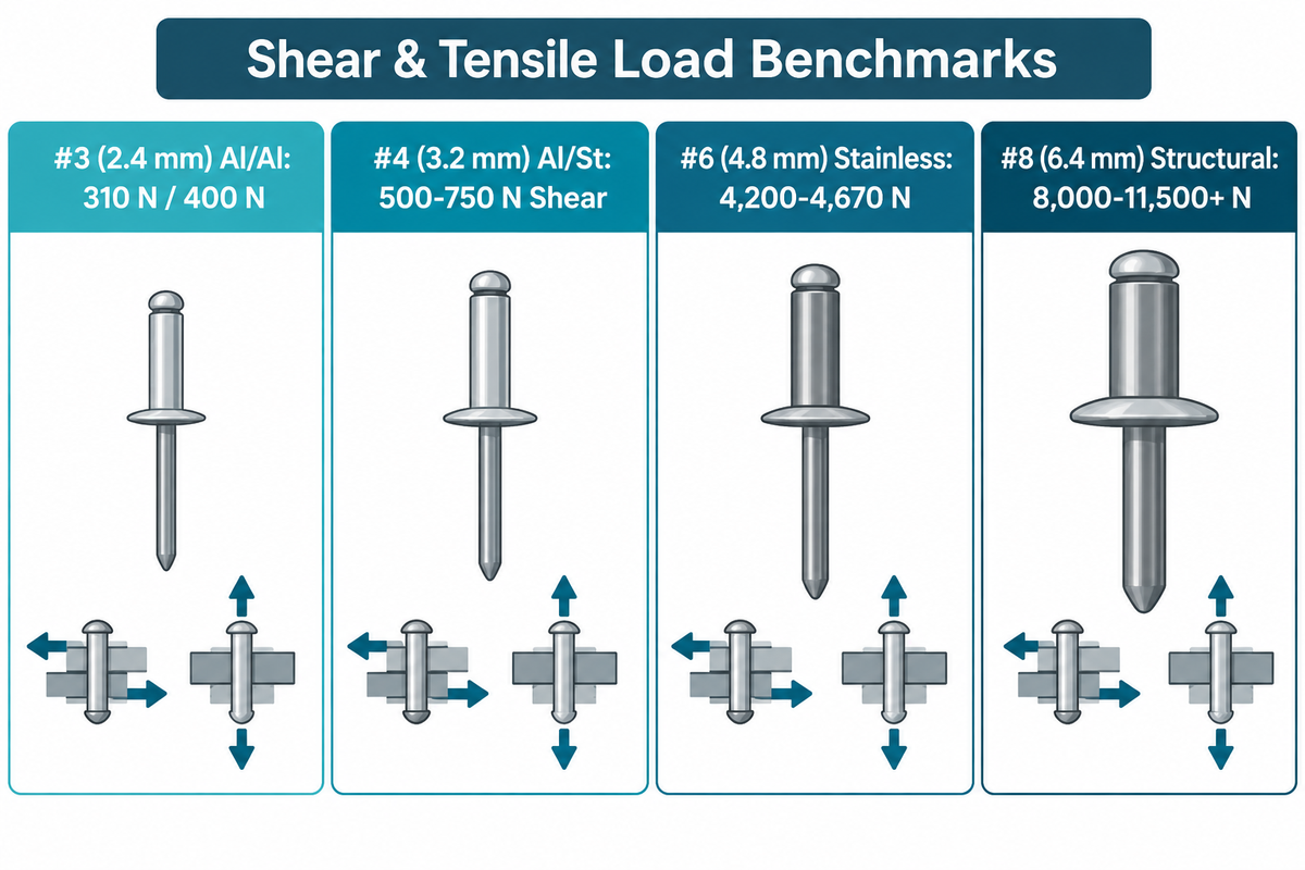
Single-shear and tensile breaking strength for blind pop rivets increases with the square of the body diameter and the shear modulus of the sleeve alloy. Under ISO 15977:2002 Table 3, a 3.2 mm (#4) aluminum/steel open-end blind rivet is rated for a minimum single-shear load of 500 N (low grade) to 750 N (high grade) and a minimum tensile load of 600 N to 1,100 N, whereas a 6.4 mm (#8) high-grade aluminum/steel rivet is rated for a minimum single-shear load of 2,500 N and a minimum tensile load of 3,500 N (with supplier catalog values for steel and structural locked-mandrel series reaching 4,900 to over 11,000 N).
In standard open-end breakstem rivets, joint strength is governed by the tubular rivet body after the mandrel breaks away; undersized holes hinder insertion, while oversized holes reduce both shear and tensile strength and cause sheet separation.
As discussed in CNC Lathing’s blind pop rivet strength chart and methods and joint design of sheet metal fastening, engineers must also account for galvanic corrosion when pairing rivet alloys with base sheets. Carbon steel rivets are unsuitable for marine aluminum panels, and copper rivets are unsuitable for aluminum or galvanized steel assemblies, as electrolyte exposure rapidly corrodes the more anodic metal. Aluminum 5052/5056 rivets pair safely with aluminum sheets, while 304/316 stainless steel or Monel (nickel-copper alloy) rivets are specified for corrosive chemical and marine environments.
| Rivet Diameter (Trade / mm) | All-Aluminum (AD-ABS)Shear / Tensile |
Aluminum Body / Steel Mandrel (AD-BS, ISO 15977)Shear / Tensile |
Steel Body / Steel Mandrel (SD-BS, ISO 15979)Shear / Tensile |
Stainless Steel (SSD-SS, ISO 15983)Shear / Tensile |
Structural Locked-Mandrel (Steel/Al) Shear / Tensile |
|---|---|---|---|---|---|
| #3 — 3/32 in (2.4 mm) | 310 N (70 lbf) / 400 N (90 lbf) |
530–620 N (120–140 lbf) / 690–780 N (155–175 lbf) |
580–760 N (130–170 lbf) / 760–980 N (170–220 lbf) |
1,000–1,150 N (225–260 lbf) / 1,250–1,420 N (280–320 lbf) |
Not applicable (stocked ≥4.8 mm) |
| #4 — 1/8 in (3.2 mm) | 530 N (120 lbf) / 670 N (150 lbf) |
500–750 N ISO min (760–1,100 N catalog) / 600–1,100 N ISO min (1,000–1,350 N catalog) |
1,150–1,470 N (260–330 lbf) / 1,380–1,780 N (310–400 lbf) |
1,870–2,100 N (420–470 lbf) / 2,200–2,500 N (495–560 lbf) |
Not applicable (stocked ≥4.8 mm) |
| #5 — 5/32 in (4.0 mm) | 850 N (190 lbf) / 1,020 N (230 lbf) |
1,100–1,600 N (245–360 lbf) / 1,500–2,100 N (335–470 lbf) |
1,690–2,230 N (380–500 lbf) / 2,090–2,750 N (470–620 lbf) |
2,890–3,200 N (650–720 lbf) / 3,500–3,850 N (785–865 lbf) |
Not applicable (stocked ≥4.8 mm) |
| #6 — 3/16 in (4.8 mm) | 1,160 N (260 lbf) / 1,420 N (320 lbf) |
1,700–2,400 N (380–540 lbf) / 2,200–3,100 N (495–700 lbf) |
2,600–3,600 N (585–810 lbf) / 3,100–4,400 N (700–990 lbf) |
4,200–4,670 N (945–1,050 lbf) / 5,000–5,560 N (1,125–1,250 lbf) |
4,000–6,200 N (900–1,395 lbf) / 3,500–4,900 N (785–1,100 lbf) |
| #8 — 1/4 in (6.4 mm) | 2,050 N (460 lbf) / 2,490 N (560 lbf) |
3,100–4,200 N (700–945 lbf) / 4,000–5,300 N (900–1,190 lbf) |
4,900–6,400 N (1,100–1,440 lbf) / 5,800–7,500 N (1,305–1,685 lbf) |
7,500–8,450 N (1,685–1,900 lbf) / 8,900–10,000 N (2,000–2,250 lbf) |
8,000–11,500+ N (1,800–2,585+ lbf) / 6,800–9,500+ N (1,530–2,135+ lbf) |
Which Rivet Is Used for Heavy Structural Work and High-Vibration Joints?
Hot-driven or cold-squeezed solid steel rivets (with pan or button heads) and swaged lockbolts are used for two-sided heavy structural steel construction, bridges, and aircraft frames. When access to only one side of a load-bearing joint is available, mechanically locked mandrel structural blind rivets (such as Monobolt, Magna-Lok or Interlock) in 4.8 mm (3/16 in) and 6.4 mm (1/4 in) diameters are specified.
Unlike hardware-store open-end pop rivets, where the mandrel snaps at a narrow neck and leaves a hollow sleeve in the shear plane, a structural blind rivet expands to fill the hole completely and mechanically swages a locking ring or internal lock-groove around the hardened steel stem inside the shear plane. Retaining a mechanically locked solid steel stem across the joint interface can increase the single-shear breaking load and prevent loss of the stem in service.
What Happens When a POP Rivet Hole Is Too Big? Tolerance, Edge Distance and Defect Triage
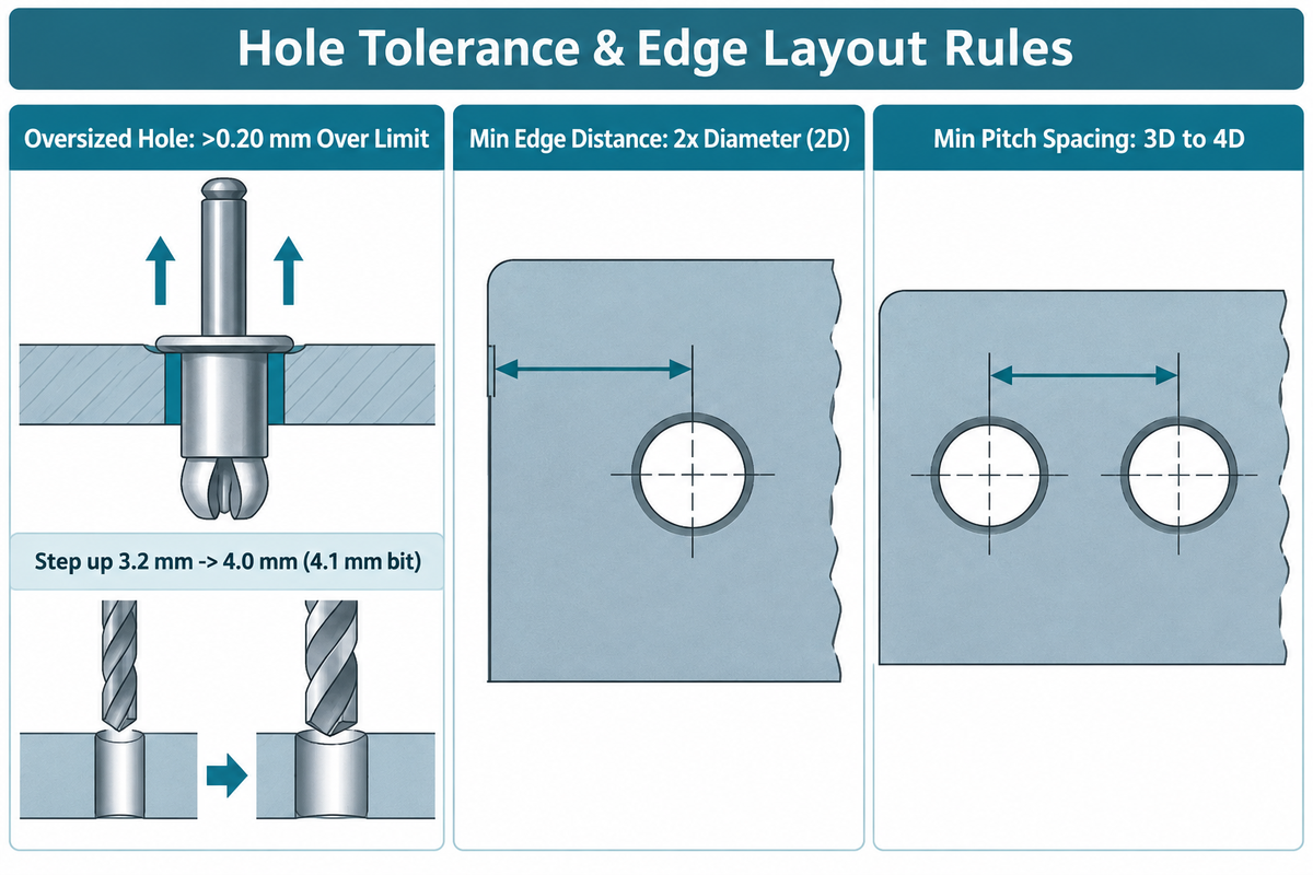
When a pop rivet hole is drilled more than 0.2 mm (0.008 inch) above the recommended clearance range, the tubular sleeve cannot expand far enough radially to grip the bore walls, causing the mandrel head to pull straight through the sleeve, the blind bulb to buckle off-center, or the installed rivet to spin loose under load.
Observance of edge and spacing rules is also critical for proper joint layout. In accordance with FAA sheet-metal fastening standards and Assembly Magazine’s blind riveting engineering handbook, hole centerlines must sit at least 2× the rivet diameter (2D) away from any free sheet edge to prevent edge tear-out, and adjacent rivets must be spaced at a minimum pitch of 3D to 4D so setting tool noses clear adjacent heads without buckling the sheet. Comparing self-piercing riveting joint quality and defect diagnosis against pre-drilled blind riveting highlights how sensitive breakstem fasteners are to hole preparation:
| Observed Joint Defect | Dimensional / Mechanical Root Cause | Corrective Engineering Action |
|---|---|---|
| Mandrel pulls through sleeve or forms weak bulb | Hole drilled >0.20 mm over max tolerance (e.g., >3.5 mm for a 3.2 mm rivet) | Add a close-fitting backup burr washer on the blind side, use a multi-grip expanding rivet, or re-drill to the next trade diameter (step up #4 3.2 mm → #5 4.0 mm with a 4.1 mm drill) |
| Rivet sleeve refuses to insert or peels on entry | Hole drilled net-size (e.g., 1/8 in / 3.175 mm bit used for a 3.20 mm ISO rivet) or heavy exit burr | Switch to the specified wire/metric drill (#30 / 3.3 mm for #4 rivets) and deburr both hole faces lightly |
| Sheets remain gapped / loose after mandrel snaps | Rivet grip range is too long (bulb upsets before reaching back sheet) or inter-sheet drilling chips trapped | Step down to the dash code matching actual stack thickness G; clamp sheets tightly before drilling and setting |
| Mandrel breaks flush or protrudes above factory head | Rivet grip range is too short for total material thickness (excessive stack thickness) | Measure total thickness including paint/gaskets and select the next longer dash code |
| Rivet spins in the hole during service or removal | Elongated/oval hole from off-axis hand drilling or insufficient radial shank expansion | Use drill bushings on thin panels; upgrade to hole-filling structural or multi-grip blind rivets |
| Sheet edge bulges or tears out under shear load | Hole centerline placed closer than 2× rivet diameter (2D) from sheet edge | Maintain ≥2D edge distance (e.g., ≥6.4 mm for a 3.2 mm rivet; ≥9.6 mm for a 4.8 mm rivet) |
Pop Rivets vs Self-Piercing Rivets (SPR), Clinching and Orbital Riveting in Production

For small to medium batches, blind pop riveting can be efficient. However, high volume sheet-metal fabrication processes outgrow this technology because every joint requires pre-drilling, deburring, and alignment of holes. When two-sided C-frame access exists, automated self-piercing riveting (SPR), clinching, or orbital riveting cuts cycle time from 8–15 seconds to 1.5–3.0 seconds per point.
As detailed in Assembly Magazine’s production riveting analysis, in automotive body-in-white, EV battery enclosures, appliance cabinets, and elevator panels, using pre-drilled holes leads to cumulative tolerance stack-up and contamination of the work area with metal swarf. Switching to servo self-piercing rivet automation systems eliminates the need for hole drilling. Upgrading to servo self-piercing rivet automation systems eliminates hole drilling altogether: a semi-tubular hardened rivet, driven at 30 to 80 kN by a servo or hydro-pneumatic C-frame press, pierces the top sheet and flares into a lower die button to create a gas-tight, high-fatigue mechanical interlock without breaking through the bottom sheet.
Worked Example: Takt-Time Comparison Across a 40-Point Sheet Metal Enclosure
Assumed inputs: Suppose an industrial cabinet or battery tray assembly requires 40 fastening points joining 1.5 mm and 2.0 mm aluminum sheets, with C-frame access along the perimeter flanges:
• Manual pre-drilled blind pop riveting: Drilling, deburring, aligning holes, inserting #6 (4.8 mm) blind rivets, pulling stems, and emptying the mandrel collector averages 10 seconds per point → 40 × 10 s = 400 seconds (6.67 minutes) per assembly, plus 40 spent steel mandrels as scrap.
• Automated SIMITCH Servo SPR or Clinching cell: With zero pre-drilled holes and automatic tape/blow feeding at 2.0 seconds per point → 40 × 2.0 s = 80 seconds (1.33 minutes) per assembly.
Direct joining cycle time is reduced by 80% (saving 5.33 minutes per unit) by eliminating hole preparation and manual stem pulling, while providing real-time force-displacement curve verification on every joint.
Use the 3-Gate Blind-to-Automated Riveting Selector below to evaluate whether an assembly should remain on blind pop rivets or move to automated press-joining equipment:
| Engineering Criterion | Blind POP Riveting (Manual / Autofeed Gun) | Self-Piercing Riveting (SPR, Servo / Hydro-Pneumatic) | Mechanical Clinching (Fastener-Free Press) | Servo Orbital / Radial Riveting |
|---|---|---|---|---|
| Gate 1: Joint Access Required | One-sided (blind) — only front access needed; requires tail clearance behind sheet | Two-sided C-frame — punch above, lower anvil die beneath bottom sheet | Two-sided C-frame — punch and die cold-form parent sheets together | Two-sided fixture — anvil supports solid/semi-tubular pin during orbital head forming |
| Gate 2: Hole Preparation & Consumable | Requires pre-drilled/punched hole (+0.1–0.2 mm tolerance); leaves snapped mandrel waste | Zero pre-drilling; semi-tubular rivet pierces top sheet and flares into bottom sheet (zero scrap) | Zero pre-drilling & zero consumable fastener; draws parent metal into an interlock button | Uses pre-formed hole or integral boss with solid or semi-tubular rivet pin (zero mandrel scrap) |
| Gate 3: Cycle Time & Force Window | 8–15 s/point (manual drill + pull); 2–4 s/point (autofeed gun into pre-punched holes); 3–18 kN pull force | 1.5–3.0 s/point; 30–80 kN C-frame pressing force | 1.2–2.5 s/point; 25–60 kN C-frame pressing force | 1.5–3.5 s/point; low axial force (2–25 kN) via 3°–6° orbital peening tool |
| Dynamic Fatigue & Sealing | Moderate (open-end); requires closed-end or structural rivets for sealing/vibration | High dynamic fatigue life; bottom sheet remains unbroken and inherently watertight | Good static/fatigue strength on ductile 0.5–4.0 mm sheets; unbroken bottom layer | High concentricity and controlled clamp load; ideal for hinges, rotors, and precision pins |
| Best-Fit Production Scenario | Closed box sections, field MRO, low-volume mixed enclosures | High-volume aluminum/steel automotive BIW, EV battery trays, HVAC & appliance frames | High-volume coated steel/aluminum ductwork, appliances, elevator & electrical panels | Automotive latches, seat mechanisms, hardware pivots, and thick-pin assemblies |
When considering industrial riveting machine manufacturers, Suzhou Simitch Machinery Co., Ltd. (SIMITCH) engineers and manufactures automated riveting equipment and assembly systems, including servo self-piercing riveting (SPR) C-frame systems, pneumohydraulic clinching machines, and servo press workstations, for sheet metal and precision assembly lines. If your production team is assessing whether to automate a riveted assembly, copy the specification checklist below and send it along with your part drawings to the SIMITCH engineering team to evaluate your request.
RFQ checklist — copy these into your quote request:
| Parameter | Recommended Specification Entry | Why It Matters | How to Verify |
|---|---|---|---|
| Sheet Stack & Alloys | Exact thickness and grade of each layer (e.g., 1.5 mm Al 5052 + 2.0 mm galvanized steel, total grip 3.5 mm) | Determines blind rivet grip code or SPR/clinching punch-and-die geometry | Caliper check on coated production coupons |
| Joint Access & Throat Depth | One-sided blind only vs two-sided C-frame reach (specify max throat depth in mm) | Decides between blind riveting and hole-free SPR/clinching | 3D CAD fixture and C-frame interference check |
| Target Load & Sealing | Required single-shear/tensile load (N) and IP/watertight rating | Selects open-end vs closed-end vs structural locked-mandrel or SPR | Destructive coupon pull test per ISO 15977 / ISO 14273 |
| Takt Time & Quality Traceability | Points per assembly, annual volume, and force-displacement monitoring requirements | Sizes manual/autofeed tools vs servo press automation | Timed trial run and SPC curve export check |
Frequently Asked Questions About POP Rivets Sizes
How do I know what size pop rivet to use?
Measure two independent dimensions: First, pick a rivet body diameter at least three times the thickness of the thickest sheet being joined, or match the existing hole diameter minus 0.1 to 0.2 mm; second, measure the total thickness of all sheets and pick a dash code whose grip range spans that total thickness.
What is the grip range of a 3.2 x 12 mm rivet?
A standard open-end 3.2 x 12 mm (1/8 inch diameter by 12 mm body length, dash code 4-6) blind rivet typically covers a material grip range of 6.5 mm to 8.5 mm (approximately 0.256 to 0.335 inches). Always verify the exact minimum and maximum grip values on the manufacturer’s ISO 15977 specification table.
Are pop rivets sizes measured in inches or millimeters?
POP rivets are manufactured and specified in both imperial (inch) and metric (millimeter) systems. North American distributor catalogs follow fractional inch sizes (such as 1/8 inch and 3/16 inch with dash-number codes), while ISO 15977:2002 (which superseded the withdrawn DIN 7337:1991-08 standard) specifies nominal metric diameters (including 2.4 mm, 3.2 mm, 4.0 mm, 4.8 mm, and 6.4 mm) by body length.
What is the smallest standard pop rivet size?
The smallest stocked industrial blind pop rivet is trade size #3, measuring 3/32 inch (2.4 mm) in diameter and requiring a #40 or 2.5 mm drill.
When should you choose a rivet nut or bolt instead of a blind pop rivet?
Choose a blind rivet nut (threaded insert) or a structural bolt and nut whenever the assembly must be disassembled for periodic maintenance, field service, or component replacement, or when clamping loads exceed the tensile capacity of a breakstem mandrel. A breakstem mandrel cannot hold the assembly when the tensile loads exceed its limiting capacity. Blind pop rivets are permanent, non-removable fasteners designed primarily for shear loads in thin sheets of metal; M4 to M10 rivet nuts provide reusable internal machine threads in sheets too thin to tap directly.
Do stainless steel pop rivets use the same hole size as aluminum rivets?
Yes. Under ISO 15977 and ISO 15983, stainless steel and aluminum blind rivets of equal diameter use the exact same drill bit and hole tolerance.
Why do some blind rivets leave the mandrel head rattling inside the joint?
Standard open-end breakstem rivets retain the snapped mandrel head solely by friction inside the upset tail. Standard open-end breakstem rivets retain the snapped mandrel head solely by friction inside the upset tail; if the hole is slightly oversized, the grip is near the minimum limit, or the assembly experiences heavy vibration, the mandrel head can work loose and rattle. Closed-end sealed rivets (which encapsulate the mandrel head in a cup) or a structurally locked blind rivet eliminate loose mandrel heads in automotive doors, appliances and other electrical enclosures.
References & Sources
- International Organization for Standardization (ISO), ICS 21.060.40: Rivets (ISO 15977, ISO 15979, ISO 15983 Blind Rivet Standards)
- STANLEY Engineered Fastening, POP Rivet Selection Factors: Hole Size, Grip Range, and Joint Strength
- Bolt Depot, Fastener Information: Blind Rivet Sizing and Dash Numbers
- All fasteners, Blind Rivet Size Guide: Diameter, Grip Range, and Drill Bit Chart
- CNC Lathing, Blind Pop Rivet Size Chart, Drill Hole Sizes, and Shear/Tensile Strength Dimensions
- Albany County Fasteners, Fasteners 101: Blind Rivets Head Styles, Large Flange Dimensions, and Material Selection
- Huck Aerobolt – Complete Guide to Blind Rivets and Structural Breakstem Fasteners
- Assembly Magazine, Assembly Handbook: Blind Riveting Principles and Process Control
- Assembly Magazine, Riveting the Blind Side: Structural and Automated Fastening
- Federal Aviation Administration (FAA), Advisory Circular Technical Standards for Fastener Edge Distance and Pitch
- Google Patents, US9593706B2: Multi-Grip Blind Rivet and Mechanical Locking Assembly
Reviewed by the SIMITCH technical team. Dimensional and mechanical load ranges are compiled from published ISO 15977–15983, IFI-114, and manufacturer catalog tables; always verify critical structural joints against the specific fastener lot datasheet and physical coupon pull tests.






WHY WE WRITE THIS
About SIMITCH
SIMITCH develops sheet-metal joining equipment for clinching, riveting, servo pressing, pneumohydraulic drive and hot-melt connection applications. Our engineering team starts with the material stack, access envelope, cycle target and acceptance method before recommending a machine route.
Founded in 2006 in Taicang, Jiangsu, SIMITCH combines research and development, in-house production and global sales. These guides turn field experience into practical decision support for process engineers, plant teams and industrial buyers.
OUR EXPERIENCE
Since 2006
Equipment engineering, machining, assembly and joint validation under one manufacturing system.
OUR EXPERTISE
Five joining routes
Clinching, riveting, SPR, precision press-fit and hot-melt connection for production lines.