Get in touch with Suzhou Simitch Machinery Co., Ltd Company

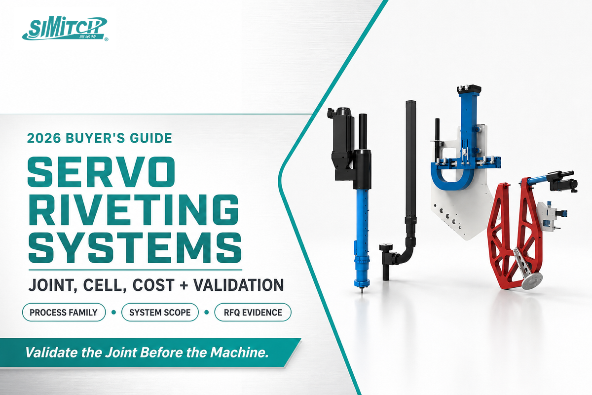
Servo riveting assembly systems are automated joining machines that connect sheet-metal stacks by driving a rivet through the top layer, then flaring it into the bottom layer under closed-loop servo-motor control, with no pre-drilling or added heat. The process is increasingly used on automotive body, EV battery-enclosure, and appliance production lines that join aluminum, coated steel, and dissimilar-metal sheet stacks — applications where resistance spot welding can be difficult.
In production environments, advanced servo riveting technology combines precision riveting control with real-time cycle data, helping manufacturers maintain consistent quality while improving production efficiency compared with manual riveting.
In essence, a servo riveting assembly system combines a servo-driven power unit, a matching rivet-and-tooling assembly, automated feeding, and sensors to form self-piercing rivets with controlled force and position. One equipment manufacturer reports an upfront premium of roughly 25-40% over comparable pneumatic equipment; in continuous, high-duty-cycle production, the servo system avoids the pneumatic machine’s compressed-air demand.
Key Points
- Servo is the drive architecture, not the joining-process name; confirm whether a quote covers SPR, orbital forming, impact riveting, or a servo press before comparing specifications.
- Academic strength comparisons are mixed: some tests report SPR joints at 1.2 to 1.5 times the strength of resistance spot welds, while others report 25-30% lower strength, depending on material and test mode.
- Self-piercing riveting applications usually require setting forces roughly ten times those used for resistance spot welding.
- While process-monitoring data can flag anomalies, it doesn’t substitute for physical joint verification with mechanical tests.
- For smaller manufacturers, capital approval can delay automation even when the engineering case is sound; use the Cost section to compare machine price with integration, energy, maintenance, and downtime.
Quick Specs
| Typical setting force range (market) | 20-80 kN, application-dependent |
| Position accuracy (published reference model) | 0.01 mm repeat positioning, SIMITCH model-specific |
| Cell architectures | Stationary C-frame, robot-mounted, floor-standing deep-throat |
| Servo cost premium vs. pneumatic | Reported 25-40% higher initial cost (single vendor source, confirm with your own quotes) |
| SIMITCH published reference model | 80 kN / 200 mm stroke / 0-333 mm/s / +/-2% pressure accuracy / 0.01 mm repeat positioning |
For an exact configurable spec table and RFQ, see SIMITCH’s servo riveting assembly system configurator.
What Is a Servo Riveting Assembly System?
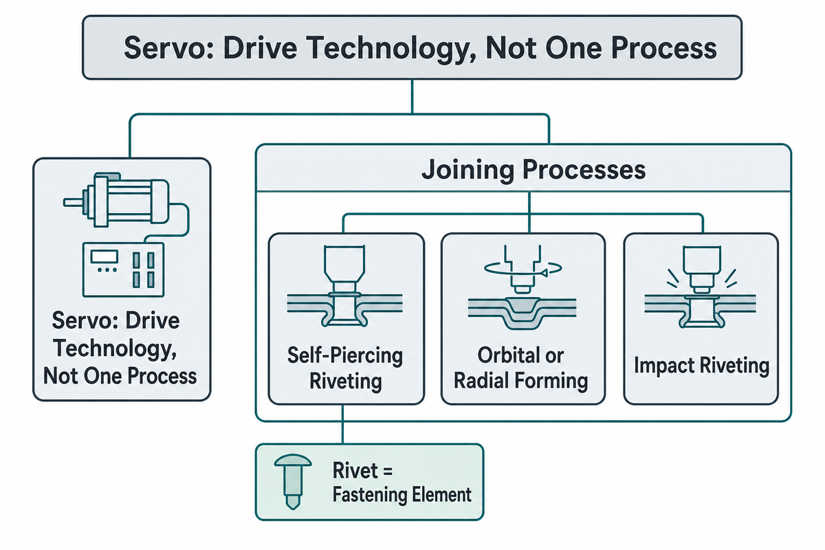
Servo riveting is a drive-technology category, not one process — a servo motor supplies the closed-loop force and position control behind several joining processes, including self-piercing riveting, orbital or radial forming, and impact riveting. This guide, and SIMITCH’s own system, use the term specifically for self-piercing riveting (SPR): a rivet pierces the top sheet, doesn’t pass through the bottom sheet, and flares to form a mechanical interlock without heat or a pre-drilled hole.
During the assembly process, the rivet is the fastening element; the cell can assemble the joint without drilling that hole first.
An orbital riveting head — the wobbling forming tool at the center of that process — is a completely different mechanism from an SPR punch-and-die set, even when both get marketed under a “servo riveting” label. Several equipment makers use “servo riveting” for orbital or roller-forming machines with no piercing action at all, so the mechanical interlock described above is what distinguishes SIMITCH’s specific usage of the term from that broader industry naming confusion.
This distinction matters when evaluating vendors: a quote labeled “servo riveting machine” may describe a roller or impact forming tool with no piercing action, while another supplier may use the same label for an SPR solution. Confirm the joining process each product actually performs before comparing options.
Key industrial application areas for self-piercing riveting include automotive body manufacturing, EV battery enclosures, home and commercial appliance assembly, and lift-and-transit construction.
How Self-Piercing Riveting Compares to Other Joining Methods
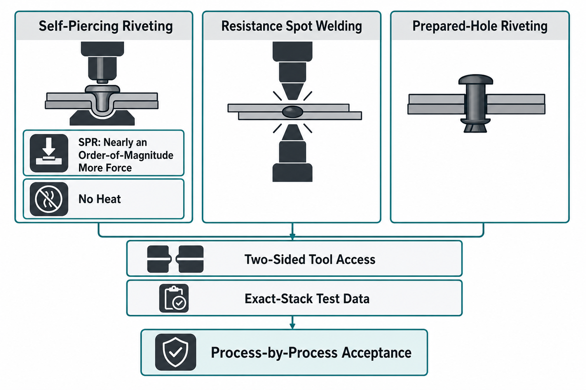
Self-piercing riveting systems require forces nearly an order of magnitude greater than spot-weld equipment — a ratio from the well-known SAE-published SPR engineering research (TWI/Henrob/ABB) that holds roughly steady even though the absolute force varies by application. That force requirement helps explain why an SPR station generally needs a heavier load path and frame than a spot-weld gun.
| Method | Heat / Fastener | Dissimilar Materials | Limitations / Not suitable for |
|---|---|---|---|
| Self-piercing riveting (SPR) | No heat, uses a rivet | Yes, including coated/painted stacks | Needs two-sided tool access; conventional low-ductility magnesium lower sheets are prone to cracking |
| Resistance spot welding | Heat, no fastener | Limited; struggles with dissimilar/coated stacks | Not for aluminum-to-steel without special electrodes; heat-affected zone risk |
| Orbital/radial riveting | No heat, uses a rivet (often pre-drilled) | Yes | Usually needs a pre-formed hole; different tooling and acceptance review than SPR |
| Structural adhesive bonding | No heat, no mechanical fastener | Yes | Cure time; surface-prep sensitive; usually paired with a mechanical joint, not used alone in high-load areas |
The strength comparison doesn’t always come out in favor of SPR. Some studies report SPR joint strength at 1.2 to 1.5 times that of resistance spot welds in tension-shear and cross-tension tests. Other studies report SPR joints at 25-30% lower strength under different steel and aluminum combinations and test modes. Don’t accept a vendor claim that SPR simply “is stronger” without test data for your exact material stack. These riveting techniques also require different tooling: an orbital riveting machine, or hydraulic or pneumatic equipment used to form solid rivets in prepared holes, does not use the same pierced-and-flared interlock as SPR. Strength and acceptance criteria must therefore be compared process by process.
Servo, Pneumatic, or Hydraulic: Choosing the Right Drive Technology
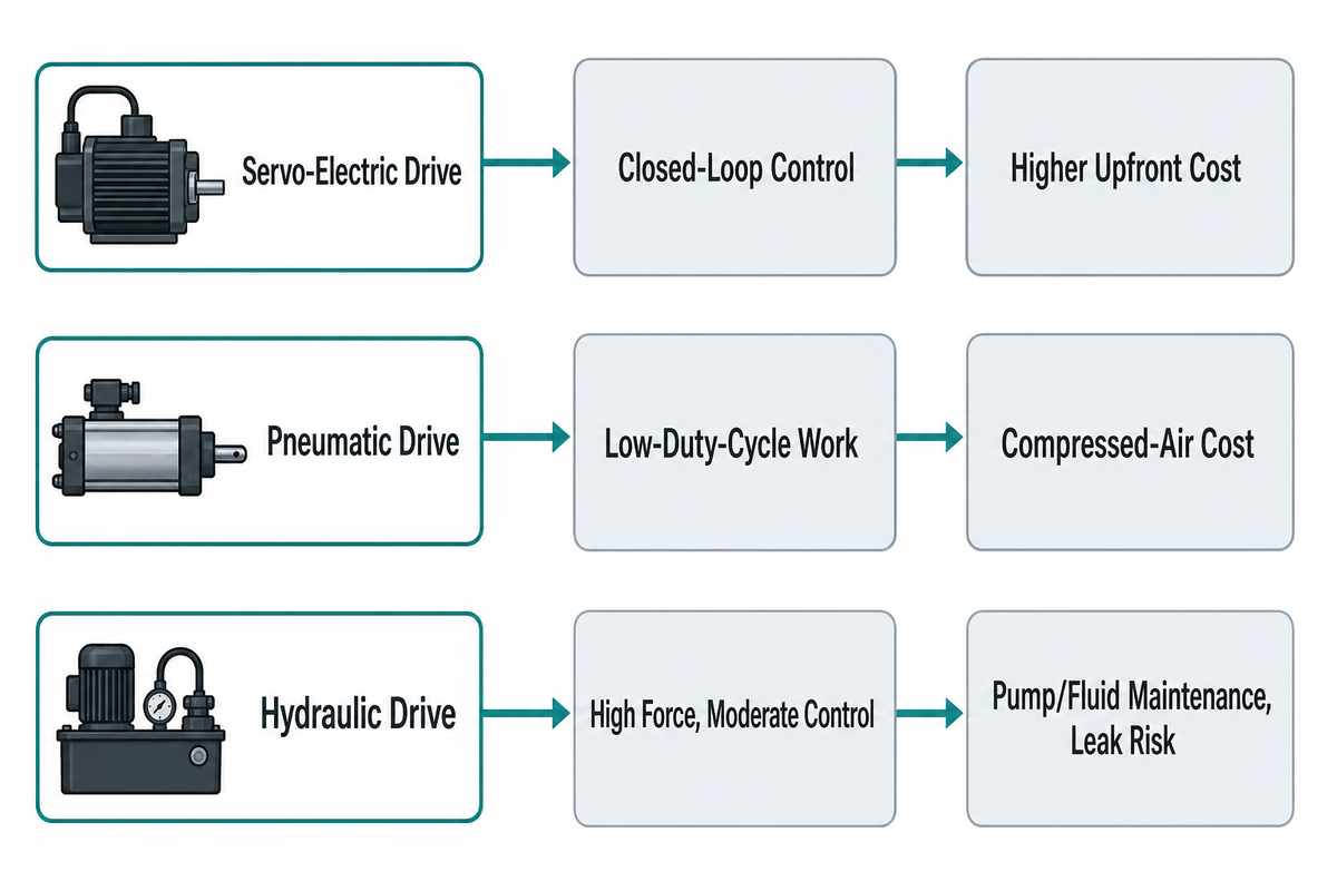
Servo-electric drives give closed-loop control over force, position, and speed throughout the riveting stroke, which pneumatic and hydraulic systems can’t match with the same resolution — but that precision advantage doesn’t automatically translate into a lower operating cost in every application. Under continuous, high-duty-cycle production, compressed air’s system efficiency of only 10-15% (and compressed-air generation commonly running about 10% of a plant’s total electricity use, sometimes 30% or more) becomes a real, ongoing cost that a servo system eliminates. Under long-idle or low-duty-cycle operation, that gap narrows substantially — a 2002 Tokyo Institute of Technology study in the Proceedings of the JFPS International Symposium on Fluid Power found it’s a misunderstanding to call pneumatic cylinders unconditionally less efficient than electric actuators, since pneumatic cylinders draw little power while stopped and become the more efficient option once stop time is relatively long.
| Drive Type | Force/Position Control | Operating Cost Driver | Limitations / Not suitable for |
|---|---|---|---|
| Servo-electric | Closed-loop, programmable per cycle | No compressed air; higher electronics/training cost | Higher upfront cost; more operator training on controls |
| Pneumatic | Fixed or limited-step force | Compressed-air generation, ~10-15% typical system efficiency | Air-quality/moisture maintenance; less precise on tight tolerance stacks |
| Hydraulic | High force, moderate control resolution | Pump/fluid maintenance, leak risk | Fluid contamination risk near sensitive assemblies (e.g. electronics) |
One equipment maker’s published guidance states servo-driven riveting machines can cost 25-40% more upfront than a comparable pneumatic riveting machine, depending on machine options and utility requirements — that figure comes from a single vendor source, not an independent industry average, so confirm it against your own quotes.
Servo Riveting vs. Servo Press: Don’t Confuse These Two Technologies
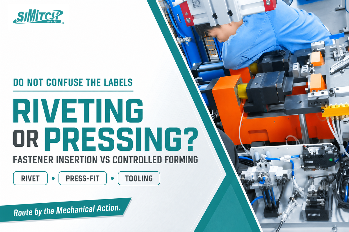
A servo riveting assembly system sets a rivet — the mechanical fastener — through the material stack. A servo press system applies controlled pressing force without inserting a fastener, often to press-fit bearings, bushings, or other components, or to perform a forming or staking operation. Both use servo-motor control for precision, and both may come from the same manufacturer, which is why the names get confused. If your joint needs a rivet, you want a riveting system; if your operation is a controlled press-fit or forming step with no rivet involved, see SIMITCH servo press systems for controlled pressing instead.
Inside a Servo Riveting Assembly System
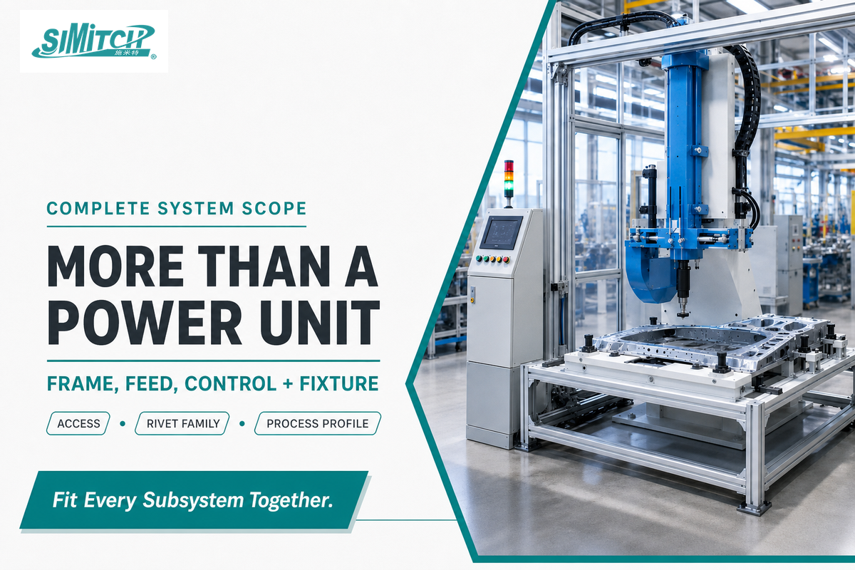
A complete servo riveting assembly system combines five subsystems: a servo-driven power unit for controlled force and motion; an application-specific gun and C-frame that position the tooling at the joint; a rivet feeder and magazine; presence and process-detection sensors; and a control system that coordinates them. Buying a high-force power unit alone doesn’t solve a joining problem — the frame geometry, feed path, and fixture access must fit the actual part. The controller coordinates force, speed, and position across multiple axes. Its adjustable force control system stores critical parameters in validated profiles for multiple rivets within one compatible family, while the insertion machine’s feed hardware still has to be configured for the selected size.
Cell architecture comes in three configurations. A stationary C-frame suits parts that can be reliably presented to a fixed gun, minimizing moving mass. A robot-mounted lightweight frame suits distributed joint locations across a larger part, at the cost of managing payload, cable routing, and collision envelope. A floor-standing deep-throat frame reaches farther into large fixtures without adding robot payload, at the cost of foundation and service-access planning. For its published configurations, SIMITCH lists 100-600mm throat reach for stationary frames, 600-900mm for robot-mounted frames, and up to 1500mm for floor-standing frames. As one published reference model, SIMITCH’s own servo riveting assembly system is specified at 80 kN maximum force, 200 mm stroke, 0-333 mm/s programmable speed, +/-2% pressure accuracy, and 0.01 mm repeat positioning accuracy, figures the manufacturer publishes for that specific model, not a category-wide standard.
SIMITCH also lists a 2-row magazine with 35 rivets per row (70 total); 3mm and 5mm rivets must not be mixed in one feed setup.
Material and Rivet-Stack Compatibility
Self-piercing riveting (SPR) can join several material combinations, including aluminum-to-steel and pre-painted or coated sheet. Stack-up flexibility is not unlimited; a rivet-and-die combination validated for one set of material grades and thicknesses may not work for another. Edge distance also affects joint strength: controlled studies have reported an approximately 30% drop when the distance was reduced below a well-supported condition. Rivet hardness creates another process boundary: a rivet that is too soft may not pierce and flare correctly, while one that is too hard may punch through.
Two more constraints can rule out an otherwise desirable stack. SPR needs two-sided tool access, so fully enclosed single-access joint locations are not candidates. Conventional magnesium alloys have lower formability than steel or aluminum, making the lower sheet more likely to crack instead of flare. The tooling design and fastener specifications must therefore match the material stack and joint geometry.
The 6-Point Servo Riveting Fit Score
Servo Riveting Assembly System Selection by Scenario
Application geometry, material combination, surface condition, and production duty determine which joining process is viable. The matrix below routes nine representative scenarios; it does not replace validation on the actual part.
| Category | Scenario | Access | Recommended | Why |
|---|---|---|---|---|
| Automotive | Aluminum-to-steel body panel | Two-sided | Servo SPR | Dissimilar materials, no heat-affected zone |
| Automotive | High-strength steel structural member | Two-sided | SPR or spot welding — test both | Published strength comparisons are mixed by material/test mode |
| EV battery | Battery enclosure near heat-sensitive cells | Two-sided | Servo SPR | No heat input near sensitive components |
| Appliance | Painted or coated sheet-metal panel | Two-sided | Servo SPR | Spot welding damages the finish |
| Aerospace / rail | Long runs of repetitive panel or enclosure joints | Application-specific | Automated riveting after joint validation | Repeatability and traceability can justify automation, but process choice remains joint-specific |
| Materials | Low-ductility magnesium lower sheet | N/A | Not SPR — consider orbital riveting or adhesive bonding | Lower sheet is prone to cracking instead of flaring |
| Geometry | Enclosed cavity, single-side access only | Single-sided | Not SPR — blind rivet or adhesive | SPR physically needs two-sided tool access |
| Production | Frequent 3 mm / 5 mm rivet changeover at one station | N/A | Redesign station or add a second feed line | Mixing rivet sizes in one magazine is a feed-hardware failure point for the published SIMITCH setup |
| Volume | Low-volume or prototype run (well under 1,000 units/year) | N/A | Manual or pneumatic riveting | Servo automation usually needs enough volume or traceability value to justify the premium |
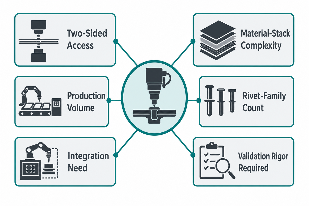
The 6-Point Servo Riveting Fit Score
Before asking suppliers for quotes, sort your application into the six categories below — doing so will help you and the vendors narrow down the applicable solutions, though this tool isn’t intended to replace the vendor’s own evaluation.
The 6-Point Servo Riveting Fit Score is a SIMITCH editorial decision aid, not an industry standard or an independently validated scoring system. Adapt it to your own engineering review and procurement rules.
Score each dimension 0-2 (0=poor fit, 1=workable, 2=strong fit), then sum:
- Two-sided access — Can you reach both sides of every joint location? (0 = no access at all; 2 = full access)
- Material-stack complexity — Aluminum/steel/coated combinations, excluding low-ductility magnesium (0 = magnesium or single-side-only stack; 2 = standard aluminum/steel/coated combination)
- Production volume — Does cycle-time and repeatability actually matter at your volume? (0 = very low volume, manual is fine; 2 = high-volume line)
- Rivet-family count — How many distinct rivet sizes/types will run through one station? (0 = frequent mixed sizes in one magazine; 2 = one rivet family per station)
- Integration need — Robot cell, PLC interface, or standalone station? (0 = complex multi-system integration with no in-house controls experience; 2 = simple standalone or well-scoped integration)
- Validation rigor required — Does the application need documented sample-trial and acceptance-criteria records? (0 = limited formal traceability; 2 = full traceability required, so servo data logging has decision value)
9-12: strong candidate for a servo riveting system. 5-8: workable, but confirm the access and material-stack items with a vendor before committing. 0-4: reconsider — a pneumatic system, orbital riveting, or adhesive bonding may fit better.
How to Evaluate and RFQ a Servo Riveting Vendor
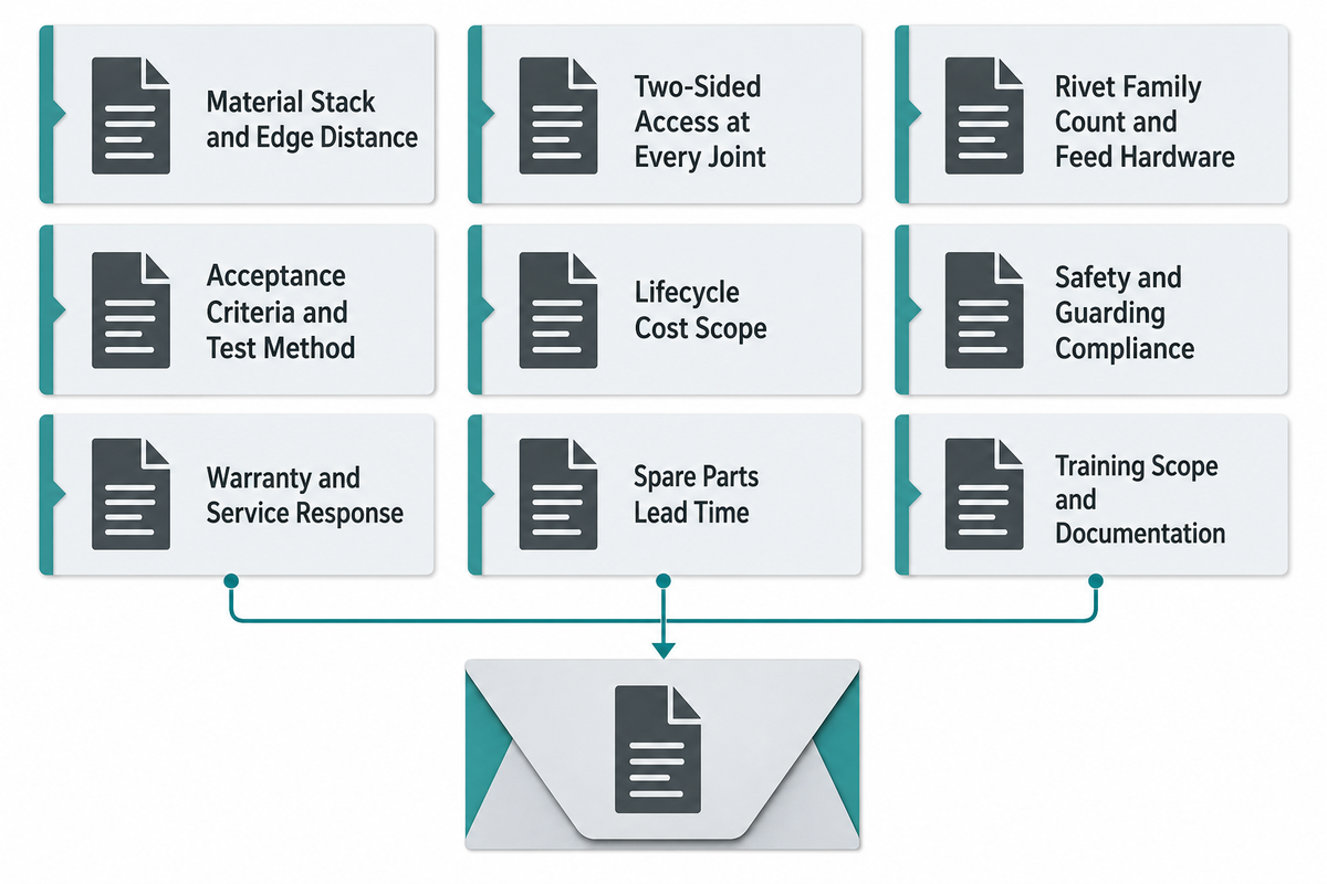
A credible RFQ separates verified equipment-envelope data from project-specific inputs that only your engineering team can supply — and no fixed checklist should be treated as complete. The U.S. National Institute of Standards and Technology’s Manufacturing Extension Partnership supplier-selection guidance explicitly frames its own guidance as a starting point, noting that additional questions will be specific to your circumstances rather than a restrictive, one-size-fits-all form.
RFQ checklist — copy these into your quote request:
| Parameter | Recommended range | Why it matters | How to verify |
|---|---|---|---|
| Material stack & edge distance | Confirm at every joint location, not just the “typical” one | 30% strength loss possible at tight edge distances | Request sample-trial cross-sections at your actual edge distances |
| Two-sided access at every joint | Confirm with the actual fixture/robot layout, not a CAD approximation | SPR is infeasible without both-side access | Physical mockup or robot reach study before final quote |
| Rivet family count & feed hardware | One rivet family per feed setup where possible | Mixed rivet sizes in one magazine is a known failure point | Ask the vendor to confirm feed-hardware compatibility in writing |
| Acceptance criteria & test method | Shear, peel, and cross-section geometry across an agreed sample set before tooling freeze | Process monitoring alone is not proof of joint acceptance | Request the vendor’s sample-trial report format up front |
| Lifecycle cost scope | Ask what is excluded from the quoted machine price | Tooling, integration, trials, and service are often billed separately | Request a scope-aligned commercial comparison, not just a headline price |
| Safety & guarding compliance | Point-of-operation guarding designed for the applicable requirements, including 29 CFR 1910.212 in the United States | Incomplete guarding can prevent acceptance until the design is corrected | Request the guarding risk assessment and applicable compliance documentation |
| Warranty & service response time | Define the response time your production risk requires, separately from warranty duration | Warranty length alone does not show how quickly production support will arrive | Request the service-level agreement in writing, not a verbal estimate |
| Spare parts lead time | Supplier-quoted lead time for dies, feed tubing, sensors, and other wear or critical parts | A long lead time can turn a minor part failure into extended downtime | Ask for a recommended spare-parts stocking list with item-specific lead times |
| Training scope & documentation | Hours of on-site training and whether manuals match your control software version | Under-trained operators lose much of the precision advantage you paid for | Request the training curriculum and documentation set before signing |
OSHA 29 CFR 1910.212 regulates guarding for covered workplace machinery rather than the purchasing transaction itself, but it should shape the RFQ. Ask how the bidder’s design supports point-of-operation guarding, secure anchoring, and compliant installation before final acceptance testing.
What Does a Servo Riveting Assembly System Cost?
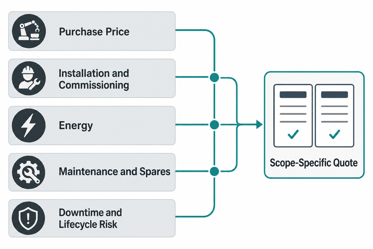
The total cost of ownership for a servo riveting assembly system includes five categories: purchase price, installation and commissioning, energy, maintenance, and downtime. No single public number describes the total cost, so treat any headline figure as an engineering starting point for a scope-specific quote. The U.S. Department of Energy compressed-air guidance supplies the energy-efficiency baseline used in the operating-cost comparison below.
Neither SIMITCH’s own product page nor the equipment manufacturer sources identified for this article publish a single servo-system capital expenditure number; force class, frame type, feed complexity, and integration scope for your application determine the actual budget. Reputable machine manufacturers position a servo system as a high-performance, comparatively low-maintenance alternative to pneumatic equipment, but whether it is cost-effective still depends on production volume and quality-control requirements.
Five-year cost categories to budget for (not a fixed-price table — build your own from vendor quotes):
| Cost item | What drives it |
|---|---|
| Purchase price | Force class, frame type, feed complexity; servo reported 25-40% above pneumatic per one vendor’s published range (confirm with your own quotes) |
| Installation & commissioning | Robot/fixture integration scope, PLC interface work, safety guarding to 29 CFR 1910.212 |
| Energy (5-yr) | Pneumatic: compressed-air generation, U.S. DOE estimates typical plant-wide system efficiency of only 10-15%. Servo: electricity only, no compressed-air overhead |
| Maintenance & spares (5-yr) | Wear parts, rivet/die replacement, scheduled service intervals (see Maintenance section below) |
| Downtime & lifecycle risk (5-yr) | For dissimilar-material joints: galvanic corrosion, coating/sealant compatibility, and end-of-life disassembly for metal-stream recycling add cost categories a same-material joint does not have |
Payback example (compressed-air side only, from one published worked example): the source machine is a bench-top orbital riveter — a different process family from the SPR systems this guide otherwise covers — and is used only to illustrate servo-versus-pneumatic air-cost arithmetic, not SPR-specific consumption. The example machine draws 0.120233 cubic feet of compressed air per cycle. At 1,080,000 parts per year, that equals about 129,852 cubic feet annually; at the source’s assumed $0.015 per cubic foot, the compressed-air line is about $1,947.77 per year. A comparable servo-electric process would avoid that compressed-air expense, but it would still consume electricity. The vendor’s per-cubic-foot rate is a planning estimate, not a universal benchmark. Use the formula (annual volume × air consumption per cycle × local air cost) with your own SPR machine and utility figures.
Cost can keep a plant on manual or pneumatic riveting even when automation is technically feasible. The “should I automate” capital-budget question is real, not hypothetical — which is why the five-category overview is more useful than a single headline number.
Validating Joint Quality: Beyond Force Curves
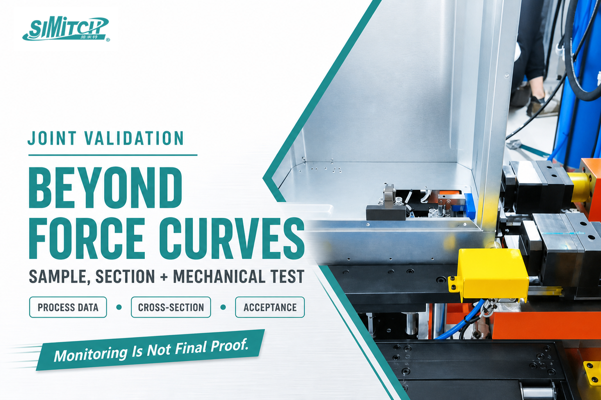
Higher setting force doesn’t win the joint. A peer-reviewed review of self-piercing riveting research published in the International Journal of Advanced Manufacturing Technology (2017) found the relationship between process parameters — including setting force and velocity — and final joint quality to be real but non-trivial, not a simple “more force, stronger joint” curve. Process monitoring — force, displacement, and time responses during the riveting cycle — can identify deviation, but it does not prove that the joint meets mechanical requirements. A well-cited SAE-published development paper on SPR equipment states that while its process monitor was able to detect changes in rivet length and die shape, “significant additional work would be required to establish the extent to which such a monitor would be able to detect variable quality factors such as variation in rivet/button profile and mechanical properties of the joint.” Even the equipment developers did not claim that monitoring replaces physical joint testing.
“Often, riveting of simple parts like a cigarette lighter can be fully automated. More-specialized assemblies like seating mechanisms and latching mechanisms for doors are more challenging for fully automated riveting.”
A real validation workflow runs sample trials before the tooling is frozen: review the parts (material grades, thicknesses, coatings, and stack order), define the system (rivet/die family, gun, frame, and station architecture), run sample trials with the proposed stack, agree on acceptance criteria, and only then release production tooling. Acceptance indicators commonly include rivet head height, interlock or flare geometry at a cut cross-section, remaining bottom-sheet thickness, and — for load-bearing joints — shear, peel, or fatigue test results. Adjust a nominal geometry limit only when test evidence demonstrates that the revised window still meets the agreed acceptance criteria; process-monitoring curves alone are not enough.
When NOT to Use Self-Piercing Riveting
SPR isn’t the right process for every stack. Skip it, or plan for a different process, when the joint location only has single-side access (SPR physically needs both sides), the lower sheet is a low-ductility magnesium alloy prone to cracking instead of flaring, or the visible backside button geometry is unacceptable for a cosmetic or sealed surface.
Skip it too when the stack order or rivet family would need to change mid-production without the required feed or tooling change. Mixing rivet sizes can create a feed-hardware failure point; SIMITCH’s published two-row feed setup, for example, does not permit 3 mm and 5 mm rivets in one setup. None of these constraints rule out servo riveting as a drive technology; they rule out self-piercing riveting for that specific joint and point toward orbital riveting, adhesive bonding, or a different joint design.
Industries and Applications
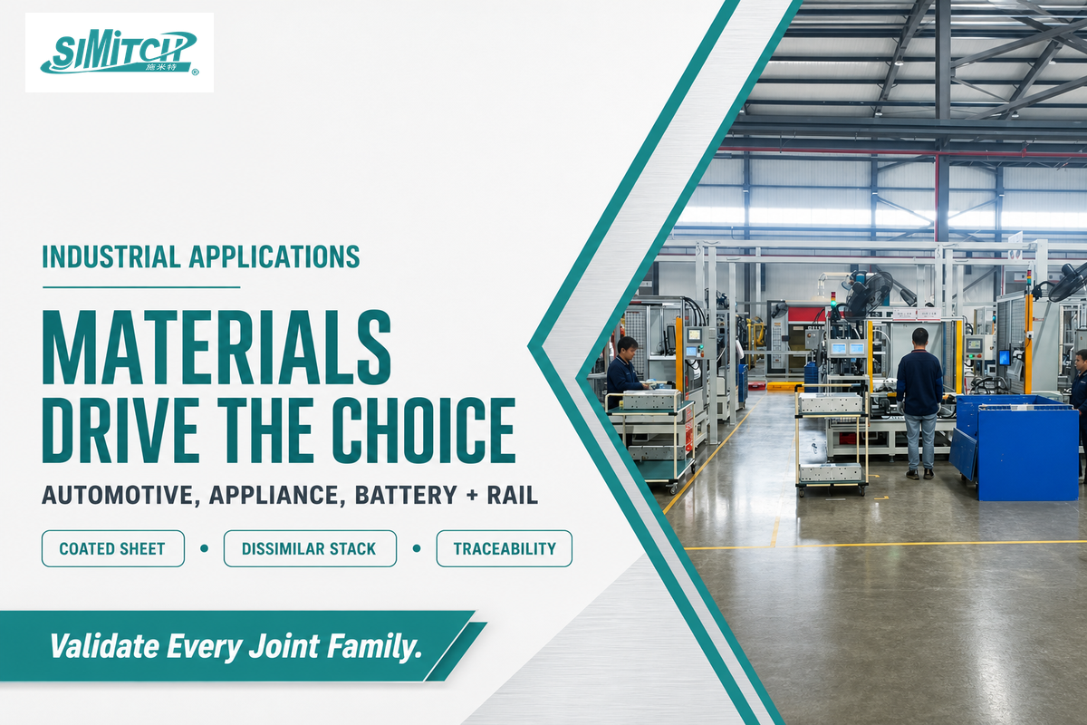
Self-piercing riveting is used wherever a production line needs to join dissimilar or coated materials without the heat input of welding. In automotive body assembly, it joins aluminum and high-strength steel components as manufacturers pursue vehicle lightweighting through multi-material joints — a combination resistance spot welding handles poorly. In EV battery-pack and electronics assembly, it fastens enclosures and structural components where heat input near sensitive cells or components is a real risk. In home appliance manufacturing, it joins painted or coated sheet-metal panels where spot welding would damage the finish, and parts often arrive from an upstream press brake or stamping line before reaching the riveting cell. In elevator and rail-transit fabrication, it supports automated riveting with process monitoring and data retention for traceability — see riveting equipment for elevator and rail-transit assembly for that application in more depth. More broadly across manufacturing, self-piercing and other automated riveting methods have long been used in aerospace body-panel assembly for similar reasons — joining lightweight, dissimilar, or coated materials without a heat-affected zone — though that’s an industry-wide pattern across the aerospace sector, not a claim about any specific manufacturer’s current customer base or about primary structural joints like wing-skin-to-stringer attachment, which more commonly use solid or blind rivets for fatigue-critical, single-side-access assembly.
Maintenance, Service Life, and Uptime Planning
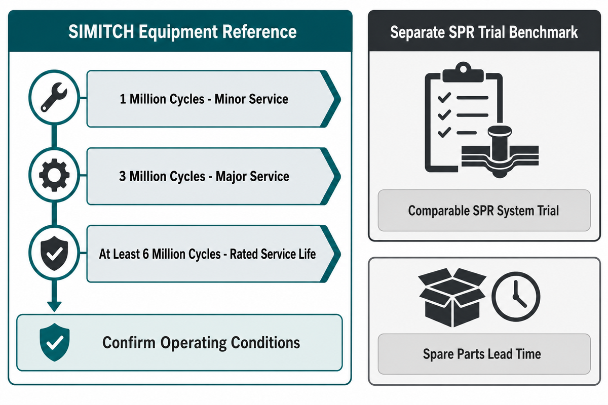
Plan servo riveting maintenance around scheduled cycle counts, not calendar time. As one published reference point, SIMITCH specifies minor service at 1 million cycles and major service at 3 million cycles, with a rated service-life reference of at least 6 million cycles — figures the manufacturer publishes for its own equipment, not a guarantee that transfers to every operating condition. In the same SAE 2001-01-0979 factory trials of a comparable SPR system cited above (TWI/Henrob/ABB), a prototype unit achieved 96% technical availability (4% downtime) and 99.96% technical efficiency (0.04% failure-stop rate) across 86,000 rivets set, which gives a useful real-world benchmark for what “well-maintained” looks like in practice, separate from any single vendor’s rated figures. Maintenance requirements and long-run reliability matter as much as day-one price; tracking quality issues over the machine’s service life is part of the total cost of ownership, not a separate line item. For a related maintenance example, see SIMITCH’s evidence-based portable clinching maintenance guide.
Industry Outlook
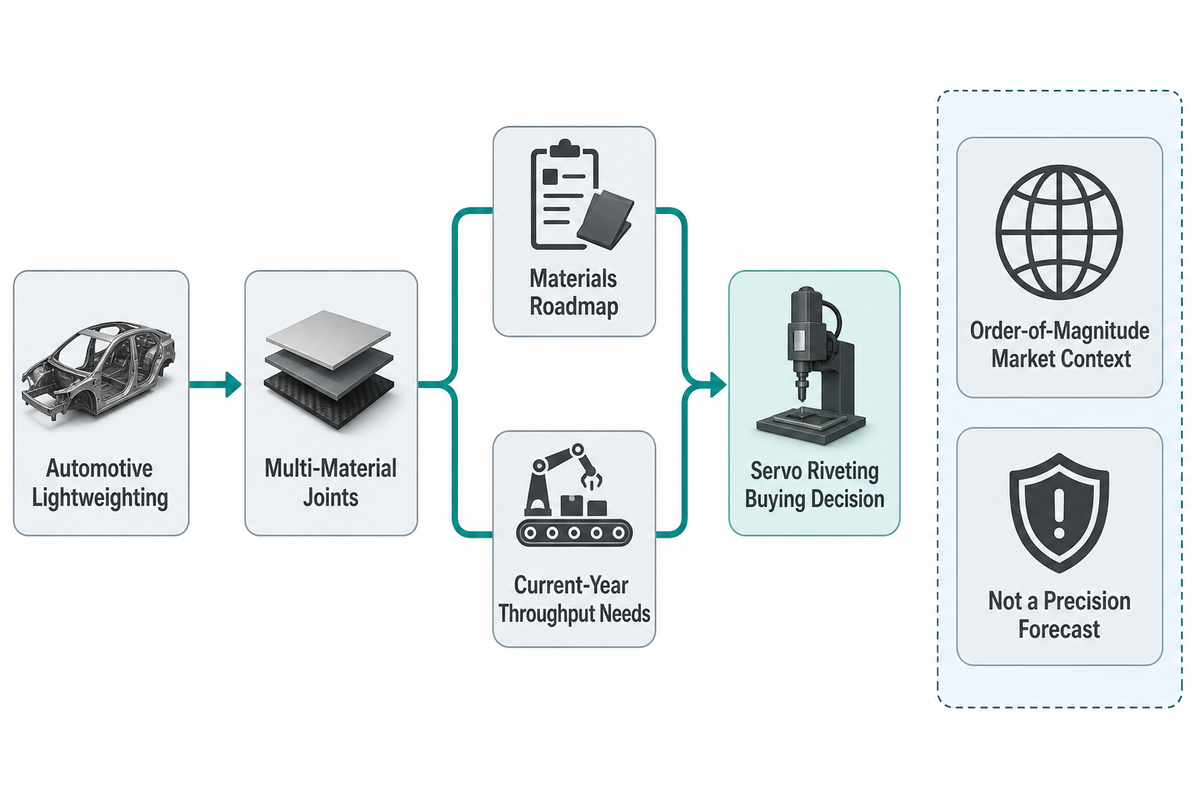
The real driver behind growing servo riveting adoption isn’t “automation is growing” in the abstract — it’s that automotive lightweighting keeps pushing manufacturers toward multi-material joints that resistance spot welding can’t join reliably, and self-piercing riveting is one of the few processes that can. That’s a materials-driven shift, not a generic productivity story, and it means the buying decision for a servo riveting system should be evaluated against your own materials roadmap, not just current-year throughput needs. Market-size figures support this directionally without being the main point: industry estimates put the broader automatic riveting machine and equipment market at roughly USD 268.8 million in 2025, growing toward USD 409.5 million by 2035 (a 4.3% compound annual rate), with the aerospace riveting-equipment segment specifically projected to grow faster, around 6.8% annually through the early 2030s. A number of servo riveting assembly systems manufacturers now compete in that space, alongside longer-established pneumatic and orbital equipment builders. Treat these figures as order-of-magnitude market context, not a precision forecast for your own purchasing timeline.
FAQ: Servo Riveting Assembly Systems
Q: What’s the difference between self-piercing riveting and orbital riveting?
Self-piercing riveting pierces and flares a rivet into an un-drilled stack in one stroke; orbital riveting forms the head of a rivet that is usually placed through a pre-drilled or pre-formed hole using an orbiting (wobbling) forming motion.
Both processes can be servo-driven, which is why the equipment gets confused. Self-piercing riveting is a single-step pierce-and-flare operation with no pre-drilled hole and works well for high-volume automated lines. Orbital riveting generally forms a rivet already seated through a hole, applying force progressively around the rivet head rather than all at once — useful where a lower peak force or a specific head profile is needed. The two use different tooling and different acceptance criteria, so treat them as separate process families when comparing vendor quotes, not as interchangeable “servo riveting” options.
Q: Can servo riveting join aluminum to steel or other dissimilar-metal stacks?
Yes, self-piercing riveting is commonly used for aluminum-to-steel and other dissimilar or coated stacks, within die- and rivet-geometry-dependent limits, but it is not universal, and low-ductility magnesium is a known exception.
SPR’s ability to join dissimilar materials without heat input is one of its main advantages over resistance spot welding, and it is a major reason automotive manufacturers use it for aluminum-to-steel body assemblies. The specific rivet and die geometry must match the exact stack; a combination validated for one aluminum-to-steel thickness pairing is not automatically correct for another. Conventional SPR can also be infeasible on low-ductility magnesium alloys because the lower sheet tends to crack rather than flare. Always request a sample-trial validation on your specific stack rather than assuming a general “dissimilar-material capable” claim covers your combination. Corrosion at the joint interface is a related consideration when the two metals in contact are galvanically dissimilar; ask the vendor how their rivet coating and any sealant approach addresses that risk for your specific alloy pairing, since a joint that meets mechanical strength targets on day one can still corrode faster than a same-material joint over years of field service.
Q: How much does a servo riveting assembly system typically cost?
No fixed public price exists for servo riveting systems; budget across five categories, purchase price, installation, energy, maintenance, and downtime risk, and request a scope-aligned quote rather than comparing a single headline number.
One equipment supplier reports a servo cost premium of roughly 25% to 40% over comparable pneumatic equipment; treat that as single-source guidance and verify it against your own quotes. A larger budgeting error is to compare machine price alone: tooling, integration, sample trials, and commissioning are often bid separately, so a low equipment price can expand quickly. Pneumatic equipment also carries compressed-air overhead that servo eliminates under continuous, high-duty-cycle operation, although the gap narrows with long idle periods. U.S. Department of Energy guidance places overall compressed-air system efficiency at only 10-15%, with many systems consuming about 10% of a plant’s electricity.
Q: Is self-piercing riveting stronger than spot welding?
Sometimes, but not always — the published research is genuinely mixed, showing SPR joints both stronger and weaker than spot welds depending on material and test method, so treat “SPR is stronger” as an oversimplification rather than a fact.
Some studies report SPR joints 1.2 to 1.5 times stronger than resistance spot welds under tension-shear and cross-tension testing. Other studies report SPR joints up to 25-30% weaker than spot welds in steel and aluminum specimens, depending on material combination and test mode. The honest summary is that relative strength depends heavily on the specific materials, thicknesses, and test method — not a fixed process-level ranking. If joint strength is safety-critical for your application, request comparative test data on your exact material stack rather than relying on a general claim from either process’s advocates.
Q: How long does it take to integrate a servo riveting cell into an existing assembly line?
Integration time is project-specific and depends on whether the cell is stationary, robot-mounted, or floor-standing and on the fixture, PLC, and guarding scope; there is no single published industry-standard duration.
Fixture readiness, robot programming, PLC integration, and safety-guarding work to 29 CFR 1910.212 are the main drivers. Ask any vendor to name every factor that could stretch the schedule, not just one headline number.
Q: What training or operator skill is needed to run a servo riveting cell?
Servo systems usually require more controls training than a fixed-action pneumatic setup because operators and maintenance staff must understand programmable force, speed, position, recipes, and alarms.
Because servo systems allow programmable force, speed, and position profiles rather than a fixed action, operators and maintenance staff need training specifically on those controls, not just on general machine operation. Build this into your procurement timeline and budget as a line item, not an afterthought — a system that’s under-utilized because operators only use its default settings loses much of the precision advantage you paid for. Vendors can often customize the training scope to your team’s existing controls experience, so ask what’s included before you sign. Training your workforce on fixturing and controls, not just the riveting head itself, is what actually adapts a system to your specific manufacturing needs.
Why We Write This
The guide compiles published equipment engineering literature, U.S. and international government sources, and SIMITCH’s own published product data to give servo riveting assembly system buyers an independently sourced starting point — separate from any single vendor’s marketing claims. Where the underlying research disagreed (strength comparisons, energy-efficiency claims, cost premiums), we reported the disagreement rather than picking the more favorable number. Reviewed by the Suzhou Simitch Machinery Co., Ltd. technical team.
References & Sources
- The Development of Lightweight Self-Piercing Riveting Equipment (SAE 2001-01-0979) TWI Ltd / Henrob Ltd / ABB Body-in-White / Technical University of Dresden
- An Overview of Self-piercing Riveting Process with Focus on Joint Failures, Corrosion Issues and Optimisation Techniques Chinese Journal of Mechanical Engineering (Springer)
- Self-piercing riveting — a review — Li, Chrysanthou, Patel & Williams (2017), The International Journal of Advanced Manufacturing Technology, Warwick WMG
- Energy Comparison of Electric and Pneumatic Actuators — Kagawa (2002), Proceedings of the JFPS International Symposium on Fluid Power, Tokyo Institute of Technology
- Non-destructive monitoring of forming quality of self-piercing riveted joints Scientific Reports (Nature)
- 29 CFR 1910.212, General requirements for all machines U.S. Occupational Safety and Health Administration
- Manufacturer’s Pre-Purchase Guide to Equipment NIST Manufacturing Extension Partnership
- 8 Ways to Improve Your Supplier Selection Process NIST Manufacturing Extension Partnership
- Compressed Air Tip Sheet #1 U.S. Department of Energy
- Creating a strong and reliable joint with self-piercing rivets Atlas Copco Industrial Technique
- Automating the Riveting Process ASSEMBLY Magazine
- Automatic Riveting Equipment Market Future Market Insights (market-research estimate, directional context only)
- Aerospace Riveting Equipment Market Strategic Market Research (market-research estimate, directional context only)