Get in touch with Suzhou Simitch Machinery Co., Ltd Company

Plastic Welding: Hot Plate, Ultrasonic, Laser, Vibration and Heat Staking Compared

Plastic welding is the permanent thermal fusion of two or more compatible thermoplastic components achieved by heating their joint interface above the glass transition temperature (Tg) or crystalline melting point (Tm), applying controlled clamp pressure to induce molecular chain reptation across the boundary, and allowing the joint to cool and solidify under load. Across modern manufacturing, five primary industrial technologies dominate: Ultrasonic Welding (ultra-fast 0.2–1.5s cycles for small-to-medium rigid assemblies), Hot Plate Welding (durable 15–45s cycles providing 95%–100% parent strength and hermetic pressure sealing exceeding 20 bar on large polyolefin tanks), Laser Plastic Welding (clean, particulate-free 1–15s joining for medical microfluidics and sensitive electronics), Vibration Welding (rapid 3–10s structural joining for large automotive intake manifolds and glass-filled housings), and Heat Staking (zero-vibration 1.5–5s thermal boss reforming and brass threaded insert installation for delicate printed circuit boards). Selecting the optimal process requires balancing production cycle times, hermetic sealing requirements, capital equipment investment ($15,000 to over $250,000), and resin crystallinity.
What Is Plastic Welding: Polymer Fusion Mechanism and Thermoplastic Compatibility
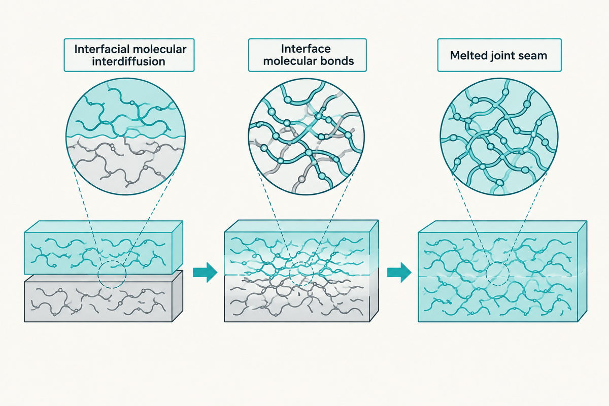
Plastic welding isn’t mechanical fastening, adhesive bonding, or solvent cementing. Rather, plastic welding melts the parent thermoplastic materials and homogenizes the interface, thus creating a molecular continuum. Thermodynamics and kinetics of the reactive polymer chains, the boundary between thermoplastic and thermosets, and the critical structural interface between the two components should be considered to understand the physics of the process.
Industrial Automation vs. Manual Hot Air & Extrusion Welding
For maintenance and prototype teams, understanding how processes are performed manually provides a point of reference and contrast. Field operations regularly implement hot air plastic welding, extrusion welding and handheld tools. Operators use either a plastic welder or heat gun fitted with either a nozzle or speed welding nozzles to join plastic pieces. In manual joining, a plastic welding rod or plastic filler rod is positioned in the seam and along even heating to deposit melted plastic in the groove. For long weld runs on geomembranes and plastic tanks, a continuously operating extruder feeds hot resin directly to the joint.
automotive bodyshop plastic repair often closes split car bumpers, cracked bumper covers and broken headlight tabs using a portable plastic welding kit or soldering gun, among other techniques. Reinforcing metal mesh (similar to window screen wire) or hot staples may be placed across the fracture seam, and filler material may be melted to effect a closure. Before attempting to weld plastics or weld pvc components, operators perform initial surface preparation to clean the joint seam. In polyvinyl chloride assemblies, technicians degrease the seam with acetone and lightly abrade the weld area with an abrasive pad or sand paper. After applying a preliminary tack weld to align components, the operator performs a steady pendulum welding or continuous speed welding. A skilled welder using professional plastic welding equipment may achieve reliable structural tank repair and roof membrane sealing, but manual welding technique methods exhibit higher operator dependency and less weld quality compared to automation.
Molecular Interdiffusion and Chain Reptation Kinetics
When two surfaces of thermoplastic polymers come into contact under pressure, heating initiates three stages of the welding process. The first stage is surface contact and thermal softening. The second stage is interdiffusion of the intermolecular chains across the weld interface. The final stage is either recrystallization or vitrification. The U.S. patent references de Gennes’ theory of reptation. It states that macromolecular chains are confined within tubular constraints of other macromolecular chains. Once the interfacial temperature exceeds the glass transition temperature (Tg) for amorphous resins, or the melting point (Tm) for crystalline resins, the macromolecular chains gain sufficient energy to escape the confinement tubes.
The molecular diffusion across the weld interface is modeled using Fick’s Law of Diffusion with constraints of reptation relaxation time, as characterized in NIST polymer chain diffusion studies.
Δx ≈ √(2 · D(T) · t)
Where D(T) is the temperature-dependent diffusion coefficient governed by the Arrhenius relationship D(T) = D0 · exp(-Ea / RT), Ea is the activation energy for chain motion, R is the universal gas constant, and t is the effective melt contact time. For a plastic weld joint to achieve full parent material tensile strength (measured according to ASTM D638 or ISO 13953), the interdiffusion distance Δx must exceed the average radius of gyration (Rg) of the polymer chains, typically between 5 and 25 nanometers. When Δx ≥ Rg, complete chain entanglement occurs, eliminating the physical boundary between the mating parts.
Thermoplastics vs. Thermosetting Polymers: Why Only Thermoplastics Can Be Welded
A major constraint of industrial plastic welding is that it applies only to thermoplastics. Thermoplastic polymers, which include polypropylene (PP), polyethylene (PE), acrylonitrile butadiene styrene (ABS), polycarbonate (PC), and polyamide (nylon), have linear or branched chains that are held together by secondary forces (van der Waals interactions, dipole-dipole interactions, and/or hydrogen bonding). When these polymers are subjected to heat, the secondary forces dissociate and the resins soften and become viscous liquids which can be deformed under pressure and solidify upon cooling.
Thermosetting polymers (like epoxies, phenolics, polyurethanes, and vulcanized rubbers) experience irreversible cross-linking during their initial curing process and, thus, form a permanent 3-D covalent network. Thermosets, on welding, can’t melt and flow; rather, thermal energy supports the break-up of covalent bonds and results in charring and outgassing. Consequently, thermosets can’t be joined by thermally fusing the joints; rather, mechanical fasteners or structural adhesives are needed.
| Polymer Classification | Molecular Structure | Thermal Response | Weldability Status | Common Industrial Examples |
|---|---|---|---|---|
| Linear Thermoplastics | Continuous unbranched macromolecular chains | Reversible melting; broad viscous flow zone | Excellent across all 5 thermal welding processes | HDPE, LDPE, PP, PVC, PMMA |
| Branched Thermoplastics | Linear backbone with lateral polymer side-chains | Reversible melting; slightly higher melt viscosity | Excellent; requires matched melt flow index (MFI) | LLDPE, branched Polypropylene |
| Engineering Amorphous | Randomly entangled chains; no crystalline lattice | Softens progressively above Tg; wide processing window | Ideal for ultrasonic and laser welding; predictable melt | PC, ABS, PS, SAN, PEI |
| Semi-Crystalline Resins | Ordered lamellar crystallites within amorphous matrix | Sharp melting point (Tm); rapid drop in melt viscosity | Requires high heat flux and shear joint designs | PA6, PA66, POM (Acetal), PBT, PEEK |
| Cross-Linked Thermosets | 3D permanent covalent networks | No melt phase; degrades and chars at elevated temperatures | Unweldable via thermal fusion; requires adhesive bonding | Epoxy, Phenolic (Bakelite), Polyurethane, Melamine |
Ultrasonic Plastic Welding: Acoustic Stack Mechanics, Frequency Selection, and Joint Energy Directors
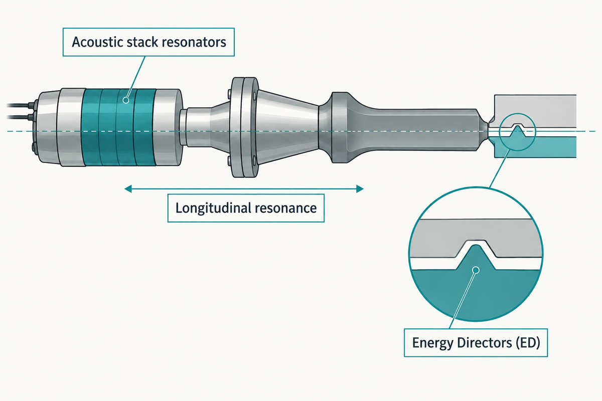
Ultrasonic plastic welding is the dominant joining method for small and medium volume thermoplastic assemblies and is especially suited to high volume assemblies. Ultrasonic welding converts electrical energy to mechanical vibratory motion of a transducer; the energy is then locally focused on the interface of the materials to be joined. The frictional and viscoelastic heating effect occurs in a few milliseconds.
The Acoustic Stack: Transducer, Booster, and Sonotrode Tuning
An ultrasonic plastic welding machine uses an acoustic stack consisting of three resonators operating in longitudinal resonance.
- Piezoelectric Converter (Transducer): uses ceramic PZT discs, and is designed to generate mechanical vibration from high frequency alternating voltage by means of an ultrasonic generator. The discs expand and contract axially, with an initial peak-to-peak amplitude of 10 to 20 μm.
- Acoustic Booster: A tuned resonant metal cylinder (machined from high-strength alloys such as titanium alloy Ti-6Al-4V or high-strength aluminum alloy 7075-T6) placed at its nodal (zero displacement) vibration plane. The Booster alters the amplitude of vibration transmitted from the converter by a precise mechanical ratio (e.g. 1:1, 1:1.5, 1:2.0, 1:2.5, etc.). This ratio is determined by the cross-sectional mass distribution between its input and output faces.
- Ultrasonic Horn (Sonotrode): This tooling horn fits directly against the upper plastic component. The horn is actuated by a pneumatic or servo-electric source of clamping force, and is used to induce vibrations into the workpiece. Weld horns are designed to displace uniformly in the axial direction by using Finite Element Analysis. This accounts for variations in design including tolerances. Using FEA accounts for abrupt changes in the cross-section of the horn and eliminates lateral or torsional vibration modes.
Operating frequency determines equipment size, power density, and part sensitivity. The standard industrial frequencies are:
- 15 kHz: High-power, large-amplitude systems (up to 4,000 W) capable of welding large parts (up to 350 mm joint perimeter) and softer polyolefins with high acoustic damping.
- 20 kHz: The industry workhorse frequency (1,000 W, 3,000 W), offering the optimal balance of power, amplitude (20–45 μm), and tool life for automotive interior trim, consumer appliances, and medical enclosures.
- 30 kHz to 35 kHz: Compact tooling systems used for packaging delicate medical devices and electronic housings, as well as laminates and films. Systems require a moderate input of energy.
- 40 kHz: Precision micro-welding systems (300 W, 1,000 W) operating with low amplitudes (10–25 μm), minimizing mechanical stress on sensitive internal subcomponents, fine wire coils, and micro-sensors.
Energy Director Geometry vs. Shear Joint Design
Since ultrasonic vibrations reduce rapidly through plastic bulk material, the joint interface must contain geometric stress concentrators to produce localized cyclic strain and interfacial melting. The two main joint configurations are the Energy Director and the Shear Joint.
Energy Directors (ED): Consist of a raised triangular ridge molded along the joint surface, normally with an apex angle of 60° or 90° and a height measured between 0.4 mm and 0.8 mm. Under acoustic vibration, mechanical stress concentrates at the sharp apex of the energy director, creating rapid localized hysteretic heating and melting before the bulk part softens. Energy directors are exceptionally effective for amorphous thermoplastics (such as ABS, PC, PMMA, and polystyrene) because these resins exhibit a broad glass transition range and retain high stiffness up to their softening point, following tuned geometric director principles in US Patent 6,896,754 B2.
Shear Joints: Failure to use shear joints when joining semi-crystalline polymers (such as nylon, polyoxymethylene (POM), polyethylene (PE), polypropylene (PP), etc.) can result from using traditional triangular energy directors. Polymers with a sharp melting temperature (Tm) and rapid decrease in melt viscosity allow the melt to flash-off and solidify upon contact with the colder resin surrounding it. To overcome this, engineers use a shear joint (interference joint), where vertical walls overlap with a controlled interference fit (0.2 mm to 0.5 mm). When the horn drives the upper member down, frictional shearing along the interface results in the melt of the polymer throughout the entire depth of engagement. This produces a strong, hermetically sealed weld with contained flash.
Shop-Floor Diagnostic: Horn Acoustic Resonance Drift
Shop-Floor Diagnostic—Horn Acoustic Resonance Drift: Swings in ambient temperature and continuous acoustic dissipation during extended, automated production cause the sonotrode to increase in temperature. Because the acoustic velocity of sound in titanium decreases by approximately 0.05% per °C, thermal expansion causes the horn’s natural resonant frequency to drift downward (often by 80 Hz to 180 Hz over an 8-hour shift). Modern digital ultrasonic generators feature automatic frequency tracking (PLL) within a ±500 Hz window; however, if horn heating exceeds this bandwidth, generator impedance mismatch triggers frequent overload trips, resulting in cold welds or incomplete joint penetration.
Hot Plate Welding: Heated Platen Thermal Cycles, Melt Transition, and Hermetic Pressure Vessels
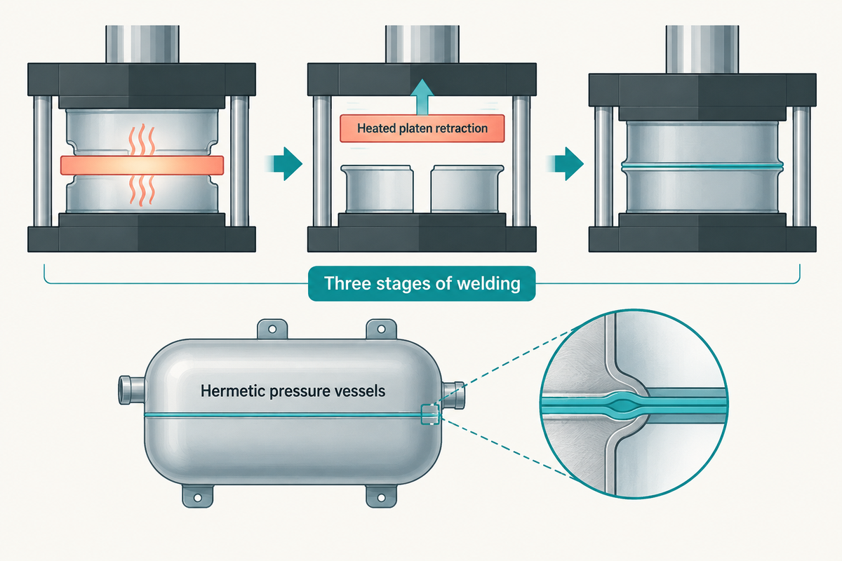
Hot plate welding is the leading industrial joining process for large, complicated, and heavy-walled thermoplastic components that require absolute hermetic sealing and high hydrostatic burst pressure. Commonly specified for automotive fuel tanks, under-hood coolant surge reservoirs and battery enclosures, as well as municipal polyolefin piping, hot plate welding provides structural weld strengths that can approach 100% of the parent material properties.
The Four-Phase Thermal Cycle Architecture
The welding cycle employs direct contact with a precisely heated metal platen (generally, aluminum-bronze or nickel-steel platen that’s maintained between 240°C and 420°C with an internal cartridge heater and closed-loop PID control). The process consists of four phases:
- Melt Phase (Heating under Controlled Displacement): The two plastic halves are clamped in custom-contoured upper and lower holding fixtures. The heated platen advances between the parts, and hydraulic or servo-electric actuators press the joint surfaces against the platen faces. Heating occurs in two sub-steps: an initial flash melt under light contact pressure (0.1–0.3 MPa) to overcome injection-molding part warpage and establish uniform contact, followed by a soak melt under near-zero pressure, allowing heat to conduct deeply into the polymer wall (typically 1.0 mm to 2.5 mm melt depth).
- Changeover Phase (Platen Retraction): Changeover time must be strictly minimized (1.5-3.0 seconds) to prevent oxidation of the polymer surface, and cooling of the melt. The molten interfaces are brought together by rapid retraction of the holding fixtures. The heated platen also retracts from the center of the machine. If highly oxidizable resins, such as PA66 and POM, are being joined, a non-contact infrared platen or a nitrogen purge blanket is used in addition to minimize oxidation.
- Joining and Squeeze Phase: Once the holding fixtures bring the interfaces into contact, the facing joints are forged together by applying pressure (0.2-0.6 MPa) by the actuators. Modern machines use mechanical hard stops or servo-encoder position control to effect the squeeze. This is much more reliable than relying on pressure control to effect the desired displacement and prevents excessive squeezing out of the core polymer.
- Cooling and Solidification Phase: Parts remain clamped under pressure for 8-25 seconds to let the molten interface cool down to a temperature below its Tc or Tg. Holding force during crystallization prevents the formation of voids, and counters the volumetric shrinkage of the polymer.
Why Hot Plate Welds Outperform Other Methods in Hydrostatic Burst Pressure
Although ultrasonic, and piezoelectric welding use rapid, localized friction to produce molecular alignment in the flow direction, hot plate welding is based on the concept of static macromolecular chain interdiffusion in a deep thermally molten pool. During the squeeze phase, deep macromolecular reptation occurs across the wall thickness of the joined part.
In hydrostatic burst testing conducted according to ASTM D1599 and tensile testing under ISO 13953, hot plate welded joints on high-density polyethylene (HDPE) and polypropylene (PP) pressure vessels consistently achieve 95% to 100% tensile weld factor (the ratio of joint tensile strength to virgin parent wall tensile strength). In destructive hydrostatic pressure testing of automotive coolant reservoirs, failure frequently occurs in parent injection-molded sidewalls rather than along welded parting lines under qualified welding parameters, with test assemblies withstanding hydrostatic pressures exceeding 20 bar.
Laser Plastic Welding: Contour and Quasi-Simultaneous Transmission Joining (TTIr)
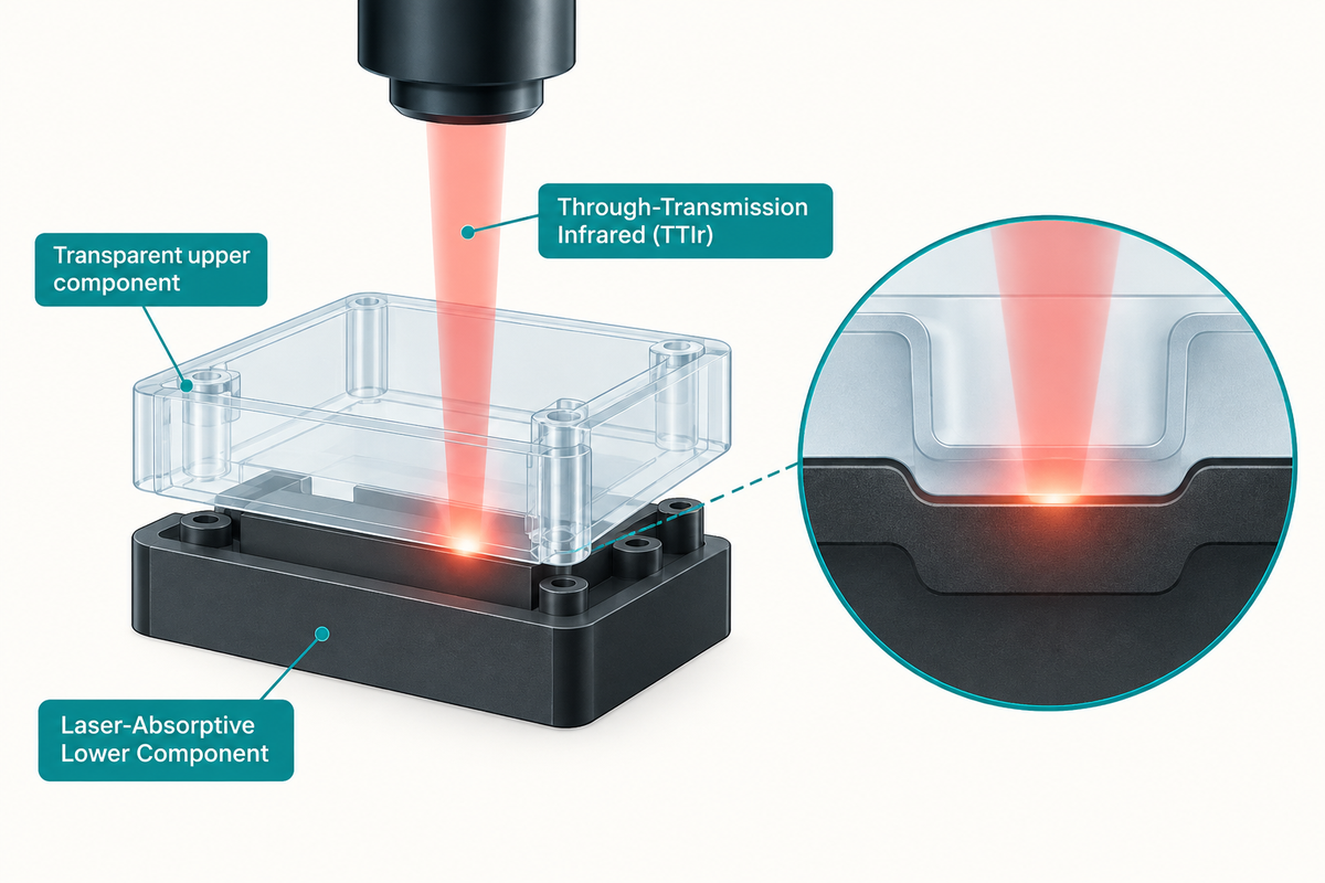
Laser plastic welding offers the highest aesthetic quality in micro-particle-free joining of high-reliability medical devices, microfluidic devices, and automotive radar sensors. Monochromatic laser light in the near infrared (NIR), 808 nm, 940 nm, 980 nm, 1070 nm, is used to provide pinpoint thermal energy, in the absence of vibration, acoustic shock or surface marking.
Through-Transmission Infrared (TTIr) Physics
Nearly all industrial laser plastic welding relies on the Through-Transmission Infrared (TTIr) principle. The assembly requires a specific optical pairing between the two mating halves.
- Laser-Transmissive Upper Component: Must exhibit high optical transmittance (≥40% to 50%) at the laser wavelength. Engineering resins in their natural, unfilled state (such as natural PC, PMMA, COC and COP) provide good through-transmission in the near-IR spectrum.
- Laser-Absorptive Lower Component: Must absorb the incident laser energy within a thin surface boundary layer (typically 50 μm to 200 μm deep). This is traditionally achieved by compounding the lower plastic with 0.2% to 0.5% carbon black pigment.
During the welding cycle, the laser beam passes through the transparent upper component with insignificant thermal dissipation. The absorbed radiation at the lower component, produces heat and melts the component, which results in formation of a weld seam at the mating interface. A clamping pressure is usually applied using an optical glass clamping plate or a custom pneumatic nest, conforming to workholding safety criteria in ISO 16156.
Clear-to-Clear Joining and Near-Infrared Absorbers
Frequent manufacturing issues, with welding assemblies where both components need to remain optically transparent (such as medical diagnostic cartridges, fluid level sight glasses, and microfluidic lab on chip assemblies) arise due to the fact that standard carbon black can’t be used because of visibility discoloration.
To surpass this limitation, engineers use advanced near-infrared (NIR) specialized dye absorbers (for instance, quaterrylene based Lumogen IR or squaraine based dye formulations). These special chemicals have very intensive and narrow absorption peaks matching certain diode lasers wavelengths (i.e. 808 nm or 980 nm) and have near zero absorption in visible wavelengths (400-700 nm). When these absorbers are used as localized surface coatings or added in low amounts (10-50 ppm) to the lower molded component, manufacturers can produce high-strength, hermetic welds while retaining optical transparency at visible wavelengths.
Beam Delivery Architectures: Contour vs. Quasi-Simultaneous Scanning
There are four main configurations for delivery of the laser beam in plastic welding machines:
- Contour (Point-by-Point) Welding: A focused laser beam mounted on a multi-axis CNC gantry or articulated robotic arm moves along the joint path at speeds between 10 and 100 mm/s. Best suited for large 3D automotive exterior components and low-volume flexible production.
- Quasi-Simultaneous Welding: High-speed galvo-mirror scanning heads in laser beam steering direct the laser beam repeatedly along the entire 2D weld contour at speeds between 2,000 and 10,000 mm/s and complete 15 to 40 passes per second. Before the polymer cools, the entire weld path is traversed and the joint seam melts. This permits vertical part collapse (0.1 mm to 0.5 mm) under continuous servo clamping. This architecture is dominant in consumer electronics and automotive sensor packaging.
- Simultaneous Welding: Employs multiple stationary diode laser modules arranged around the perimeter to illuminate the entire joint line at once, achieving cycle times under 1 second for small symmetrical parts. This design is used to weld small and symmetric parts in less than 1 second.
- Mask Welding: A collimated line beam sweeps across a precision metal stencil mask placed over the workpiece, exposing designated perimeter sealing lands around delicate microfluidic channels (down to 100 μm width) to laser radiation without requiring expensive galvo programming. This is used for very small features on devices like microfluidic channels.
Linear and Orbital Vibration Welding: Heavy-Duty Structural Friction Joining
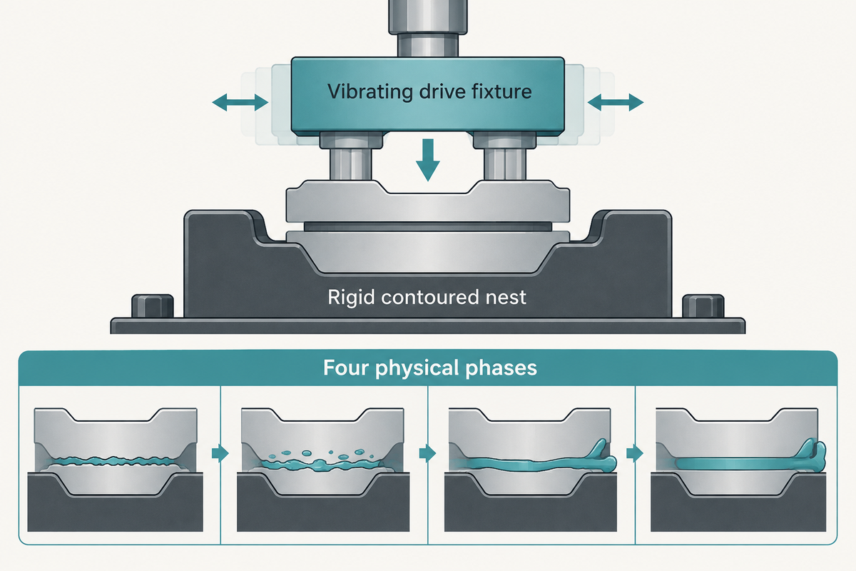
Vibration welding (also referred to as friction welding) is a high-energy joining process used for medium to large thermoplastic structures where cycle times must be less than 10 seconds. It’s the predominant manufacturing process for automotive air intake manifolds and other similar structures.
Frictional Heat Generation and the Four Physical Phases
In a linear vibration welding machine, the lower plastic component is rigidly secured in a contoured nest, while the upper component is clamped in a massive vibrating drive fixture. An electromagnetic drive system oscillates the upper part against the lower part under static vertical clamping force (generally 0.5 to 2.5 MPa). The oscillation operates at a resonant frequency of 100 Hz to 240 Hz with a peak-to-peak linear displacement (amplitude) of 0.7 mm to 1.8 mm.
The vibration welding process proceeds through the following four physical phases:
- Phase 1: Solid Friction and Asperities Wear: Dry Coulomb friction between the surface asperities rapidly removes heat. Polymer approaches its glass transition temperature or melting temperature. Bulk polymer is solid and no molten material exists. Part collapse is insignificant.
- Phase 2: Unsteady Melt Transition: Interfacial temperature exceeds Tg or Tm. The first layer of melt is formed, Coulomb friction along the interface is replaced by hydrodynamic shear, and the film rapidly thickens. Part collapse occurs in the vertical direction.
- Phase 3: Steady State Flow: Thermal generation of melt and the lateral flow of molten polymer from the interface are balanced, resulting in a dynamic equilibrium. The thickness of the melt film is constant (0.25 mm to 0.50 mm) and the collapse rate is linear under constant clamping force.
- Phase 4: Solidification under Holding Pressure: The electromagnetic drive shuts off, and the vibrating fixture is centered to the zero position in less than 50 milliseconds. Vertical clamping pressure is maintained or increased for 2 – 5 seconds. The joint interface is consolidated, and the center of the molten core is solidified to form a high strength structural bond.
Linear vs. Orbital Vibration Mechanics
While linear vibration, requires part clearance in the direction of vibration, orbital vibration welding, drives the upper tool in an eccentric circular or elliptical path, at a frequency of 200 – 300 Hz and with a small orbital radius (0.3 – 0.8 mm). It’s well suited for making joints in round parts and components.
Since vibration welding expels a significant amount of molten flash in Phase 3, joint design must include internal and external flash traps (weld Flash Pockets) to capture expelled molten materials. These prevent contamination of the automotive fluid by particulate matter, maintaining weld tensile integrity verified per ASTM D638.
Heat Staking and Hot Melt Insertion: Precision Thermal Boss and Threaded Insert Assembly
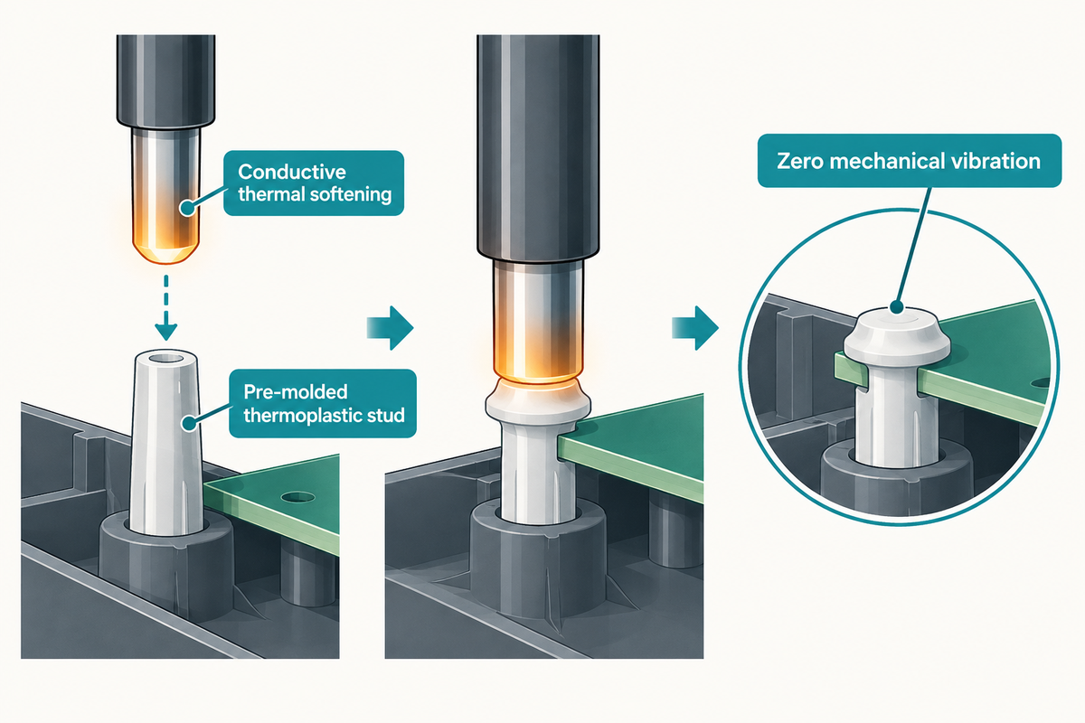
Ultrasonic, hot plate, laser and vibration welding predominantly join two plastic surfaces together along a continuous perimeter seam. While heat staking and Hot Melt Insertion are two thermal forming processes to join dissimilar materials (most in particular Printed Circuit Boards, stamped metal brackets and decorative trim, and threaded brass fasteners to plastic Housings).
Thermal Staking Physics: Direct Conduction vs. Acoustic Shock
In a heat staking system, a pre-molded thermoplastic stud (boss) extends up through a clearance hole in a mating part (e.g. an electronic circuit board or stamped aluminum frame). A precisely heated metal forming tool (termed a thermode or staking punch ), machined from beryllium copper, brass, or tool steel and maintained at a controlled temperature (typically 180°C to 380°C depending on resin), advances downward via a controlled pneumatic or servo cylinder. The punch is maintained at a temperature of about 180°C to 380°C, based upon the resin used.
The process combines conductive thermal softening with mechanical compression:
- As the punch contacts the top of the plastic boss, heat flows directly into the resin.
- As the plastic softens to above its glass transition temperature or melting point, downward force reshapes it into a retaining head (dome, rosette, knurled, or a flush profile).
- In sophisticated thermal staking systems, compressed cooling air is pulsed through the tool tip while holding pressure. This solidifies the plastic head before tool retraction, thereby eliminating spring-back and residual stress.
Most significantly, heat staking creates zero mechanical vibration and zero acoustic shock waves. In contrast, ultrasonic staking of electronic subassemblies often results in catastrophic micro-cracking of delicate surface-mount device (SMD) ceramic capacitors, breaking wire-bonds in MEMS sensors, and fracturing sensitive printed circuit traces. Heat staking offers complete process safety for high-reliability automotive electronic devices and medical monitoring devices.
Hot Melt Threaded Insert Installation
When assemblies require frequent field disassembly, direct tapping of threads into plastic leads to premature thread stripping and creep failure. Hot melt insertion provides permanent, high-strength metallic female threads by embedding knurled, brass or stainless-steel threaded inserts in pre-cored molded holes.
The heated insertion tip transfers thermal energy through a brass insert. As the operator or automated feeder presses the insert down, plastic surrounding the brass insert melts and flows into the insert’s external diagonal, helical, knurls and a circumferential undercut. Cooling the plastic permanently locks the insert in place. This provides excellent pull-out retention force (Fpull) and torsional resistanace to turn-out (Ttorque) , calculated by:
Fpull = π · dinsert · Lengagement · τshear
Where dinsert represents the outer diameter of the insert, Lengagement is the embedded axial length, and τshear is the ultimate shear strength of the solidified parent polymer, experimentally verified via standardized pull testing under ASTM D638.
Recommended for manufacturing facilities requiring dependable benchtops or automated insertion machines, we offer an extensive line of standard heat staking machines for high-precision thermal boss forming and installation of threaded inserts.
Direct 5-Way Engineering Comparison: Cycle Time, Joint Strength, Flash Generation, and Capex
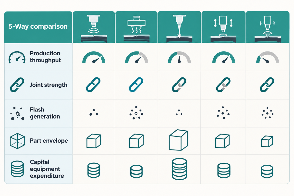
Selecting the right plastic welding technology requires balancing the mechanical performance requirements against the production throughput, part geometry, resin system, and the available capital budget. The comparative matrix below provides some useful quantitative benchmarks, with joint tensile factors normalized against parent material properties under ASTM D638.
| Engineering Parameter | Ultrasonic Welding | Hot Plate Welding | Laser Plastic Welding (TTIr) | Vibration Welding (Linear/Orbital) | Heat Staking & Hot Melt Insertion |
|---|---|---|---|---|---|
| Typical Cycle Time | 0.2 – 1.5 seconds | 15 – 45 seconds | 1.0 – 15 seconds | 3.0 – 10 seconds | 1.5 – 5.0 seconds |
| Weld Joint Tensile Strength (% of Parent) | 70% – 90% (amorphous) 60% – 80% (crystalline) |
95% – 100% (highest tensile recovery) | 80% – 95% (clean, high-density interface) | 85% – 95% (high structural integrity) | Mechanical capture: 85%–100% of stud shear yield |
| Hermetic Pressure Sealing Rating | Moderate (0.5 – 3.0 bar); vulnerable to micro-channels | Excellent (exceeding 20 bar burst pressure) | High (2.0 – 10.0 bar hermetic seals) | Good to High (3.0 – 8.0 bar with flash traps) | N/A (discrete boss fastening, not perimeter seal) |
| Part Size Capacity | Small to Medium (max joint perimeter ~300–350 mm) | Medium to Extremely Large (up to 1,500 × 800 mm) | Small to Medium (up to 400 × 400 mm galvo field) | Medium to Large (up to 1,200 × 600 mm) | Single points to multi-station arrays (up to 60+ bosses) |
| Flash & Particulate Generation | Low to Moderate; particulate dust common | High external/internal bead flash (requires squeeze control) | Zero flash, zero particulates (cleanroom optimal) | Moderate to High flash ribbons (requires traps) | Zero particulate flash; smooth reformed head |
| Vibration / Shock to Internal Components | High (15–40 kHz acoustic shock risks PCB damage) | None (static thermal contact) | None (optical laser beam delivery) | Severe (100–240 Hz mechanical oscillation) | Zero (static thermal conduction; PCB-safe) |
| Tooling Wear & Maintenance | Moderate; titanium horn acoustic fatigue / erosion | Moderate; platen PTFE coating re-application needed | Low; non-contact laser beam; clamping glass cleaning | High; heavy mechanical springs, bearings, wear plates | Low to Moderate; heated thermode tip replacement |
| Polymer Flexibility | Best on amorphous; requires shear joints for crystalline | Outstanding on polyolefins (PP, PE, TPO) | Requires optical pairing (transmissive + absorptive) | Excellent on filled nylon, PP, and structural resins | Universal across all meltable thermoplastics |
| Equipment Capital Cost (Capex) | $15,000 – $60,000 (standard benchtop/servo) | $45,000 – $180,000 (hydraulic/servo platen systems) | $60,000 – $250,000+ (laser source + galvo head) | $75,000 – $220,000 (electromagnetic drive frame) | $12,000 – $55,000 (modular benchtop to multi-head) |
| Tooling & Fixture NRE Cost | $3,500 – $12,000 per horn/nest set | $8,000 – $25,000 (matched heated platen + nests) | $5,000 – $18,000 (custom clamp glass + nest) | $12,000 – $35,000 (heavy cast/machined nests) | $2,000 – $8,000 (custom thermode heads + fixture) |
Polymer Compatibility Matrix: Crystalline vs. Amorphous Resin Behavior and Glass Transition Limits
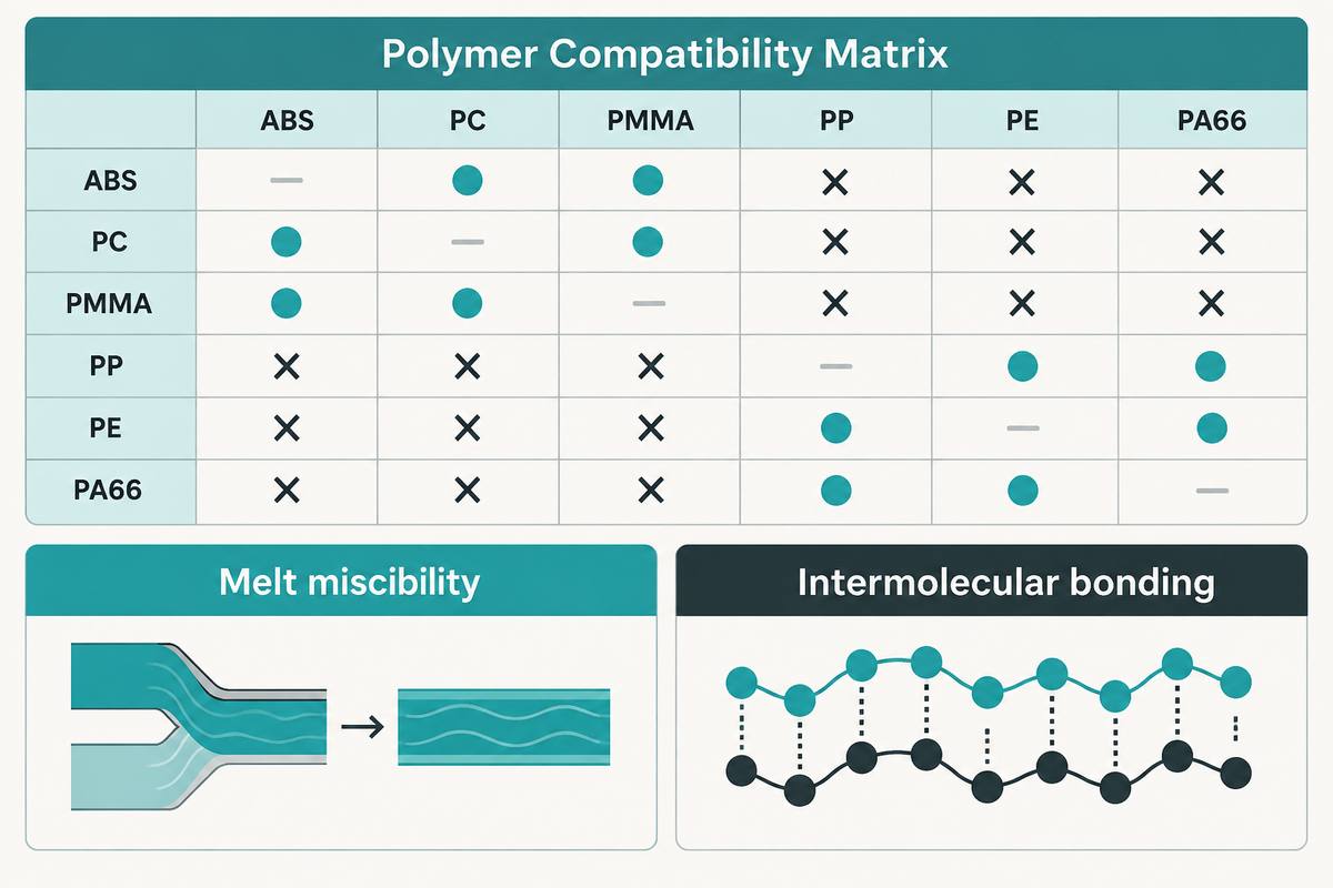
One of the essential engineering judgments in plastic welding is whether two similar or two dissimilar thermoplastics can be successfully welded. Three primary thermodynamic and rheological criteria govern the chemical compatibility of polymer solubility and molecular interdiffusion: solubility parameters, thermal transition, and melt flow.
Thermodynamic Criteria for Dissimilar Polymer Welding
If the two dissimilar thermoplastic resins are miscible in the melt state, a strong molecular bond can be attained if the macromolecular chains of the two resins are mutually soluble. The Hildebrand solubility parameters of the two resins must be within 1.5 units, i.e. ΔΔ ≤ 1.5, matching interdiffusion thermodynamics characterized by the NIST Polymer Physics Division.
Δδ = |δ1 - δ2| ≤ 1.5 (cal/cm3)1/2
When ∆∆ ≤ 1.5, the two polymers can interdiffuse in the melt state and form molecular bonds at the interface. In addition, the glass transition temperatures or melting points of the two polymers shouldn’t differ by more than 30°C to 40°C . If the thermal transition temperatures of the two polymers differ too much, the polymer with the lower thermal transition will severely degrade and outgas before the higher-temperature polymer reaches its melt viscosity.
| Base Resin | Resin Structure | Tg / Tm (°C) | Compatible Resins for Welding | Incompatible Resins (Zero Weld Strength) |
|---|---|---|---|---|
| ABS | Amorphous | Tg ≈ 105°C | ABS (self), PC (excellent), PMMA, SAN, PVC | PE, PP, PA6, PA66, POM, PEEK |
| Polycarbonate (PC) | Amorphous | Tg ≈ 145°C | PC (self), ABS (excellent), PMMA, PBT (modified) | PE, PP, POM, PVDF, Fluoropolymers |
| PMMA (Acrylic) | Amorphous | Tg ≈ 105°C | PMMA (self), ABS, PC, PVC | PE, PP, Polyamides, POM |
| Polystyrene (PS / HIPS) | Amorphous | Tg ≈ 95°C | PS (self), HIPS, SAN | PC, Polyamides, Polyolefins, POM |
| Polypropylene (PP) | Semi-Crystalline | Tm ≈ 165°C | PP (self), TPO, EPDM-modified PP, PE (limited) | ABS, PC, PMMA, PA6, PA66, POM, PS |
| HDPE / LDPE | Semi-Crystalline | Tm ≈ 130°C | PE (self), LLDPE, UHMWPE (compression weld) | All styrenics (ABS/PS), PC, Acrylics, Polyamides |
| Polyamide 6 / 66 (Nylon) | Semi-Crystalline | Tm ≈ 220°C / 260°C | PA6 (self), PA66 (self), PA6 to PA66 (moderate) | Polyolefins, Polycarbonate, Styrenics, POM |
| POM (Acetal / Delrin) | Semi-Crystalline | Tm ≈ 175°C | POM (strictly self-welding only) | All other engineering and commodity plastics |
| PEEK | High-Temp Semi-Crystalline | Tm ≈ 343°C | PEEK (self), PEI (limited high-temperature TTIr) | All commodity and standard engineering resins |
Quality Inspection and Defect Prevention: Flash Traps, Cold Welds, Degradation, and Ultrasonic NDT
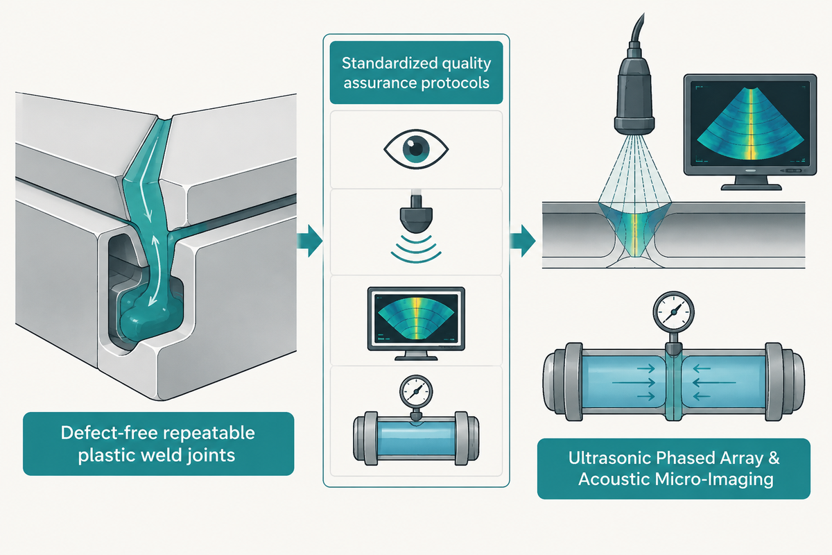
Defect-free repeatable plastic weld joints in zero-defect automotive, aerospace and medical production require in-depth knowledge of joint failure mechanisms, geometric defects, as well as advance non-destructive testing (NDT) techniques.
Primary Defect Root Causes and Corrective Actions
- Cold Welds (Incomplete Fusion): This happens when the interfacial polymer doesn’t reach adequate melt temperature or not sufficient holding time is allowed for chain reptation. In ultrasonic welding, cold welds may be due to insufficient amplitude, power cut-off of the generator or worn horn faces. In hot plate welding, an excessive changeover time (>3.5s) allows the molten film to oxidize and freeze before mating. Remedy: Increase the acoustic amplitude, reduce the changeover speed of the platen (<2.5s), and verify the calibration of the thermocouples.
- Molten Core Squeeze-Out (Over-Pressurization): A common myth on the shop floor is that increasing weld clamp pressure results in a stronger joint. Increasing squeeze pressure beyond the yield pressure of the polymer results in squeezing out the entire molten polymer and leaving a thin, cold and highly oriented and anisotropic polymer layer, which leads to brittle joints and failure by notch sensitive fracture. Remedy: Transition from pressure only control to a mechanical limit displacement, limiting melt collapse to 0.3-0.6 mm.
- Thermal Degradation and Polymer Burning: Caused by excessive platen temperatures, prolonged ultrasonic weld cycles, or excessive laser irradiance. Overheating cleaves polymer covalent backbones, generating carbonaceous char, monomer vapor bubbles, and embrittlement. Remedy: Lower platen temperatures to within 30°C, 50°C above Tm, tune laser scanning velocity, and incorporate nitrogen shielding.
- Internal Voids and Cavitation: Semi-crystalline polymers shrink volumetrically by 8% to 15% during crystallization. If holding pressure is removed before the weld core solidifies, internal vacuum voids form, drastically reducing fatigue life. Remedy: Extend holding and solidification time under pressure by 30%–50%.
Non-Destructive Testing (NDT) and Destructive Validation
To ensure joint integrity without scrapping expensive assemblies, advanced production lines perform standardized quality assurance protocols:
- Ultrasonic Phased Array & Acoustic Micro-Imaging: The use of High-frequency ultrasonic testing (5 MHz to 50 MHz) sends acoustic waves through the weld seam. Real time imaging enables detection and mapping of various micro-defects.
- Optical Laser Shearography: Phase-stressed interference fringe patterns are used to detect sub-surface defects. A mild thermal or pressure stress is applied to the welded part while the joint line is illuminated by a coherent laser.
- Destructive Hydrostatic Burst and Tensile Testing: Batch validation has been performed using ASTM D638 (tensile pull tests at a rate of 50 mm/min) and ASTM D1599 (pressurizing hollow components to hydraulic burst failure). In high quality joints, failure must occur in the parent material rather than failure occurring along the weld parting line.
Equipment Selection, Custom Automated Workcells, and SIMITCH Hot-Melt Integration
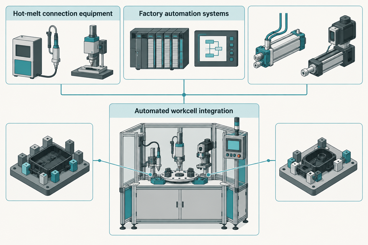
Transitioning from prototyping to full-scale production involves aligning the automation and control of machinery with the desired throughput and geometry of manufactured parts. Industrial production equipment generally falls within three main operational categories:
- Manual Benchtop Systems: Single-station, operator-loaded machines using pneumatic actuators, two-hand safety touch buttons, and digital PLC controllers compliant with ISO 16156 machinery safety standards. Ideal for low-to-medium volume production (1,000–50,000 parts/year), laboratory R&D, and cleanroom cell assembly.
- Semi-Automated Rotary Dial Indexing Tables: include 4, 6, or 8 position cam or servo-controlled rotary tables. Operators or SCARA pick-and-place robots load parts at Station 1; subsequent stations execute automated component presence verification, multi-point thermal staking or ultrasonic welding, vision-based flash inspection, and automated good/bad part sorting. Throughput ranges from 300 to 1,200 parts per hour.
- Fully Automated Multi-Axis Robotic Workcells: Integrated inline workcells featuring 6-axis articulated robots, precision servo-electric presses, continuous linear optical encoders, high-resolution machine vision, and real-time SPC data logging. Welds are monitored via closed-loop distance-energy-power curves, storing full traceability data for IATF 16949 automotive and ISO 13485 medical device compliance.
Customizations, special thermal assembly architectures, and different factory automation systems are supported by high-precision hot-melt connection equipment manufactured by SIMITCH.
To create high-precision factory automation systems, look into our hot-melt connection equipment and standard heat staking machines. For multi-station production lines, look into our automated precision assembly systems and learn more about SIMITCH corporate history and technical expertise. For tooling design, contact our engineering team at SIMITCH.
Frequently Asked Questions About Plastic Welding Processes
Can all types of plastics be welded together?
Thermal plastic fusion is accomplished using thermoplastic resins. Other resins, such as cured epoxies, vulcanized rubber, and phenolics, contain 3D covalent cross-links and decompose to char and outgas rather than melt when heated. In addition, when attempting to weld two different thermoplastics together, the materials must share chemical compatibility, matching Hildebrand solubility parameters within 1.5 (cal/cm3)1/2, and exhibit overlapping thermal transition windows within 30°C to 40°C. Pairings such as polyethylene and polycarbonate or nylon and polypropylene have no interfacial attraction and therefore no weld strength, and the joints fail under load.
What is the primary difference between ultrasonic plastic welding and heat staking?
Ultrasonic welding uses high-frequency acoustic vibration (15–40 kHz) to create interfacial friction within 0.2 to 1.5 seconds. Heat staking uses a thermode punch to heat and reform plastic bosses to create mechanical connections or insert threaded fasteners to components. This process doesn’t use vibration and protects fragile printed circuit boards and surface-mount ceramic components from acoustic shock.
Why does hot plate welding take longer than vibration welding but provide superior pressure sealing?
Hot plate welding relies on direct thermal conduction from an electrically heated metal platen, requiring a staged cycle consisting of thermal melt soak (8 to 20 seconds), rapid platen retraction changeover (1.5 to 3 seconds), and consolidation under clamp pressure (10 to 25 seconds). This extensive thermal exposure produces a deep, stress-free molten boundary layer with complete molecular chain reptation across the entire joint wall thickness. In contrast, vibration welding generates friction rapidly within 3 to 10 seconds, but induces severe directional molecular alignment and expels flash along the oscillation axis. In high-pressure fluid reservoirs and fuel tanks tested under ASTM D1599, the isotropic, deeply diffused bond of hot plate welding provides superior resistance to micro-channel porosity and hydrostatic burst leakage exceeding 20 bar.
How can two completely transparent plastic parts be welded using a laser without burning?
Through-Transmission Infrared (TTIr) laser welding joins clear parts by applying specialized near-infrared (NIR) dye absorbers (such as Lumogen IR formulations) to the joint interface. These chemical dyes absorb specific diode laser wavelengths (808 nm to 980 nm) while remaining completely transparent in the visible light spectrum (400–700 nm).
What is the most common cause of plastic weld joint failure on industrial assembly lines?
The main reason for weld joint failure in production is excessive clamp squeeze pressure, which expels the molten polymer into flash and leaves a cold, brittle, boundary layer. Other reasons include using the wrong Energy Director for a semi crystalline resin (which freezes prematurely), mold release agent build-up, and long platen change-over times.
References & Sources
- ASTM D638-14(2022): Standard Test Method for Tensile Properties of Plastics. ASTM International, West Conshohocken, PA.
- ISO 13953:2024: Polyolefin pipes and fittings, Determination of tensile strength and failure mode of test pieces from a butt-fused joint. International Organization for Standardization, Geneva.
- ASTM D1599-18: Standard Test Method for Resistance to Short-Time Hydraulic Pressure of Plastic Pipe, Tubing, and Fittings. ASTM International.
- ISO 16156:2004 / ISO/WD 16156: Machine-tools safety, Safety requirements for the design and construction of workholding equipment.
- NIST Polymer Physics Division: Chain Reptation, Relaxation, and Interfacial Molecular Interdiffusion Models.
- Assembly Magazine: Understanding and Selecting the Right Process for Plastic Part Assembly; Heat Staking vs. Ultrasonic Welding for PCB Assemblies. BNP Media.
- Plastics Decorating: Improving Plastic Welding: Learn to Think Like Molten Plastic; Plastic Welding Myths and Realities. Peterson Publications.
- Plastics Technology (PTOnline): Fundamentals of Plastic Laser Welding & Near-Infrared Absorbers. Gardner Business Media.
- US Patent 6,896,754 B2: Method and apparatus for ultrasonic welding of thermoplastic parts with tuned energy director geometry. USPTO.


WHY WE WRITE THIS
About SIMITCH
SIMITCH develops sheet-metal joining equipment for clinching, riveting, servo pressing, pneumohydraulic drive and hot-melt connection applications. Our engineering team starts with the material stack, access envelope, cycle target and acceptance method before recommending a machine route.
Founded in 2006 in Taicang, Jiangsu, SIMITCH combines research and development, in-house production and global sales. These guides turn field experience into practical decision support for process engineers, plant teams and industrial buyers.
OUR EXPERIENCE
Since 2006
Equipment engineering, machining, assembly and joint validation under one manufacturing system.
OUR EXPERTISE
Five joining routes
Clinching, riveting, SPR, precision press-fit and hot-melt connection for production lines.