Get in touch with Suzhou Simitch Machinery Co., Ltd Company


Updated September 2026
Self-piercing riveting SPR machines are systems that set semi-tubular rivets into assembled layered materials, but a machine name or force rating can’t determine if a production joint will function. The joint’s feasibility begins with the sheets, the order of the sheets, die-side access, and the evidence offered by the completed joint. Equipment selection comes later, and the joint must be revalidated with the target process.
Terminology boundary: In this guide, self-piercing rivet equipment or riveting equipment means the complete riveting system: machine, feed, tooling and consumable. Suppliers may describe portable formats as SPR rivet guns, while fixed cells serve OEM production lines. Application briefs often discuss body-in-white structural components and EV battery trays, but every sheet metal stack still needs proof. Compared with spot welding and other mechanical joining routes, rivet installation can join dissimilar materials and multiple layers of material without pre-drilling; choosing the right rivet and die remains a joint quality decision.
Direct answer: In conventional self-pierce riveting, the rivet pierces the upper layer or layers and flares into the die-supported lower sheet, normally without a predrilled hole. A reliable project does not jump from that definition to a machine quote. It screens the complete stack, maps access, runs a controlled trial, inspects sectioned joints, performs the required mechanical tests, correlates production signals, and only then fixes the equipment and control architecture.
Keep these five boundaries visible
- No pre-hole doesn’t imply one-sided access. Conventional SPR still requires a die and a reaction path behind the lower sheet.
- Even a pair of materials isn’t a qualified stack. Grade, thickness, order, coating, adhesive, and local geometry all matter.
- Good appearance doesn’t guarantee strength. Appearance, cross-section, and mechanical testing all uniquely answer different questions.
- Even a clean force-displacement trace is not a final inspection. Some physical defects remain outside of the signal window.
- Trial-machine proof isn’t automatically transferable. The tooling and motion profile of the final riveting system must be revalidated.
How Conventional SPR Forms a Joint Without a Predrilled Hole
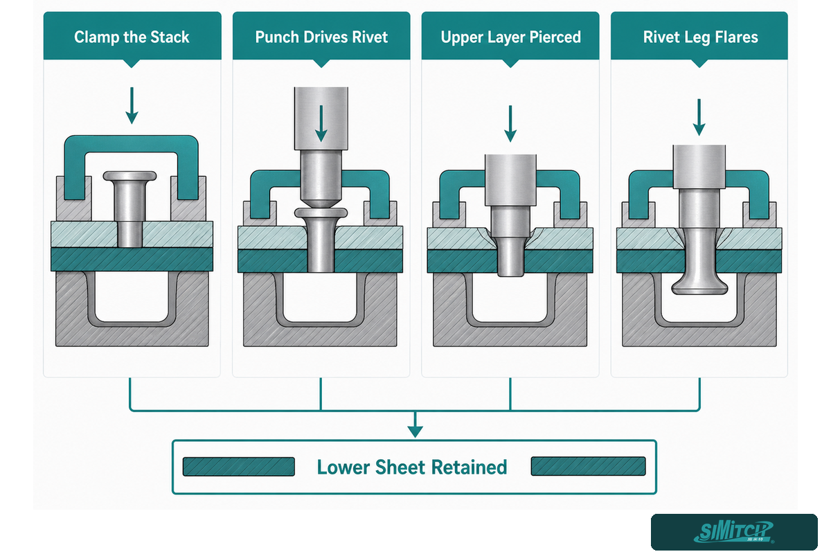
A self-piercing rivet is placed over the stack and is supported by a matched die on the lower side. The clamp or blankholder controls and supports the stack. The punch drives the rivet, but the intended process stops short of piercing the bottom layer of the stack. Material flow in the die flares the rivet leg. This flare captures the lower-sheet material and creates the mechanical interlock.
One peer-reviewed process study identifies four main steps in the process: clamping, piercing, flaring and release. Cold-forming and mechanical fastening techniques are employed in this process, whereas welding fusion isn’t. There’s no weld nugget, and a typical process doesn’t require a drilling step along with chip control, which is characteristic of a conventional through-hole fastener. Thus, this process may be useful in multi-material assembly, including some combination of aluminum and high strength steel stacks, once the actual combination is proven.
The lower sheet serves two functions. It must allow flaring of the rivet leg without uncontrolled cracking, and it must provide sufficient material to maintain the interlock. For this reason, the result may change by flipping the two sheets. The die also forms a button on the side of the assembly, and thus the first consideration of this design may include cosmetic and packaging issues.
The no-pre-hole statement needs one qualifier
“No predrilling” is an accurate statement for semi-tubular SPR processes, and it shouldn’t be generalized to other specialized processes. For instance, a 2025 study specifically examines conventional and pre-hole SPR for a difficult composite-to-steel application, and compares the two. As a first step in a typical screening process, the conventional approach should be followed. For a brittle composite or an unusual stack that demands a different approach, the variation and justification of a separate process should be given, rather than sheltering the approach behind a broad SPR definition.
Key takeaway
Conventional SPR avoids a separate pre-hole, but it still depends on controlled clamping, a matched die, lower-sheet integrity and access to both sides of the joint location.
Start With the Stack: The Feasibility Gate
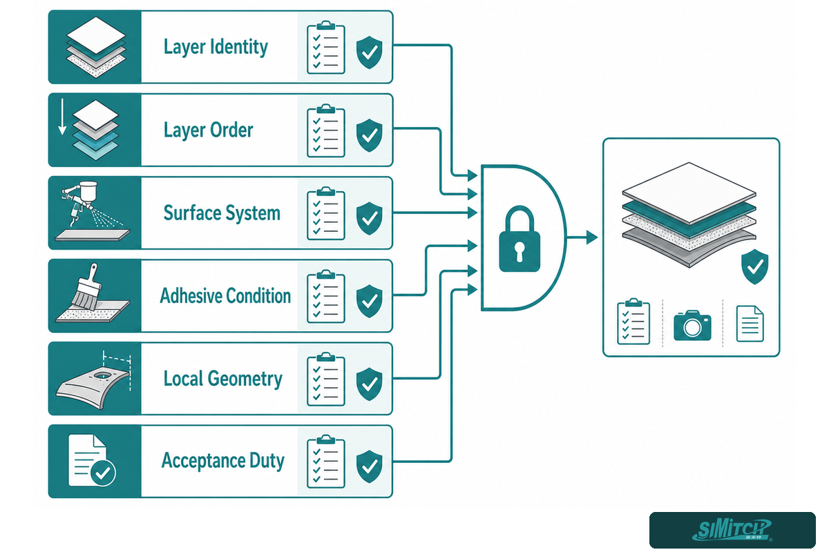
“Can SPR join aluminum to steel?” is far too general to approve the launch of a machine or production methods. The actual question is: can this rivet and die combine to produce an acceptable joint in the sequence defined in the drawing, at this location, with the manufacturing and service conditions stated?
Peer-reviewed papers on measurements of joint sections indicate that engineers select a rivet and die combination for a particular joint sequence, fabricate sample joints, and assess characteristics such as head position, interlock, and the thickness of the remaining bottom sheet. The study also warns that familiar linear interlock measurements do not perfectly predict joint strength. For this reason, screening of the stack represents a necessary step in the assessment of joint design, and is certainly not a step that can be omitted.
The Stack-to-Joint Feasibility Gate
| Gate input | What to record | What can fail if it stays vague |
|---|---|---|
| Layer identity | Grade, temper, thickness and tolerance for every layer | A coupon represents different material from production |
| Layer order | Punch-side and die-side sequence | The rivet pierces or flares into the wrong material behavior |
| Surface system | Coating, lubricant, cleanliness and permitted marking | Friction, appearance or corrosion behavior changes |
| Adhesive condition | Type, bead, uncured/cured state and squeeze-out boundary | The hybrid joint is tested under the wrong process condition |
| Local geometry | Flange width, edge distance, curvature, nearby features and joint pitch | The coupon works but the real part cannot support the same flow |
| Acceptance duty | Load direction, life, environment and appearance requirements | The team optimizes the wrong test result |
Don’t take a value from a research paper or a chart provided by a supplier and either draw a universal thickness or a universal force limit. The behaviour of the machine in conjunction with the hardness of the rivets and the geometry of the die and the sequence of the stack will determine the limit and the force that can be used on the stack. By itself, a given force rating only describes what a configured machine can deliver. It doesn’t mean that the sheets will interlock safely with that given force.
Key takeaway
Qualify an ordered material stack, not a generic material pair. If grade, thickness, order, surface state or service duty changes, the old result becomes evidence to review, not permission to assume.
Map Die-Side Access Before You Choose Equipment
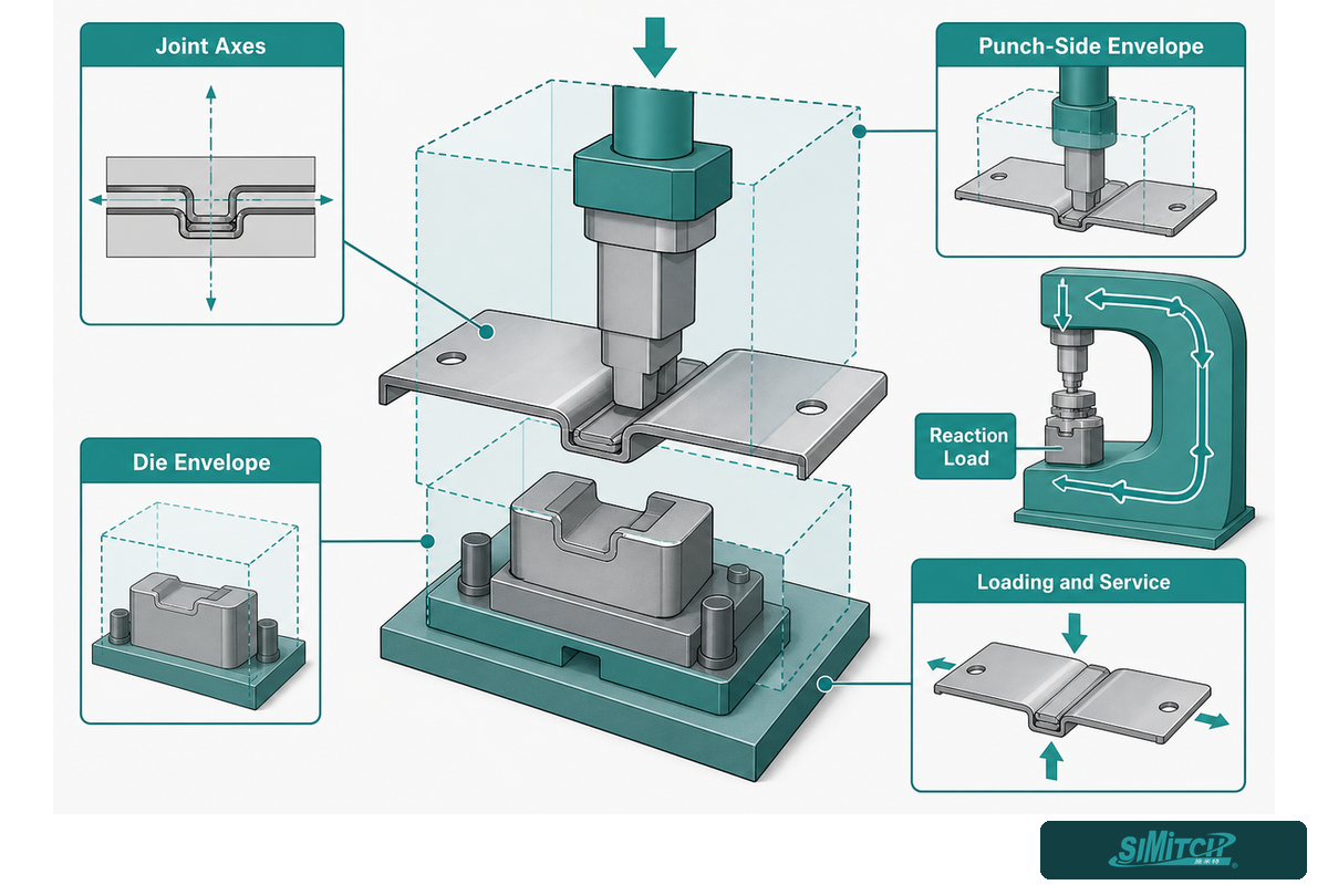
The most common SPR mistake on a screen is to draw only the visible rivet head. The process must include both the punch path and a die-side reaction path. Returns, deep draws, closed sections and nearby ribs can restrict the die, while fixtures and part-handling tools can block access even when a flat blank is easy to join.
The Die-Side Access Envelope Map
- Mark all joint axes. Indicate the approach direction and the surface that’s expected to support the formed button.
- Draw the die envelope. Reserve space for the die body, holder, reaction structure and tool-change movement, not only the contact face.
- Draw the punch-side envelope. Include the nose, clamp, rivet feed path and collision clearance.
- Trace the reaction load. Illustrate how the gun, C-frame, fixture and part resist load without unacceptable opening or deflection.
- Simulate loading and service. Even a tool that reaches an empty fixture may become inaccessible with a full part, grippers, guards or adjacent completed joints.
The map of constraints depicts application-specific equipment limits, not a universal ranking. A portable rivet gun may reach a large assembly, but it also places reaction and handling demands on the operator or manipulator. A stationary C-frame may provide a clear load path, but would require the part to move. A robotic riveting system may take the tool to multiple locations, but would require resolution of payload, hose and rivet feed routing, collision clearance and frame stiffness. These constraints are application specific, and not a general ranking.
Key takeaway
Complete the access envelope on the real part before choosing a gun, C-frame or robot. A feasible material stack is not a feasible production joint until both tools and their reaction path fit.
Build a Controlled SPR Trial
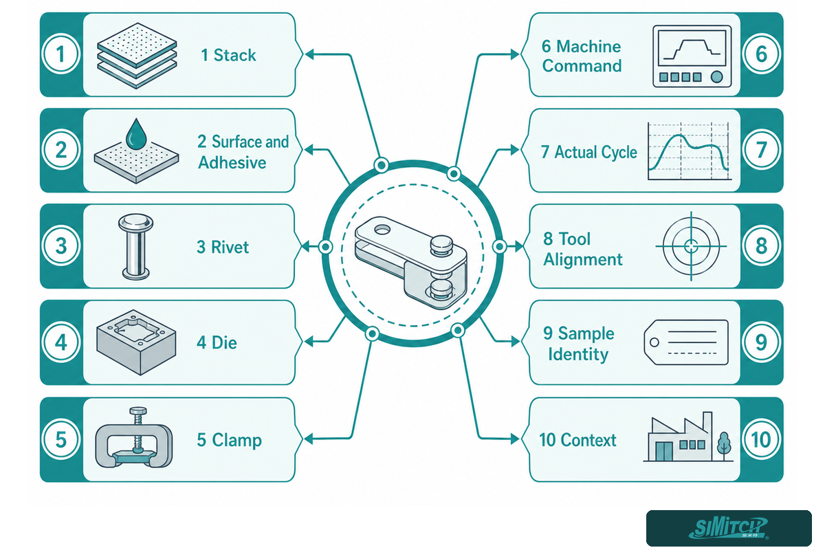
It’s important to understand cause and effect. If the team changes the rivet, die, stack order and clamp and drive settings simultaneously, a successful sample has no portable explanation and a failed sample has no clean diagnosis.
The 10-Variable SPR Trial Card
The following card is an example of an engineering record, not a general standard or a replacement for the project test plan. Alter the level of detail in the record to the assembly and the level of risk.
| # | Variable family | Minimum useful record |
|---|---|---|
| 1 | Stack | Material, grade, temper, thickness, tolerance and layer order |
| 2 | Surface and adhesive | Coating, lubricant, cleanliness, adhesive identity and cure state |
| 3 | Rivet | Controlled identifier, geometry, length, hardness/specification and lot |
| 4 | Die | Controlled identifier, cavity/profile, condition and orientation |
| 5 | Clamp | Blankholder or clamp arrangement and commanded condition |
| 6 | Machine command | Recipe, stroke/position, speed profile, cutoff and dwell where applicable |
| 7 | Actual cycle | Force-displacement trace and relevant measured features |
| 8 | Tool alignment | Punch/die condition, concentricity check and fixture state |
| 9 | Sample identity | Part/coupon ID, joint position, orientation and section plane |
| 10 | Context | Material lot, environment, operator/setup state and any deviation |
Start with a rivet-die combination selected for the stack and repeat samples in controlled locations. Explore the process window by holding all other factors constant, sample and test the resulting process while changing one of the constrained factors. In the case of adhesives, the trial plan should state whether the joint will be evaluated before or after cure, and what’s considered production conditions in terms of squeeze-out or gap.
Wrong-tool prevention deserves explicit ownership. A patent may show one architecture that compares actual die movement to an expected value, but a published patent isn’t proof that every SPR machine has that functionality. The release plan should explain how rivet identity, die identity, setup and recipe are checked in the chosen system.
Key takeaway
A good trial is traceable enough to explain the result. Keep the stack, rivet, die, machine condition, sample position, signal and physical evidence under one identity.
Use a Four-Layer Joint Proof Ladder
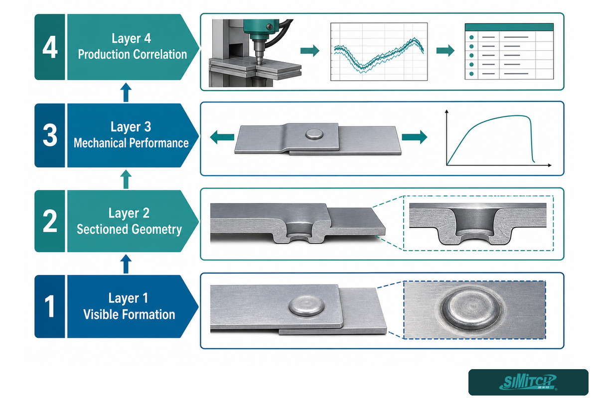
No single inspection proves everything about an SPR joint. A useful control plan builds evidence in layers, with each layer addressing a different question.
- Layer 1: visible formation. Check seating of rivet heads, surface damage, cracks, die-side button position and the completeness of the button. This may quickly address formation problems that are apparent, but the internal interlock cannot be assessed by appearance.
- Layer 2: sectioned geometry. Measure agreed features such as head position, flare or interlock, and minimum remaining bottom-sheet thickness. Give the position of the section plane and location of the sample. An off-centered or angled cut can distort the apparent interlock, so the method should adhere to discipline of preparation.
- Layer 3: mechanical performance. Use the test modes and the orientation of the specimen(s) dictated by the application. Tensile shear, cross tension, peel, fatigue and functional assembly are not equivalent. Record the failure mode and the response of the specimen, including the load and the physical failure.
- Layer 4: production correlation. Connect accepted physical joints to material lots, tool life, settings and cycle signals. Define sampling, reaction and revalidation. Add environmental ageing or cyclic duty when the service risk requires it; initial static coupons do not prove lifetime performance.
ISO 12996:2013 provides specimen-geometry and tensile-shear test-procedure scope for single mechanical joints, including single- and multi-layer specimens within the standard’s stated limits. Its public abstract refers to a maximum individual sheet thickness of 4.5 mm. That is a test-standard scope statement, not an SPR machine capacity, a process qualification or a universal acceptance threshold. Use the purchased standard and the project specification when its procedure applies.
Why interlock alone is not enough
While the interlock is important, it can’t represent the complexity of all of the elements that influence load transfer. There are studies that compare measurements of joint sections. These studies show that joints can exhibit vastly different cross-tension behavior, even when the interlock is similar, due to the shape of the flare and the amount of retained material. Use the geometry of the sample and the required physical test to confirm the specified performance.
Key takeaway
Appearance, section geometry, mechanical testing and production correlation are complementary. Do not promote one convenient measurement into a complete joint approval.
What Force-Displacement Monitoring Can and Cannot Prove
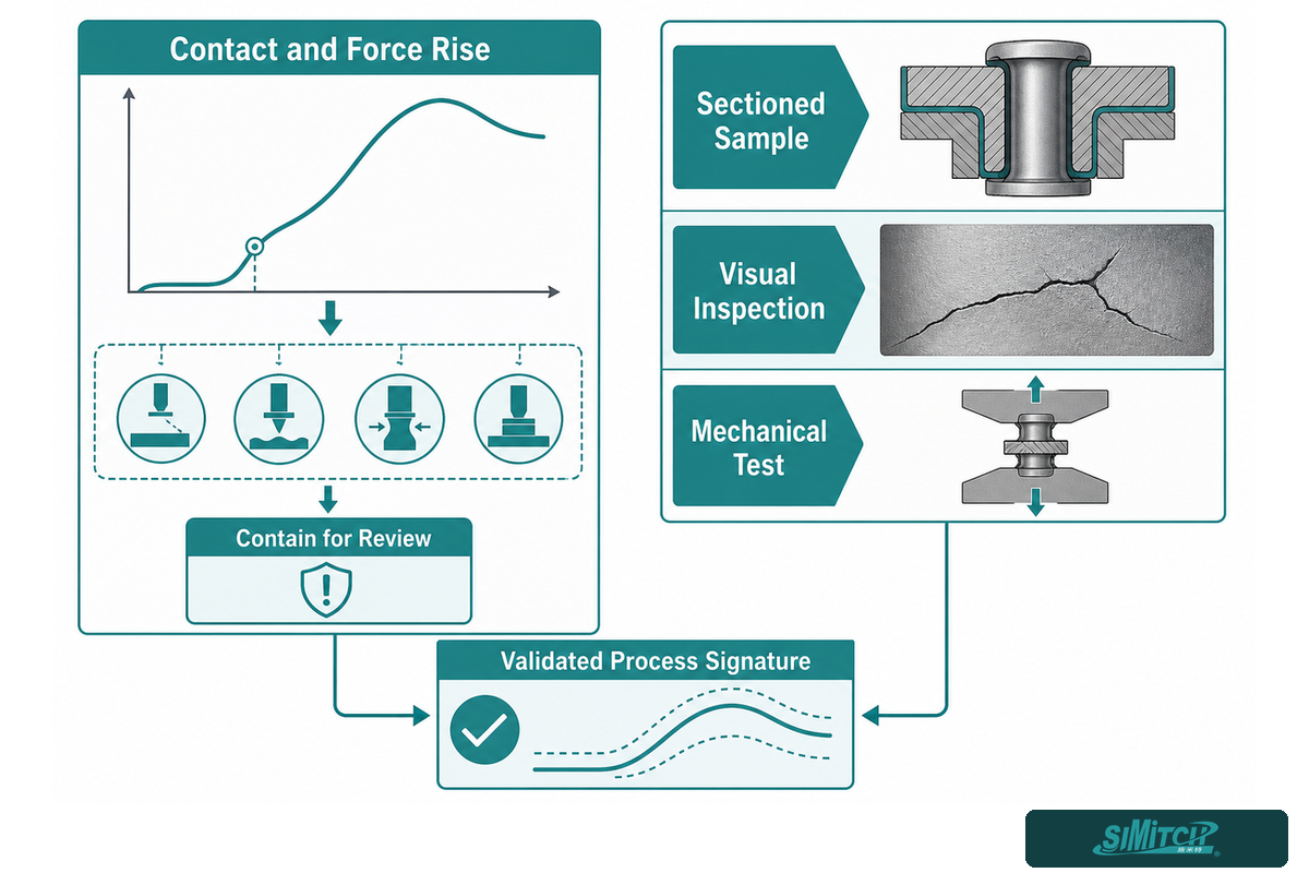
The force-displacement curve captures the response of the machine and the stack during the setting cycle. There may be features of interest such as contact position, force rise, displacement at a selected force, peak force and final position. Once features of interest have been correlated with approved physical joints, the tolerance band can be used to determine the presence of drift, feed errors, different stack or tool conditions.
TWI’s SPR monitoring guidance defines benchmarking force against punch displacement and constructing an experimental tolerance band. This document advises that monitor signals may not align with joint properties. This is where the line must be drawn. The trace is a process signal, and the meaning can be interpreted only by tested joints.
A peer-reviewed monitoring study adds weight to the boundary. The conventional force-displacement method was insensitive to several visible conditions, including lateral rivet offset, sheet cracking, button cracking and button loss. Therefore, a defect can exist in the physical sense, while a cycle may lie within a defined numerical range.
| Monitoring can help answer | Monitoring cannot answer by itself | Corroborating evidence |
|---|---|---|
| Did this cycle resemble the validated process signature? | Is the internal interlock acceptable? | Sectioned sample |
| Did contact, force rise or final position drift? | Is there a crack or off-axis rivet? | Visual and dimensional inspection |
| Should the joint or part be contained for review? | Does the joint meet the required load case? | Mechanical or functional test |
| Has a process input changed enough to trigger investigation? | What the root cause is | Tool, material, fixture and sample diagnosis |
Construct the monitoring window by using accepted and challenged samples made under controlled conditions. Specify which signal characteristics trigger an alarm, whether the alarm stops or quarantines production, who reviews it, and what data justifies resuming production. Revalidate after making a significant change. A broad band that never sounds an alarm isn’t control; a narrow band that rejects normal variation of the material isn’t control either.
Key takeaway
Use the force-displacement trace to screen a validated process. Keep visual inspection, sectioning and mechanical evidence where the control plan requires them.
Separate Formation Defects From Load-Test Failures
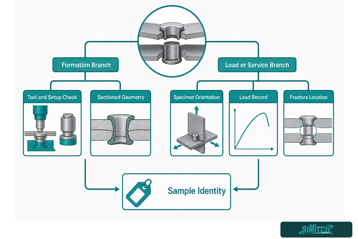
A weak joint and a badly formed joint can look similar, but they are different diagnoses that may overlap. Combining the two makes teams head toward fixing the wrong issue. To determine what happened, ask whether the fault occurred while forming the joint or while the completed joint carried a test or service load.
The Formation-vs-Load Failure Split
Formation branch
- Empty or repeated riveting
- Rivet flip, offset or off-axis entry
- Under-driven or over-driven head
- Inadequate flare or malformed button
- Upper- or lower-sheet cracking
- Wrong rivet, die, stack or alignment
First evidence: sample identity, appearance, trace, tool/setup check and sectioned geometry.
Load or service branch
- Rivet pull-out or pull-through
- Sheet tearing or bearing failure
- Interfacial separation
- Peel-sensitive failure
- Fatigue crack initiation
- Corrosion-related degradation
First evidence: load case, specimen orientation, load-displacement record, fracture location and service context.
Keep the failed specimen. Don’t grind through the only fracture surface before recording the failure path. Note its material lot, rivet, die, machine cycle and position. Then section and inspect representative adjacent joints. Repeat the test after one bounded setup change. Don’t treat more setting force as a generic fix; it can alter piercing, flare, sheet thinning and crack risk together.
When a load test fails, document how it failed. A peak load without a failure mode hides the mechanism and makes comparisons unreliable. Rivet pull-out, sheet tearing and rivet fracture don’t support the same conclusion, even when their peak values are close. Where cyclic loads or a corrosive service environment are relevant, extend the proof plan instead of treating a static tensile-shear coupon as lifetime evidence.
Key takeaway
Diagnose formation from forming evidence and load failure from the tested load path. Preserve traceability between the physical joint, its cycle and its test result.
Guarding and Change Control Belong in the Process Plan
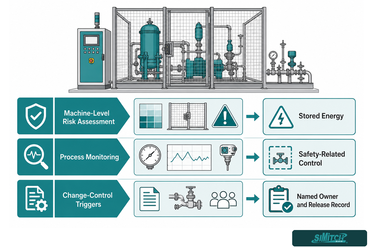
SPR systems combine high-force machine-level actuation with moving tools, stored energy, rivet feeding, and manual or automated handling in one machine-level risk assessment. Process monitoring and safety-related control are two distinct functions. While a curve alarm might help contain suspect joints, it isn’t automatically a safety function.
Regarding a narrow U.S. federal scope point, 29 CFR Part 1910 Subpart O places riveting machines outside the mechanical-power-press requirements of 1910.217(a)(5). This exclusion doesn’t mean an unguarded riveting machine is allowed. An OSHA interpretation specific to riveting machines refers to the general safeguarding requirement of 1910.212(a)(1). This is a scope note, not legal advice or a complete assessment for a machine, task, installation or jurisdiction.
Change-control triggers
Define which revisions require review, sample checks or full revalidation before release. The list typically includes changes to sheet grade, temper, thickness, supplier or coating; adhesive type or cure state; layer order; rivet or die revision; tool maintenance; punch/die alignment; feeder changes; sensor replacement or calibration; force, speed, stroke or tolerance-band settings; software; fixture; guard; loading mode; and production location.
A practical release question
If this change affects moving material, access to joints, the path of reaction, measurement of cycles, exposure of operators, or the meaning of the existing acceptance criteria, it should be reviewed by the named owner and revalidated before the process is used.
Key takeaway
Guarding is a machine responsibility, and a process change can invalidate both joint evidence and safety assumptions. Give each review a named owner and release record.
Translate Joint Proof Into Equipment Requirements, Then Revalidate
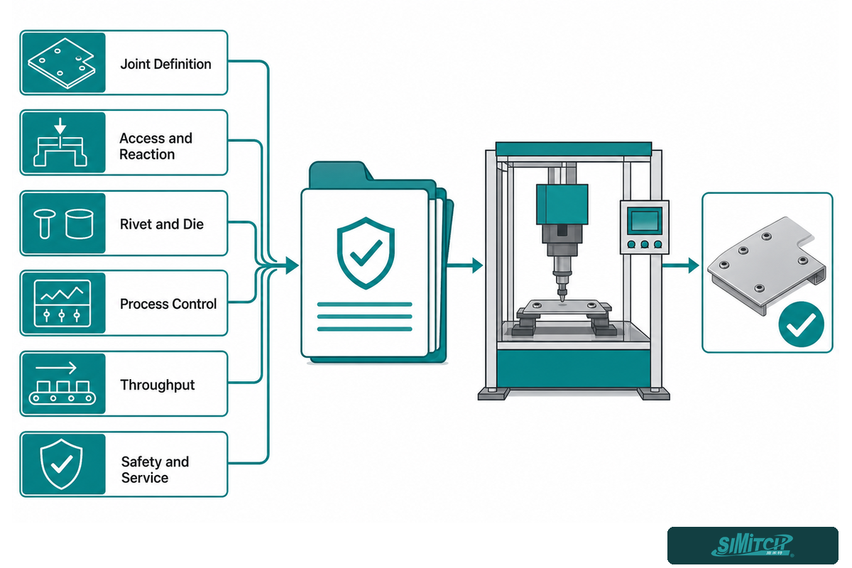
Once a credible joint window is demonstrated during feasibility trials, use this evidence to define the machine requirements. This isn’t a one-way process. The target machine’s stiffness, tooling, clamping, force-motion profile, sensing, and access can affect joint formation, so the final process requires its own confirmation.
Current research studies have outlined the relationship between punch velocity and coupled phenomena such as SPR formation, joining force, geometric parameters and joint characteristics. The purchasing lesson is not to assume that coupons made on a given laboratory or trial press will hold for other drive systems or motion profiles. The result of a trial should be converted into a requirement and confirmation coupons should be made in the proposed production configuration.
| Requirement | Evidence sent to the supplier | Production confirmation |
|---|---|---|
| Joint definition | Stack, drawings, positions, surfaces and acceptance duty | Samples use controlled production materials |
| Access and reaction | 3D envelope, approach, flange/return geometry and fixture concept | All joints remain reachable with guards and handling present |
| Rivet and die | Controlled candidate IDs and trial sections | Tool identity, condition and changeover are error-proofed |
| Process control | Required settings, signals, records, alarms and traceability | Target-machine curves correlate with accepted physical joints |
| Throughput | Production rate, handling, changeover and containment assumptions | Measured good-joint output includes rejects and interruptions |
| Safety and service | Operating modes, interventions, utilities, maintenance and risk responsibilities | Selected safety functions and maintenance tasks are validated |
Mobile or handheld systems can be used for large assemblies or distributed joints. Stationary systems can be used for parts that can be easily brought to a fixed load frame. Robotic systems can support repeated multi-position work and integrated records. None can be considered the “best” without the part, access, output requirements, control strategy and service capabilities.
Once those inputs are available, evaluate them along with the configurations of SIMITCH’s self-piercing riveting machines. Models, published specifications, commercial offers and quotes will be found on that solution page; this guide will remain for the preparation of the engineering tasks.
Key takeaway
Let the joint evidence write the equipment requirement, then prove that the target machine, tooling and motion profile reproduce the accepted joint and its control signals.
Frequently Asked Questions
Do self-piercing rivets require a predrilled hole?
Normally not in conventional semi-tubular SPR.
The rivet normally pierces the upper layer or layers and flares in the die-supported bottom layer. That bottom layer should retain material for the mechanical interlock. Specialized pre-hole variants exist for some difficult stacks, so the no-hole statement should not be applied to every research process carrying an SPR label. The distinction also affects the trial record: a special pre-hole route adds hole geometry, location and preparation as controlled inputs. In every case, qualify the exact stack, rivet, die, process variant and access arrangement rather than assuming the process name settles feasibility. Record the version on drawings and work instructions so a later team does not apply conventional-SPR evidence to a materially different joint.
Can SPR join aluminum to high-strength steel?
Some ordered aluminum and high-strength steel stacks can be joined, but the material pair alone is not approval; grade, thickness, order, tooling, and test evidence still control feasibility.
Grade, temper, thickness, layer order, coating, adhesive, rivet hardness and geometry, die shape and setting profile all affect formation. Lower-sheet behavior is particularly important because the rivet must flare without unacceptable cracking or breakthrough. Run controlled samples, inspect section geometry, and perform the application’s required mechanical tests before releasing the stack or choosing production equipment.
Are SPR joints as strong as spot welds?
There is no universal winner across stacks and load cases; compare SPR and spot-welded specimens under the same material, geometry, loading, corrosion, and service-life requirements.
A result changes with material stack, joint spacing, adhesive, load direction, specimen geometry, corrosion exposure and test method. Tensile shear, cross tension, peel and fatigue do not answer the same question. Compare qualified specimens or assemblies under the load cases that matter to the product. Keep process capability separate from claims about the finished joint.
What can force-displacement monitoring detect?
It can flag departure from a validated cycle signature.
It may expose changes in contact, force rise or final position. It cannot certify interlock, cracks or joint strength, so retain physical checks in the control plan.
What should I send to an SPR equipment supplier?
Send the controlled joint and process requirement, including stack order, drawings, access, production rate, traceability, and acceptance evidence, rather than only requesting a machine force.
Include drawings or 3D data, every layer’s material and thickness, stack order, coatings and adhesive, joint locations, die-side access, surface-marking limits, production rate, loading method, traceability, utilities, integration interfaces and the acceptance evidence expected from trials. Identify which samples are representative of production and how final equipment revalidation will be judged.
Prove the Joint Before You Freeze the Machine
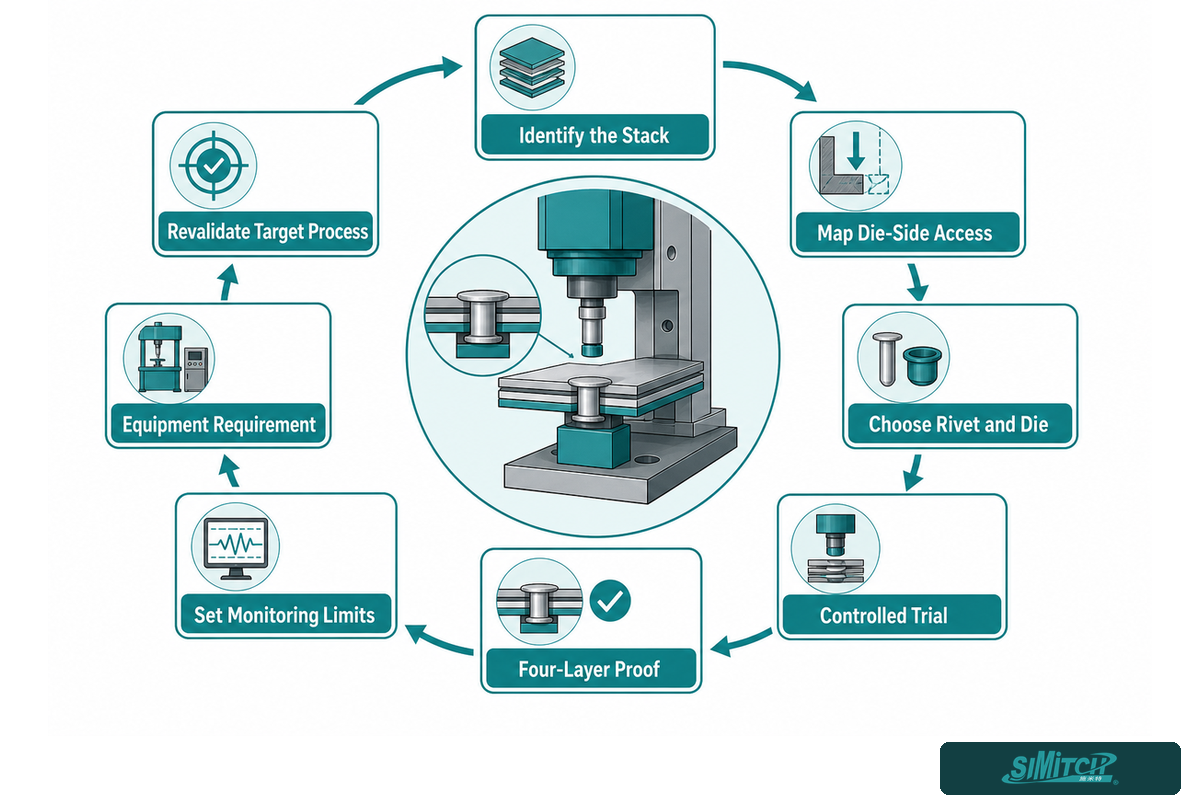
A useful SPR approach is a closed engineering loop: identify the stack, map die-side access, choose candidate rivets and dies, conduct a controlled trial, build the four-layer proof, set monitoring limits, diagnose failures by mechanism and translate the result into a production requirement. Then repeat the critical proof on the target process.
This sequence keeps commercial selection in its proper place. It also makes supplier discussions more efficient because unresolved joint risks are visible before anyone commits to a model, cycle time or automation package.
Suzhou Simitch Machinery Co., Ltd. introduces its company and manufacturing focus on the About SIMITCH page. For the broader company and equipment overview, visit the SIMITCH homepage. First-party information on company experience and capability statements is provided unless verified otherwise.
Prepare the stack and joint drawing
When reviewing the application, provide the material order, joint locations, access envelope, and required evidence.
References & Sources
- Investigation into the Effect of Interlock Volume on SPR Strength, peer-reviewed article.
- Intelligent monitoring of self-piercing riveting based on image processing and deep learning, peer-reviewed article.
- Self-Pierce Riveting: Development and Assessment for Joining Polymer-Metal Hybrid Structures, peer-reviewed review.
- TWI: monitoring the self-piercing riveting process.
- ISO 12996:2013 public scope page.
- 29 CFR Part 1910 Subpart O.
- OSHA interpretation on guarding riveting machines.
- 2025 study comparing conventional and pre-hole SPR for GFRP/steel joints.
- 2026 study of punch-velocity influence in clinching and SPR.
Editorial note: The SIMITCH content team reviewed this guide against current public technical, standards-scope and regulatory sources. Qualified engineering and safety teams remain responsible for joint acceptance and machine safety in the actual application.
![Hot-Melt Connection Molds & Equipment Guide [2026]](https://simitch.com/wp-content/uploads/2026/09/hot-melt-connection-molds-equipment-guide-featured-768x512.png)