Get in touch with Suzhou Simitch Machinery Co., Ltd Company

Aluminum joining is the controlled connection of aluminum to another layer, part, or material through thermal, mechanical, adhesive, or hybrid methods. Choose a process by identifying the actual stack first. Alloy, temper, layer order and thickness; coating; access; load direction; heat limits; service environment; inspection and repair route, all of which can disqualify a route. The process families are conditional options, not rankings.
For product-family context, see SIMITCH riveting equipment.
Updated August 2026 · By XCX
Quick Specs
| First decision input | The complete material stack and joint geometry |
| Five rejection filters | Material, geometry, access, interface/service, and production control |
| Main process families | Welding, brazing, bonding, threaded fastening, clinching, riveting, and hybrids |
| Unknown input | Unresolved evidence, never a pass |
| Published test examples | 11.57 kN lap shear and 5.65 kN cross tension in one ORNL friction-SPR configuration; not design limits |
| Release basis | Representative specimens, application-specific tests, and monitored production trials |
The fastest sound aluminum joining decision is often a rejection decision. If the stack, access, heat limit, interface protection, or monitoring plan is unknown, the process is not ready for equipment selection.
Key points
- Aluminum grade alone isn’t a process specification; temper, thickness, coating, geometry, and layer order also matter.
- A method that leads in one static test can behave differently in peel, fatigue, corrosion, or mixed loading.
- Aluminum-to-steel joining adds metallurgical, coating, isolation, and galvanic questions that same-alloy joints may not have.
- Self-piercing riveting is a configuration, not merely a machine choice: rivet, die, stack, material state, and acceptance evidence travel together.
- A useful quote request states required performance and physical constraints before it prescribes a machine design.
Aluminum Joining Starts With the Stack, Not the Process Name
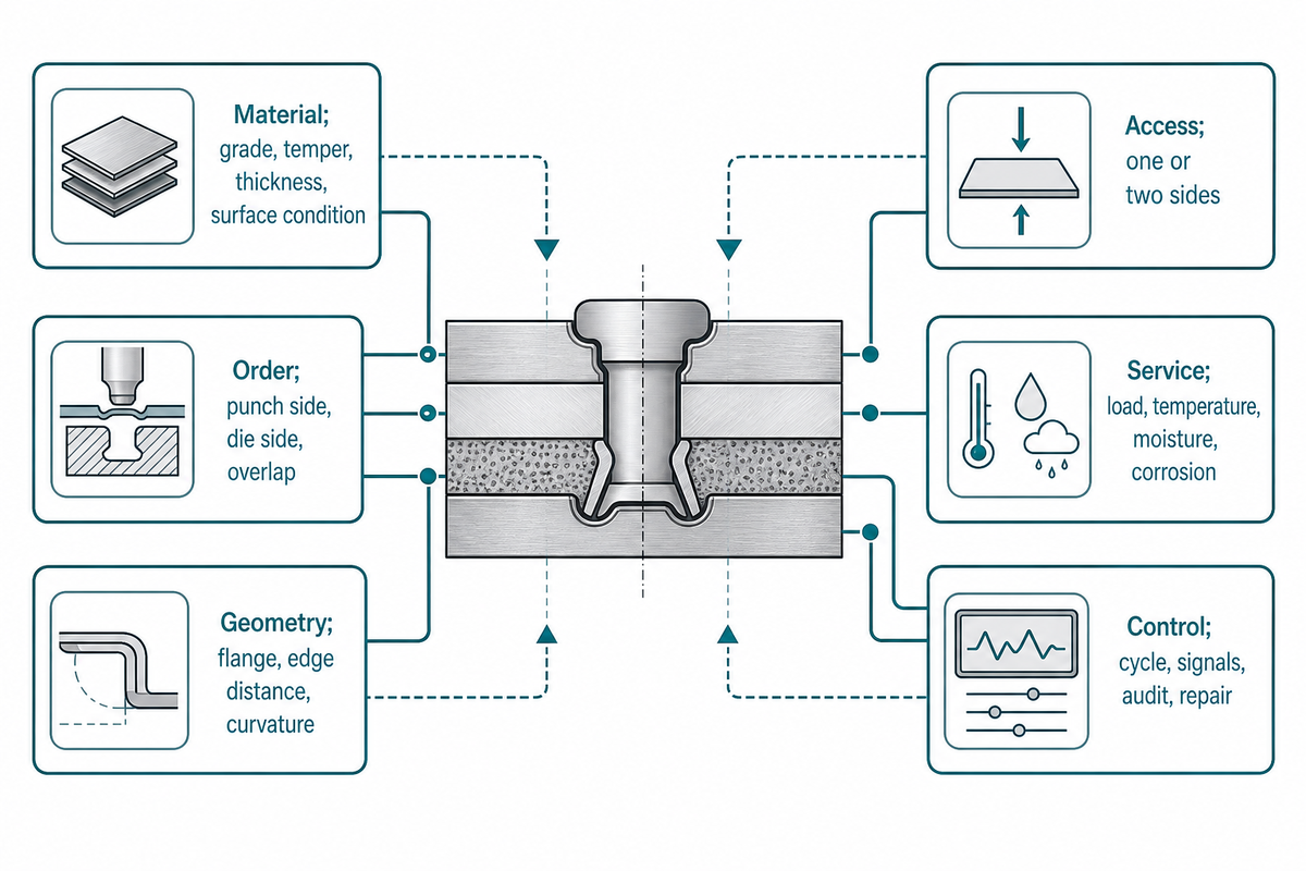
Identify a one-line stack definition: alloy and temper for every layer, layer order, thickness, coating or treatment, joint shape, accessible sides, load direction, thermal limit, service exposure and inspection route. Mark every blank field as unknown before comparing process families and their qualification frameworks. That same quote request starts with this stack record.
“Aluminum” covers castings, work-hardened sheet, formed plate, and extrusions with widely different formability. A sheet-forming route needs enough ductility in the material state actually supplied. A fusion route must account for oxide, filler choice, heat flow, distortion, and the selected welding process. Bonding must include surface treatment, bond-line control, cure history, and environmental durability.
Stack Definition Card
Material: grade, temper, thickness, surface condition · Order: punch side, die side, overlap · Geometry: flange, edge distance, curvature · Access: one or two sides · Service: load, temperature, moisture, corrosion · Control: cycle, signals, audit, repair.
The required evidence also changes with the surviving family. ISO 15614-2:2025 names specific arc-welding processes for aluminum and its alloys; it is not a release standard for adhesive bonding, clinching, or self-piercing riveting. The process determines which qualification framework applies, while the product and customer requirements determine the acceptance criteria.
What information is needed to choose an aluminum joining process?
Note the alloy and temper of every layer, not just aluminum. Add layer order and thickness, coating, adhesive or sealant, flange width, overlap, edge distance, curvature, and tool access. Define loads by direction and service history rather than one target force.
List any heat input, visible marking, distortion, contamination, water ingress, galvanic corrosion, or later repair that would disqualify a route. Name the inspection method and production signal indicating drift. Without this minimum boundary, a supplier can only establish a different configuration.
Evidence capsule: The American Welding Society’s 2025 aluminum guidance distinguishes choices by process, thickness, filler, polarity, and oxide condition. That supports a stack-first screen, but it doesn’t turn one welding setup into a universal window for every aluminum product.
Run the Five-Rejection Aluminum Joint Screen
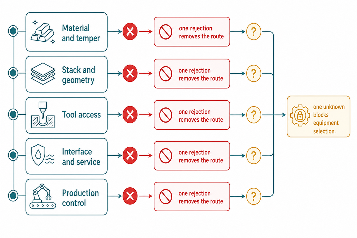
Reject a route when it can’t clear material behavior, stack geometry, tool access, interface and service exposure, or production control. Mark missing evidence as unknown rather than green. This screen is an editorial synthesis of public technical evidence; it isn’t a substitute for application-specific design review or physical trials.
Five-Rejection Aluminum Joint Screen: 5-Filter Rejection Matrix
A 5-filter rule: one rejection removes the route; one unknown blocks equipment selection until evidence closes it.
| Filter | Pass evidence | Reject signal | Unknown means |
|---|---|---|---|
| Material and temper | Representative state forms, melts, or bonds as required | Cracking, excessive softening, or unstable interface | Get material certificates and specimens |
| Stack and geometry | Order, thickness, overlap, edge, and support fit the process | No room for interlock, fusion zone, fastener, or bond line | Freeze drawings and tolerances |
| Tool access | Tool, electrodes, die, or clamp reach every joint | Frame, return flange, or assembly sequence blocks access | Run a digital and physical reach study |
| Interface and service | Surface, seal, cure, heat, moisture, and corrosion plan are compatible | Coating damage, galvanic path, or unqualified aging condition | Define service spectrum and protection |
| Production control | Cycle, monitoring, traceability, audit, and repair are feasible | No observable signal or no response to a failed audit | Design the control plan before release |
A red result saves a trial on an unsuitable family; an unknown is equally useful for planning the next engineering task. For example, high strength aluminum with low elongation doesn’t automatically reject every mechanical option; published work on high strength aluminum shows that processing, local behavior, rivet and die conditions must be evaluated together. The correct action is a representative trial, not a guessed green cell.
Evidence capsule: An Oak Ridge National Laboratory study on one AA7055-T76 friction self-piercing configuration reported about 11.57 kN lap-shear strength and 5.65 kN cross-tension strength. Those values are configuration-specific; their real lesson is that die design changed interlock, failure mode, and strength.
Compare Welding, Brazing, Bonding, Clinching, and Riveting by Constraint
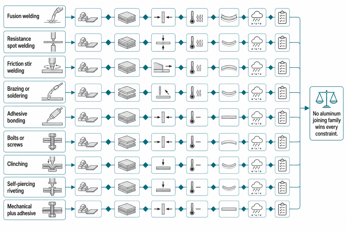
No aluminum joining family wins every constraint. Fusion routes create a metallurgical joint but add heat and process-specific surface control. Adhesives distribute load but depend on preparation and cure. Mechanical routes limit bulk heating but need geometry, access, deformation, or consumables. Compare each family against one stack and evidence plan. This carries the prior stack definition forward.
| Route | Typical joint | Heat | Access | Key dependency | Evidence needed | Common reject |
|---|---|---|---|---|---|---|
| Fusion welding | Butt, lap, fillet | Base metal melts | Often one side | Oxide, filler, shielding, heat flow | Procedure, macrosection, mechanical tests, distortion | Heat or distortion limit |
| Resistance spot welding | Sheet overlap | Localized fusion | Two-sided electrodes | Current path, contact, electrode condition | Nugget and process-signal plan | Blocked access or unstable interface |
| Friction stir welding | Linear seam | Solid-state heating | Tool side plus backing | Clamping, path, tool, backing | Section, defects, load, path control | No backing or poor path access |
| Brazing or soldering | Seam or fitted joint | Filler melts | Heat and filler access | Gap, filler, flux, cleanliness | Fill, section, corrosion, service temperature | Gap or thermal mismatch |
| Adhesive bonding | Overlap or flange | Cure-dependent | Application and clamp access | Surface, bond line, cure | Preparation, aging, peel and shear | Uncontrolled surface or cure |
| Bolts or screws | Detachable overlap | No joining heat | Tool side; nut may need reverse | Hole, bearing, preload, isolation | Torque/preload, fatigue, loosening | No hole allowance or poor access |
| Clinching | Thin-sheet overlap | No bulk melting | Punch and die | Local formability and die geometry | Neck, interlock, cracks, loads | Insufficient deformation window |
| Self-piercing riveting | Thin-sheet overlap | No bulk melting in conventional SPR | Setter and die | Rivet, die, stack, material state | Head, interlock, residual bottom, cracks | Poor die-side integrity or reach |
| Mechanical plus adhesive | Hybrid overlap | Cure-dependent | Both process access needs | Sequence, squeeze-out, load sharing | Combined process and aging evidence | Unqualified interaction |
The table is a routing tool, not a scorecard. For a broader classification before this constraint screen, review these metal joining methods. The prior ORNL configuration is one bounded example. A 2000 SAE comparison separated static, T-peel, and fatigue behavior for self-pierced, resistance-welded, and hybrid joints made from steel and aluminum sheets. That study matters because it shows why one test can’t establish a universal winner. The load mode and joint configuration stay attached to the result.
Terminology boundary
United States production teams usually write aluminum; many British sources write aluminium. Buyer searches phrase the topic as “aluminum joining process,” “aluminum joining methods,” “joining aluminum without welding,” “joining aluminium without welding,” or “aluminum brazing rod.” Search results may also mix an industrial workpiece with a TIG welder, brazing rods, copper backing, a torch or propane torch, glue, hardware, or a bracket repair. Those terms don’t define structural applications. Material thickness, fit-up, oxide layer, filler metal, a malleable state, operator access, and the way a clamp must compress the stack are still separate inputs. “Strong bond” isn’t an acceptance criterion, and that limitation applies even when a demonstration looks clean.
Which aluminum joining methods avoid melting the base metal?
Bolts, screws, conventional riveting, self-piercing riveting, clinching, and adhesive bonding can join aluminum without melting the base sheet. Friction stir welding is also a solid-state process, although frictional heat and plastic flow are central to the joint. Brazing and soldering melt a filler while keeping the base material below its melting point.
Conventional self-piercing riveting should be kept separate from friction self-piercing riveting, which deliberately adds rotation and heat. “No bulk melting” doesn’t mean no material change: mechanical routes deform the stack, adhesives cure and age, and solid-state routes still create heat and microstructural effects. Each route therefore needs its own evidence.
Evidence capsule: SAE 2000-01-2681 studied sheets in the 1–2 mm class and evaluated static, T-peel, and fatigue behavior separately. The bounded study supports multi-mode comparison, not a universal method ranking or an uncited strength threshold.
What Changes When Aluminum Must Join Steel?
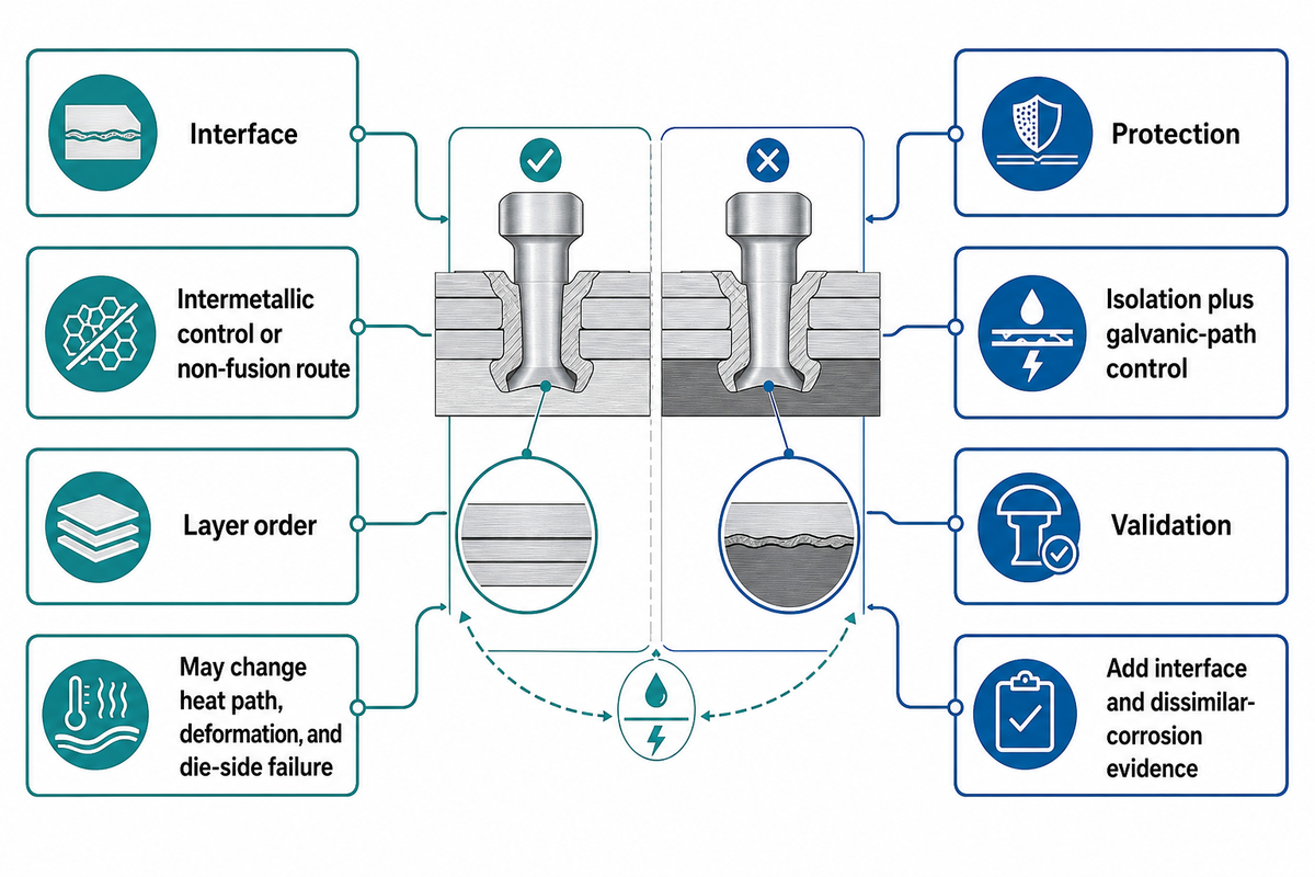
An aluminum-to-steel joint adds material compatibility, layer direction, coating damage, electrical isolation, moisture paths, and galvanic corrosion to the normal geometry and access questions. “Aluminum to steel” isn’t a complete process setting. The exact grades, coatings, interface, section geometry, and service environment must remain attached to every claim. That method comparison becomes more demanding when one layer is steel.
Direct fusion can form brittle intermetallic layers and faces different melting and heat-flow behavior in the two materials. That doesn’t justify saying aluminum and steel can never be welded. Specialized resistance-derived, friction-based, transition-material, insert, mechanical, and hybrid routes exist, but each solves a bounded stack under controlled conditions. A NIST report on aluminum-steel galvanic exposure also shows why coating damage and environmental protection belong in the evidence plan.
| Question | Same-alloy stack | Aluminum-to-steel stack |
|---|---|---|
| Interface | Oxide and local material state | Intermetallic control or non-fusion route |
| Layer order | Still process-dependent | May change heat path, deformation, and die-side failure |
| Protection | Seal and coating continuity | Isolation plus galvanic-path control |
| Validation | Mechanical and environmental plan | Add interface and dissimilar-corrosion evidence |
A useful contradiction comes from SAE 2007-01-1703: coated mild steel was spot-friction welded to 6000-series aluminum using a particular tool and schedule. The study used a 10 mm shoulder, rotation between 1,500 and 2,000 rpm, and a 5-second joining time. Those numbers prove a specialized route existed in that experiment; they aren’t transferable production settings.
When Does Self-Piercing Riveting Fit an Aluminum Sheet Stack?
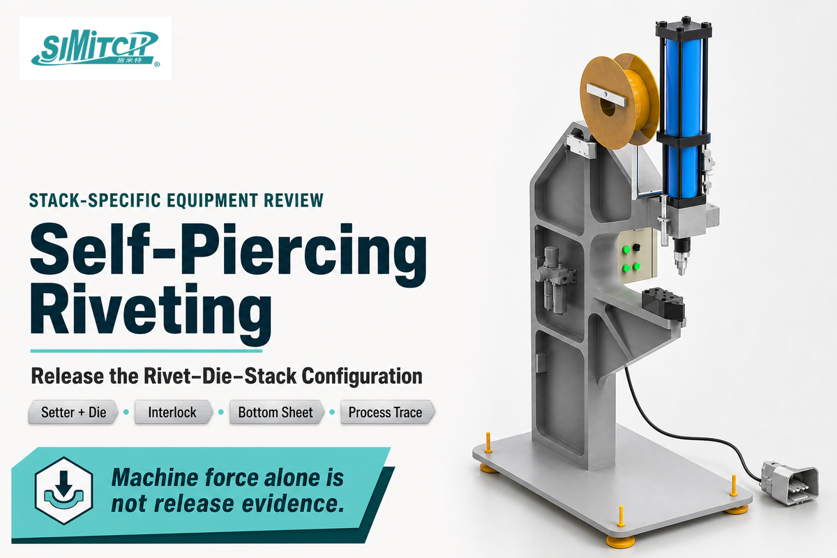
Consider conventional self-piercing riveting where an automatable point joint, no predrilled hole, and no bulk melting fit the assembly. The stack must allow setter-and-die access, local deformation, rivet flaring, sufficient interlock, and an intact die-side sheet. Rivet, die, material state, layer order, and acceptance evidence comprise a configuration. That comparison stays stack-specific.
The rivet pierces the upper layers and flares into the lower layer without fully perforating the bottom sheet. So a sectioned joint appears as a geometry: head seating, interlock, remnant bottom thickness, local necking, and cracks. Head position alone will not verify the concealed interface. The force-displacement trace may support monitoring, but it must first be correlated with destructive sections and the agreed mechanical test.
SPR configuration record
Capture rivet diameter, length, hardness and geometry; die depth, diameter and profile; every sheet grade, temper, thickness and layer position; clamp and setting conditions; head position, interlock, residual bottom thickness, crack condition, process trace and test result.
An SAE study of AA5754 tried rivet diameter, length, hardness, sheet thickness, and die shape as process variables. More recent ORNL work also found die design changed the microstructure, interlock, failure mode, and measured strength of an AA7055-T76 configuration. These results make “we have joined aluminum before” an inadequate trial record.
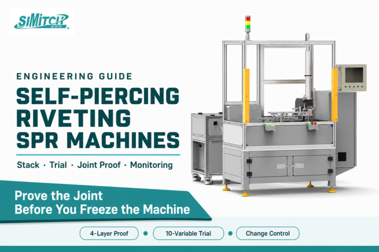
Conventional and friction self-piercing riveting should not be merged in a supplier comparison. Friction SPR adds rotation and thermomechanical effects to improve piercing behavior for difficult material states; it also creates a different process window and evidence burden. If conventional SPR survives the screen, take representative specimens and acceptance criteria to a trial, then review suitable self-piercing riveting machines only after the stack and access are fixed.
Key takeaway
SPR is not released by machine force alone; the production unit is the complete rivet–die–stack–material-state configuration and its verified joint geometry.
Evidence capsule: The ORNL AA7055-T76 study’s approximately 11.57 kN lap-shear and 5.65 kN cross-tension results belonged to one friction-SPR configuration. The portable finding is that die design and material response changed the joint, not that those values are universal acceptance limits.
How Do Adhesive and Hybrid Joints Change the Qualification Plan?
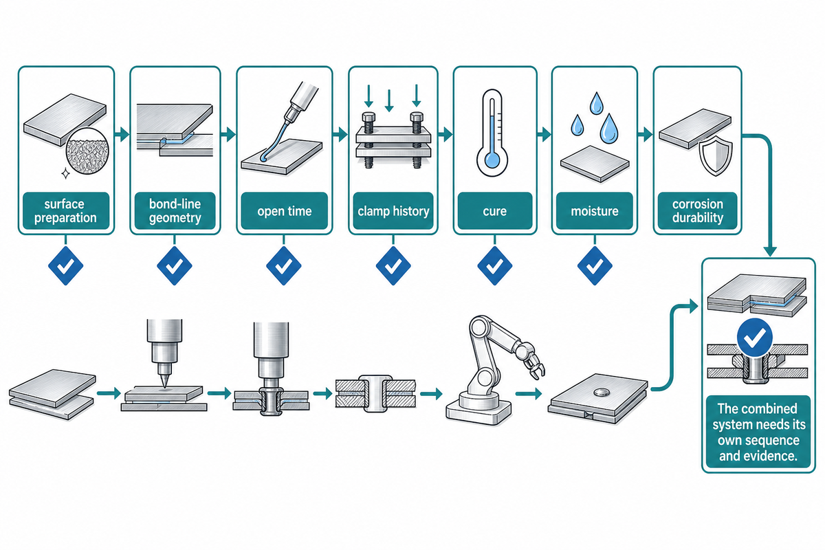
Adhesive adds surface preparation, conversion coating or primer condition, bond-line geometry, application amount, open time, clamp history, cure, moisture, temperature, and corrosion durability. Adding a mechanical point joint also modifies squeeze-out, alignment, sealing, and load sharing. The combined system needs its own sequence and evidence.
Qualification should couple the adhesive chemistry to the real surface process. ASTM D3933-98(2025) addresses preparation and testing of aluminum surfaces for structural adhesives. ASTM D3762-24 is a wedge-test method for adhesive-bonded aluminum surface durability, a separate scope. Neither standard makes one adhesive adequate for every surface, cure schedule, or service condition.
“Improper surface preparation can produce seemingly acceptable bonds.” — ASTM D3933 significance statement, shortened excerpt
A hybrid can hold parts during cure, improve sealing, or shift load behavior, but the mechanical point can also disturb the bond line. Record the order of dispense, assembly, clamping, joining, and cure. Then test aged and unaged specimens in the load modes that matter. Don’t apply an improvement percentage from one alloy, adhesive, and specimen to a different production stack.
What Evidence Releases an Aluminum Joint to Production?
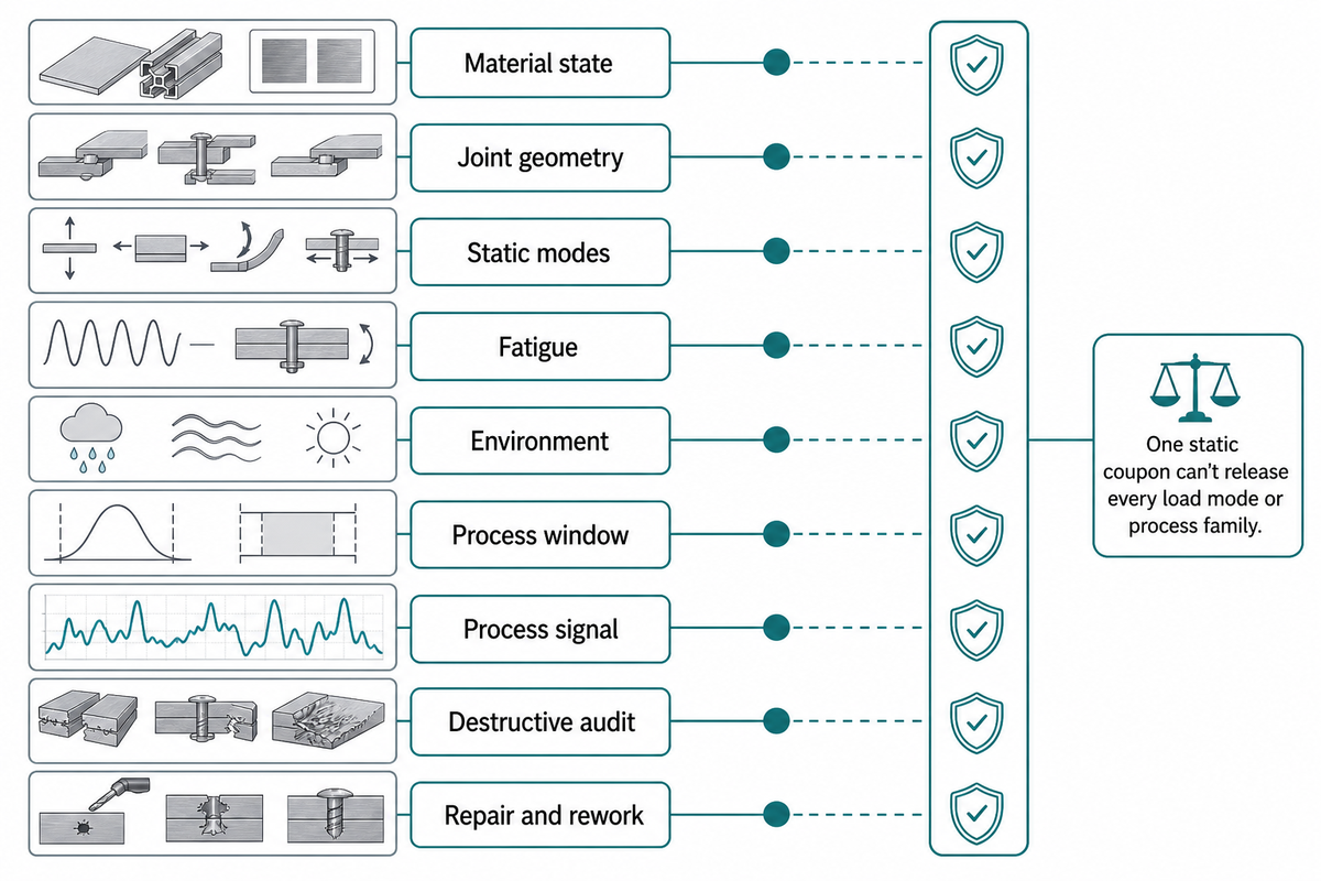
Release evidence should advance from material and joint specification through coupon work, process-window work, representative subassemblies, durability and corrosion exposure, and monitored cell work. Every stage needs an owner, a recorded input, an acceptance rule, and a response to failure. One static coupon can’t release every load mode or process family.
| Evidence item | Typical owner | Record | Release consequence |
|---|---|---|---|
| Material state | Materials / supplier quality | Grade, temper, thickness, surface, lot | Defines representative specimens |
| Joint geometry | Product engineering | Drawing, stack order, tolerances, section criteria | Freezes the tested configuration |
| Static modes | Test engineering | Shear, peel, cross-tension, or torque as relevant | Checks required load paths |
| Fatigue | Durability engineering | Spectrum, cycles, failure location | Rejects static-only assumptions |
| Environment | Materials / validation | Moisture, temperature, corrosion, aging | Confirms interface durability |
| Process window | Manufacturing engineering | Controlled factors, boundaries, sections and loads | Sets production limits |
| Process signal | Controls / quality | Force, displacement, current, torque, temperature, or path | Provides drift detection |
| Destructive audit | Plant quality | Frequency, sample, method, reaction plan | Correlates signals with joint condition |
| Repair and rework | Product and plant engineering | Approved repair, inspection, traceability | Closes the escape path |
The acceptance values belong to the application, governing specification, and customer requirements. ISO 17662:2025 supports calibration, verification, and validation planning for equipment that controls welding process variables, but its scope does not release a clinched, bonded, or riveted joint. The evidence system must follow the selected process.
Evidence capsule: SAE Technical Paper 831816, published in 1983, reports a 90-day corrosion program for steel self-piercing rivets in aluminum using a 3.5% sodium chloride solution. It supports an environmental validation stage; it doesn’t supply a universal service-life limit.
What Should Go Into an Aluminum Joining Equipment RFQ?
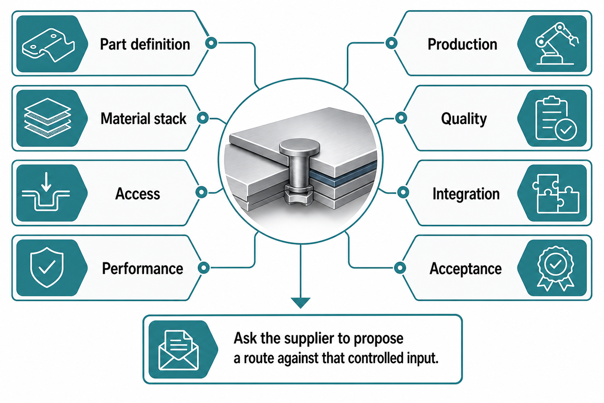
State the required function, joint performance, and essential physical constraints first. Attach drawings, stack order, material grades and tempers, thicknesses, coatings, access envelope, target load modes, acceptance method, cycle, monitoring, traceability, automation interfaces, and representative specimens. Ask the supplier to propose a route against that controlled input. That release evidence belongs in the quote request as an acceptance condition.
“Describe requirements in terms of functions to be performed.” — FAR 11.002, a United States federal procurement rule used here only as a bounded drafting principle
| Input | What to provide | Why it matters |
|---|---|---|
| Part definition | Drawings, datums, flange and tolerance data | Sets reach, support, and joint location |
| Material stack | Grades, tempers, thickness, order, coatings, lot specimens | Binds trial results to production material |
| Access | Clearance model, approach, assembly sequence | Determines tool and frame feasibility |
| Performance | Load modes, durability, environment, failure rules | Prevents a single-force specification |
| Production | Cycle, variants, uptime definition, changeover | Sizes the cell and control sequence |
| Quality | Signals, traceability, audit method, reaction plan | Makes process drift observable |
| Integration | Robot, controls, safety, data and utilities interfaces | Defines the system boundary |
| Acceptance | Specimens, trial plan, factory and site tests, documents | Turns the quote into verifiable deliverables |
Simitch states that it was established in September 2006 in Taicang, Jiangsu, and focuses on intelligent joining equipment. Its declared scope includes hydro-pneumatic boosters, precision servo-press systems, clinching, riveting, SPAC, and SPR for automotive, energy storage battery, solar photovoltaic, home appliance, and HVAC applications. This is first-party company context, not independent proof of customer outcomes or a promise for a specific stack.
Discuss Your Aluminum Joint Stack
Bring the drawing, complete stack, access envelope, target load modes, environmental conditions, cycle, and inspection plan. Simitch can review the input and define what a representative joining trial must prove.
Frequently Asked Questions
What is the best way to join two pieces of aluminum?
Answer
The best route depends on the parts, not aluminum alone. Define the alloy and temper, thickness, joint geometry, tool access, load direction, heat limit, service environment, inspection method, and production volume first. Welding, brazing, adhesive bonding, bolts, clinching, and self-piercing riveting can all be valid within different windows. Shortlist only the routes that clear those constraints, then confirm the chosen configuration with representative material and application-specific tests.
How can aluminum be joined without welding?
Answer
Non-weld options include bolts and screws, conventional riveting, self-piercing riveting, clinching, and adhesive bonding. Mechanical routes differ in access, holes or consumables, visible joint features, and the material deformation they require. Adhesives add surface preparation, cure, and environmental durability requirements. A hybrid joint can combine adhesive with a mechanical point joint, but the combined stack, process sequence, and inspection plan still need separate validation.
What are the common aluminum joining methods?
Answer
Common families include fusion and resistance welding, friction stir welding, brazing, soldering, adhesive bonding, threaded fasteners, riveting, self-piercing riveting, and clinching. That list is a classification, not a recommendation. The practical choice depends on alloy condition, stack order and thickness, access, heat and distortion limits, corrosion protection, required joint behavior, cycle time, monitoring, and how the finished assembly will be inspected or repaired.
Can aluminum and steel be welded directly?
Answer
Some direct fusion routes face brittle intermetallic formation, different melting behavior, and difficult heat control, so a conventional steel-welding schedule may fail. That is not an absolute ban. Published specialized approaches include resistance-derived and friction-based methods, transition materials, inserts, and solid-state routes. Mechanical or adhesive-hybrid joining can avoid direct fusion but adds deformation, surface, sealing, and corrosion questions. Specify both material grades, coatings, layer order, section geometry, and service environment before selecting the route, then qualify the exact configuration.
When should an engineer choose self-piercing riveting for aluminum?
Answer
Consider it for an automatable point joint when the assembly permits setter-and-die access and the material can form the required interlock without unacceptable bottom-sheet damage. Qualify the exact rivet, die, sheet grades, tempers, thicknesses, layer order, joint geometry, and process trace together.
What must be tested before production release?
Answer
Verify joint geometry, relevant static load modes, fatigue where required, corrosion and environmental durability, process signals, destructive audit, and repair evidence. Acceptance values remain specific to the application, governing standard, and customer specification.
Research Transparency
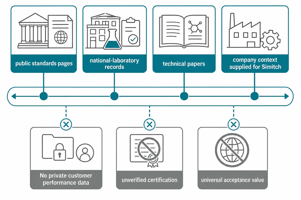
This guide synthesizes public standards pages, national-laboratory records, technical papers, and the company context supplied for Simitch. Configuration-specific results stay attributed and bounded. No private customer performance data, invented production limits, unverified certification, or universal acceptance value is used.
References & Sources
- American Welding Society, Busting the Myths Around Welding Aluminum, 2025
- Oak Ridge National Laboratory, die design and friction self-piercing riveting of AA7055-T76
- SAE 2000-01-2681, riveted, resistance-welded, and hybrid joint comparison
- SAE 2007-01-1703, spot friction welding of aluminum and steel
- SAE 831816, corrosion performance of steel self-piercing rivets in aluminum, 1983
- ASTM D3933-98(2025), preparation of aluminum surfaces for structural adhesives
- ISO 17662:2025, calibration, verification, and validation of welding equipment
- Federal Acquisition Regulation 11.002, policy for describing agency needs
![Hot-Melt Connection Molds & Equipment Guide [2026]](https://simitch.com/wp-content/uploads/2026/09/hot-melt-connection-molds-equipment-guide-featured-768x512.png)