Get in touch with Suzhou Simitch Machinery Co., Ltd Company

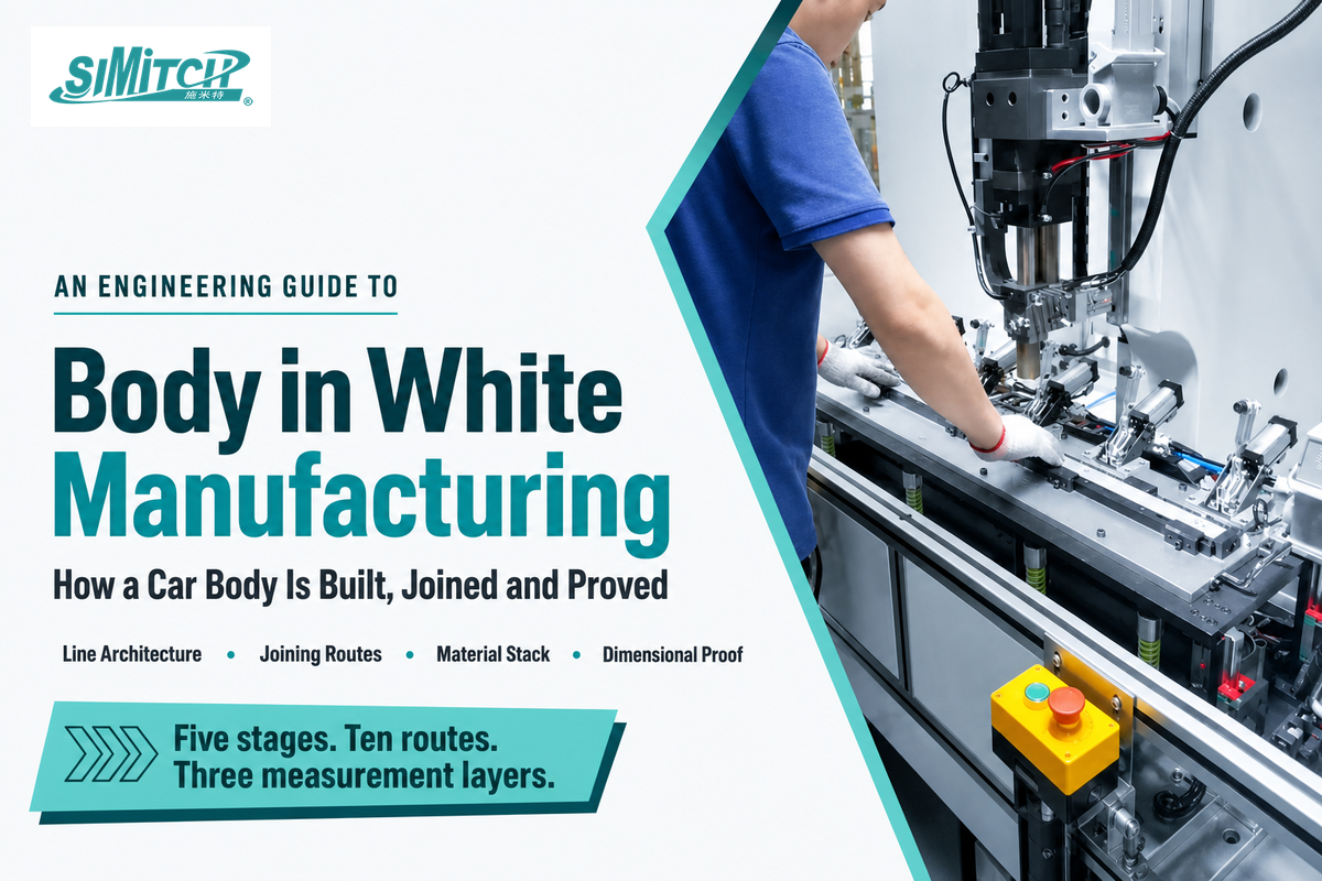
Body in white manufacturing is the stage of automotive manufacturing where stamped panels become one joined body shell, after the press shop, before paint and trim. This guide walks the body shop station by station: what each stage produces, which joining process belongs at which station, how the material stack and station access decide that routing, and how the finished body structure is proved dimensionally correct.
Updated August 2026 · By XCX
Quick Specs
| Process boundary | Starts after stamping, ends before the paint shop |
| Body shop stages | Five: sub-assembly, underbody, framing, closures, finish and inspection |
| Framing-station activities | 45 s to 56 s depending on vehicle size (Al-Zaher, ElMaraghy and Pasek, 2013) |
| Resistance spot welds per body | Four published sources give four different figures between about 3,000 and 7,000 |
| Routing variable | Station access class first, material stack second |
Body in white manufacturing joins stamped panels into a complete, unpainted body structure across five body shop stages. Each station is defined by its access class and material stack, and those two constraints decide the joining process before cost does.
Key points
- Station access disqualifies a joining process before the alloy does. Any gun that can’t reach both sides of the joint is out, whatever the sheet is made of.
- There’s no settled number of spot welds in a car body. Four sources publish four different figures, and this article prints the spread instead of picking one.
- Mega-casting genuinely removes joining operations, but a July 2026 peer-reviewed review calls it a platform-dependent technology rather than a universal replacement.
- Clinching joined two 780 MPa steel sheets that self-pierce riveting could not, in a 2021 study that tested both processes on the same stacks.
- Under the new European machinery rules, converting a line can make the operator the manufacturer of the modified machinery.
Where Body in White Sits in Automotive Manufacturing
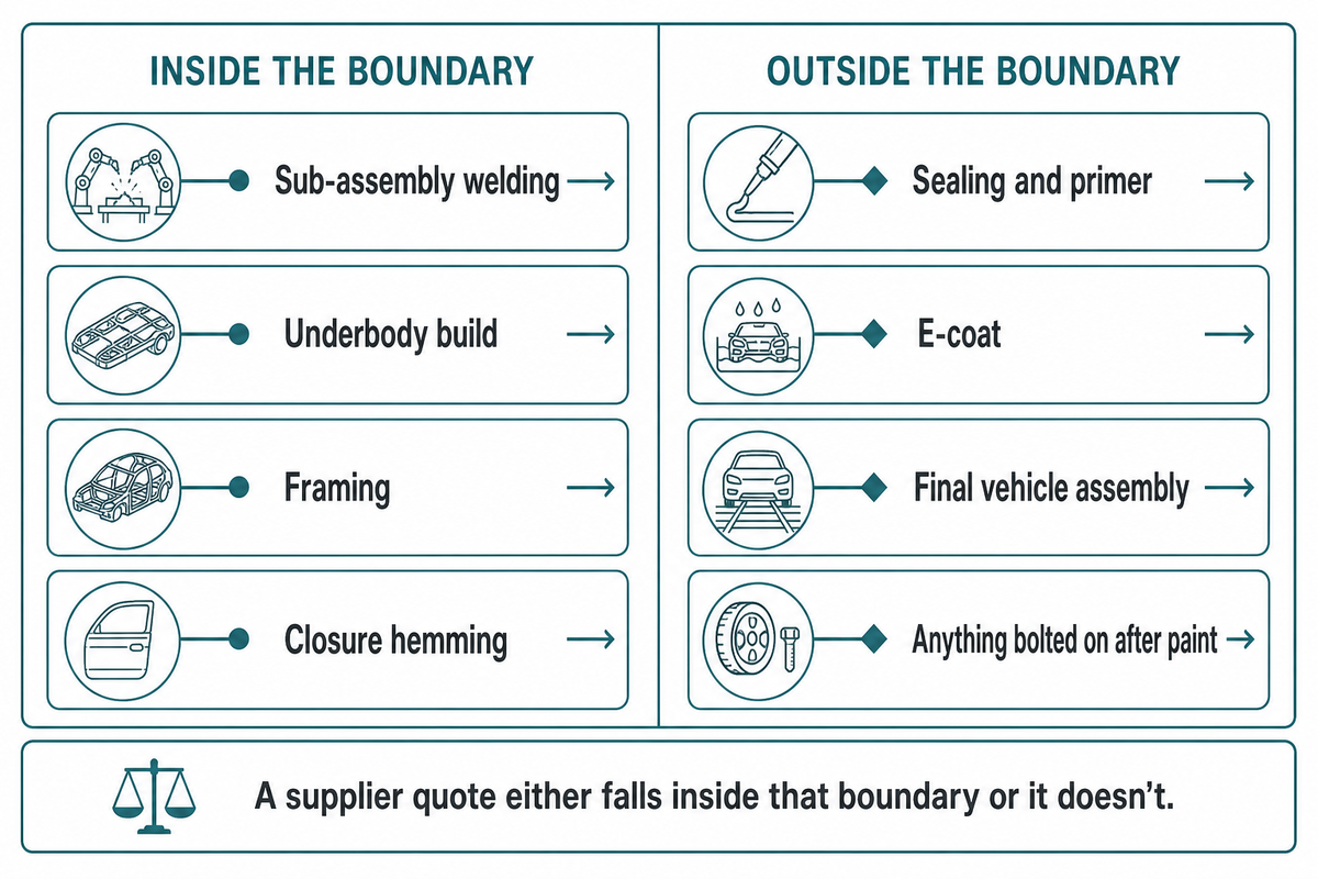
Body in white covers everything between the press shop and the paint shop. Stamped panels arrive as loose parts and leave as one joined body shell with closures hung. Powertrain, suspension, interior, glass and paint all sit outside the boundary. That name describes the bare, unpainted body structure as it leaves the body shop.
Scope matters commercially here, because a supplier quote either falls inside that boundary or it doesn’t. Inside: sub-assembly welding, underbody build, framing, closure hemming, and the joining of every body component that carries load, the body frame itself, the fender mounting structure, and the chassis sub-assemblies welded into the platform. Outside: sealing and primer, e-coat, final vehicle assembly, and anything bolted on after paint, including bumper beams and covers and the chassis components that hang off the subframes. Car bodies at this stage have no wiring, no seats and no doors trimmed, only the welded, riveted and bonded structure plus the panels that hang on it.
The term itself dates from an era when finished bodies were treated with a white primer coat before painting, and the label survived the practice. In the automotive industry the acronym BIW is used freely once the phrase has been introduced, though it’s worth knowing that the bare three letters aren’t owned by this subject in United States search results: queries for the acronym alone return a shipbuilder far more often than a body shop. This run’s own keyword measurement puts the bare acronym at 4,400 monthly United States searches, demand that belongs to a shipyard brand rather than to a body shop, and puts hemming, the closure operation described later on this page, at 40,500, nearly all of it garment sewing. Suppliers also write the same thing several ways: automotive body in white, automotive body-in-white, automotive BIW, and all of them name the same production process stage. The same holds for the metal: a US supplier writes the pairing steel and aluminum, and the spelling is the only thing that changes.
Another terminology trap catches buyers regularly. In American English, body shop is the collision-repair trade. Searching for body shop cycle times in a United States context returns paint-and-dent workshops, not production lines, which is why supplier research on this topic so often collapses into consumer results. The main body of a unibody vehicle is also frequently confused with the chassis. On a body-on-frame truck the chassis is a separate ladder frame; on a unibody car the body structure is the chassis, with front and rear subframes bolted into it.
This article is about the line, not about generic joint selection. Where a reader needs the process-family comparison rather than the station view, the sibling guide linked further down covers it.
From Blank to Body: The Five Stages of a Body Shop
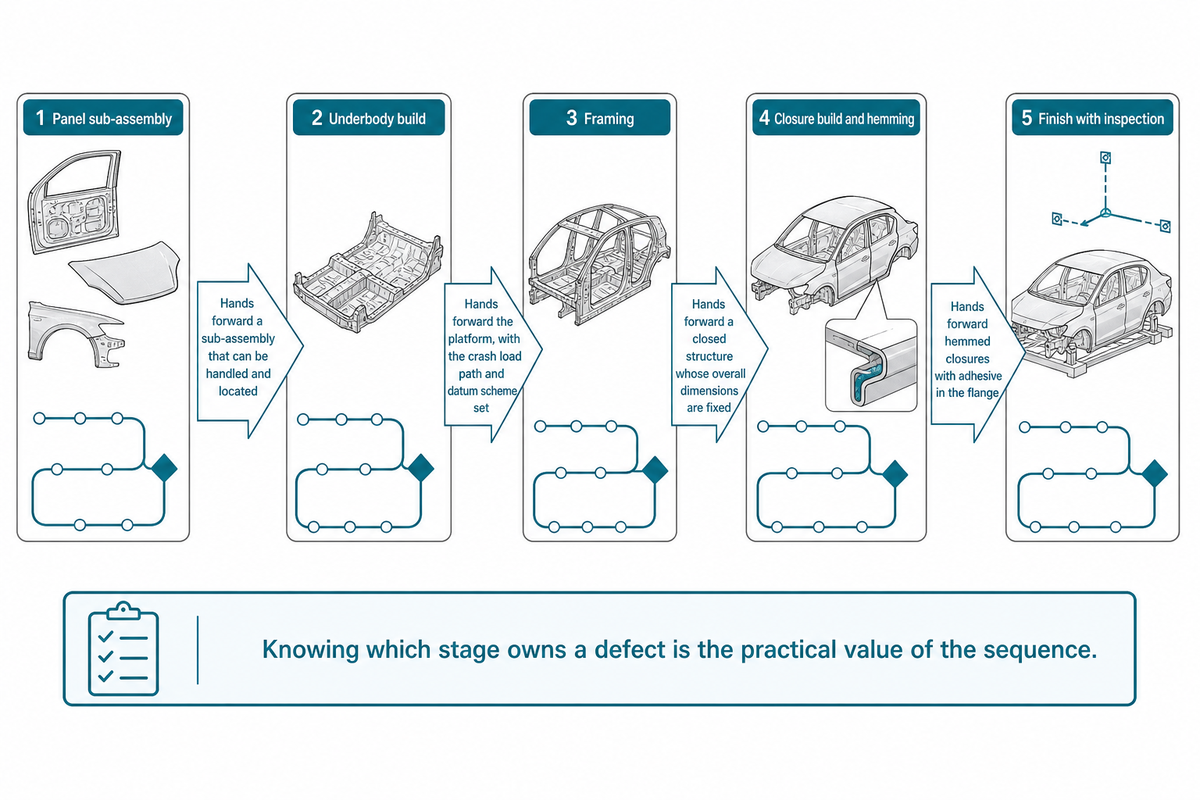
A body shop runs five stages in sequence: panel sub-assembly, underbody build, framing, closure build and hemming, and finish with inspection. Each stage takes joined sub-units from the one before it and hands a larger, stiffer structure to the one after. Knowing which stage owns a defect is the practical value of the sequence.
- Panel sub-assembly — loose stampings are joined into small welded units: rails, pillars, wheelhouses, dash panel. Input is a stamped blank; output is a sub-assembly that can be handled and located.
- Underbody build — front floor, rear floor and the longitudinal rails are joined into the platform. This stage sets most of the crash load path and the datum scheme the rest of the build inherits.
- Framing — bodysides, roof and underbody are clamped in a framing fixture and joined while the whole geometry is held. Framing is where the body first becomes a closed structure, and it is the stage that fixes overall dimensions.
- Closures — hood, doors and tailgate are built separately. Outer and inner panels are joined by hemming, a cold forming operation that folds the outer skin over the inner, usually with adhesive in the flange. Closures are hemmed rather than welded because a weld nugget would show through a class-A surface.
- Finish and inspection — closures are hung and adjusted, gaps and flushness are set, and the body structure is measured before it is buffered ahead of paint.
Naming the stages has a diagnostic value. A gap complaint on a door is a closure and finish problem; a twisted load path is a framing problem; a rattling reinforcement is a sub-assembly problem. Treating the whole manufacturing process as one undifferentiated block is what makes body shop defects so hard to route to an owner. One joint sits slightly outside the five-stage description: an exterior seam that has to read as invisible, such as an aperture edge, is laser brazed rather than welded, because a braze bead can be brought to a class-A surface. Which stage owns which joint is fixed early in the development process, and body shop assembly lines are laid out around that decision.
What are the stages of BIW manufacturing?
BIW manufacturing runs from stamped blank to measured body shell in five stages. Sub-assembly joins loose stampings into handleable units. Underbody build creates the platform and its datum scheme. Framing clamps bodysides, roof and underbody together and joins them while the geometry is held. Closure build produces hood, doors and tailgate, hemmed rather than welded so no joint shows on a visible surface. Finish and inspection hangs the closures, sets gaps and flushness, and measures the structure.
Each stage adds stiffness, and each is harder to correct than the one before it.
Line Architecture: Stations, Cycle Time and Where Capacity Goes
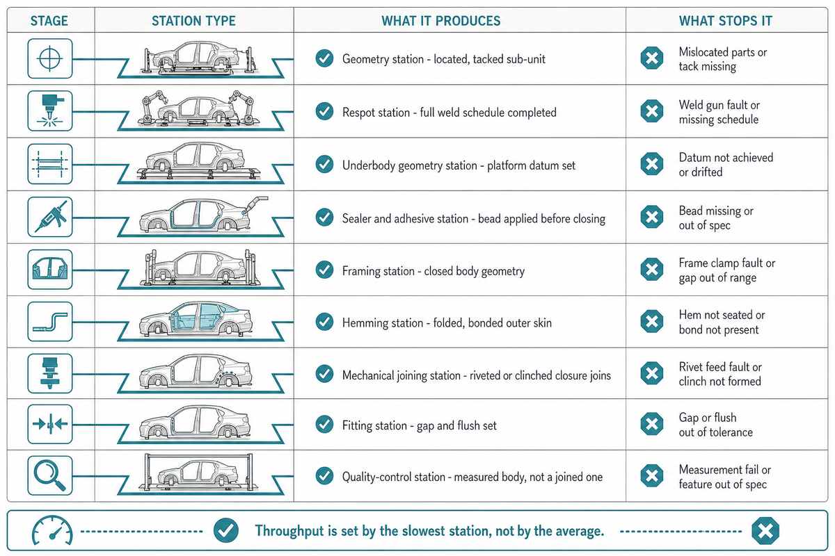
A body shop line is a chain of stations, and not all of them join anything. Stations divide into geometry-setting stations that locate parts and make the first joins, respot stations that add the remaining joins once geometry is fixed, and quality-control stations that measure. Throughput is set by the slowest station, not by the average.
That division of labour has been stable for three decades. Ceglarek and Shi described the geometry station and respot station split in their 1995 work on dimensional variation in autobody assembly, and engineers at Stellantis describing their own Sochaux line still call the second group “geospots”. Stellantis reported the results of a body shop redesign as six assembly steps reduced to five, 14 % fewer geospots, 20 % fewer robots and a 30 % target reduction in unique fixtures; those are Stellantis-reported figures from an AutoForm simulation-software case study, not independently audited. Lines of this type carry hundreds of fixtures, and multi-model fixtures are the main cost lever available to a plant that builds more than one body on the same line, and they’re what makes flexible manufacturing possible without building a second one. Most of the joining is robotic: a respot station is a cluster of robotic welding arms working a fixed sequence, and automotive engineers size those clusters from joins per cycle rather than from floor area.
10-Station Body Shop Cycle Ledger
The 10-Station Body Shop Cycle Ledger reads a station list as a capacity statement: what each station type produces, how many a stage carries, and what stops it.
| Stage | Station type | What it produces | Station count character | What stops it |
|---|---|---|---|---|
| Sub-assembly | Geometry station | Located, tacked sub-unit | Many, run in parallel branches | Panel variation, fixture wear |
| Sub-assembly | Respot station | Full weld schedule completed | Fewer than geometry stations | Electrode dressing, tip wear |
| Underbody | Geometry station | Platform datum set | Few, high consequence | Datum conflict between suppliers |
| Underbody | Sealer and adhesive station | Bead applied before closing | One per closing sequence | Bead placement, open time |
| Framing | Framing station | Closed body geometry | One, occasionally two | Fixture changeover between models |
| Framing | Respot station | Remaining structural joins | Several in series | Robot reach and gun interference |
| Closures | Hemming station | Folded, bonded outer skin | One per closure family | Flange cracking, adhesive cure |
| Closures | Mechanical joining station | Riveted or clinched closure joins | One to a few | Fastener feed and die life |
| Finish | Fitting station | Gap and flush set | Manual or semi-automatic | Accumulated stack-up |
| Finish | Quality-control station | Measured body, not a joined one | Inline plus offline sampling | Measurement takt, not join takt |
Two numbers turn that ledger into capacity. First comes station takt, which is simply 3,600 ÷ jobs per hour. Second comes a real cycle band to test it against: Al-Zaher, ElMaraghy and Pasek, publishing in the Journal of Manufacturing Systems in 2013, report that in most production systems the time set for framing-system activities is 45 s to 56 s, depending on vehicle size, with smaller bodies at the shorter end. That band belongs to framing-station activities, not to whole-line takt. Framing is also the manufacturing stage that fixes the vehicle’s overall dimensions, so time pressure there surfaces later as gap and flushness variation rather than as a missed count.
Worked example. Take a body shop asked to deliver 60 jobs per hour: station takt is 3,600 ÷ 60 = 60 s. Over two shifts of 7.5 hours, that’s 60 × 15 = 900 bodies per day. If the framing station is running at the 56 s end of the published band, it fits inside a 60 s takt with 4 s of margin; if the plant then raises the requirement to 66 jobs per hour, takt falls to 3,600 ÷ 66 ≈ 54.5 s and the same framing station becomes the constraint. Nothing about the joining process changed. A published interview study of mega-casting adoption records practitioners describing a fall from a 60 s body shop cycle to 45 s, attributed there to expert code E71; that is a single indexed quotation from one study, and it’s quoted here as an order-of-magnitude agreement rather than as a second measurement.
One more architectural fact keeps the takt discussion honest. As Magna’s contract-manufacturing engineers describe their own multi-model operation, the body shop doesn’t have to run in final-assembly sequence, because bodyshells are buffered before paint. Each body shop optimises for its own changeover cost; the buffer absorbs the difference.
What is a BIW engineer?
A BIW engineer owns the feasibility and geometry of the joined body structure rather than the styling of it. That role covers weld and joint feasibility, whether a gun, rivet setter or clinching head can physically reach every joint on the specified stack.
Fixture concept, datum scheme ownership and tolerance allocation across the assembly round out the role. Tolerance allocation is the decisive one: the engineer decides which features get tight tolerances and which absorb variation, because a body can’t be built to uniform precision everywhere at reasonable cost. In practice the position sits between product design and manufacturing systems, translating a body architecture into a station sequence that automation can actually execute, and pushing back on BIW design decisions whose joints no equipment can reach. It also owns the split of the shell into BIW components that can be built in parallel and brought together at framing.
What the Press Shop Hands the Body Shop
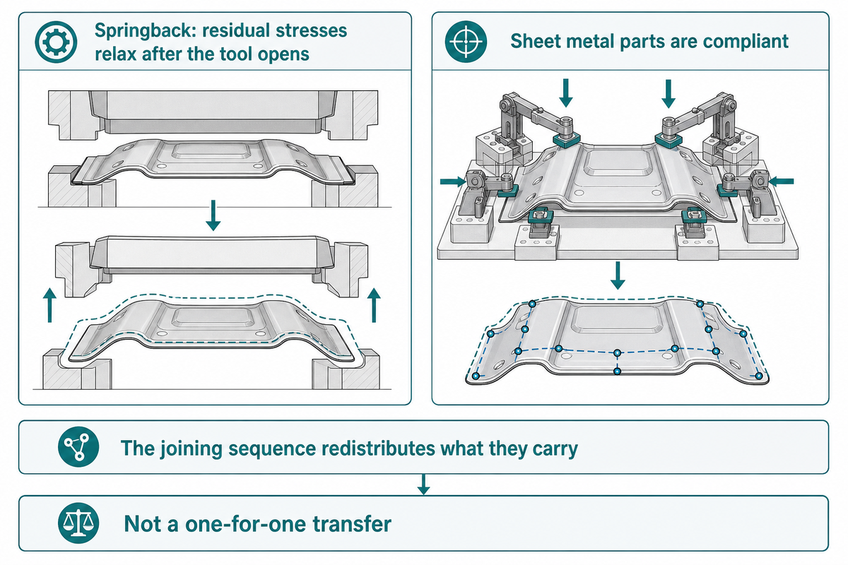
Stamping problems reach the body shop as fit problems, but not as a one-for-one transfer. Springback, directional material properties and blank variation change the shape of the panel that arrives at the fixture. Bodies then absorb part of that variation, because sheet metal parts are compliant and the joining sequence redistributes what they carry.
Springback is the shape change that happens when residual stresses created during forming relax after the tool opens. It is difficult enough to predict that the National Institute of Standards and Technology built a springback cup test at the direct request of USCAR, the United States automotive research consortium, precisely because prediction accuracy drives how many die iterations a vehicle manufacturing programme pays for. The same NIST work on sheet metal formability reported that flow stress and the strain hardening exponent both differ between the rolling and transverse directions on DQSK, HSLA and DP600: a stamped panel doesn’t have the same properties in every direction. It also found that deformation-induced surface roughness is non-Gaussian, which means Ra and Rq structurally under-describe a stamped surface.
What a body shop inherits, then, is a distribution rather than a dimension. Volvo engineers publishing at SAE in 1995 set functional-geometry targets of no more than 0.2 mm spread in stamped parts, 0.5 mm in pre-assembled parts and 0.7 mm in complete car bodies. That’s one source and one programme, and it’s quoted here as the historical benchmark it is, not as a current industry specification.
That caveat matters more than the numbers. Panel variation doesn’t transfer deterministically into the finished body. Compliant components absorb individual component variability, a result traced to Takazawa in 1980 and restated in a 2016 Australian National University thesis on assembly variation; joining sequence and fixture boundary conditions co-determine the outcome. Treat press-shop variation as an input to a stack-up, and the burden lands where it belongs, on fixturing and joining sequence, which are equipment decisions. The same thesis puts the scale of that equipment problem plainly: a vehicle carries roughly four to six thousand joins, and the author estimated around 300 billion joining operations performed annually worldwide as of 2016.
Resistance Spot Welding: The Backbone, and Where It Stops Working
Resistance spot welding dominates the body shop because it’s fast, needs no consumable filler, and suits a robot with a C-frame or X-frame gun. It works when the gun can reach both sides of the joint, when the stack conducts and melts predictably, and when the surface condition is stable. Each of those three is a boundary, not a guarantee.
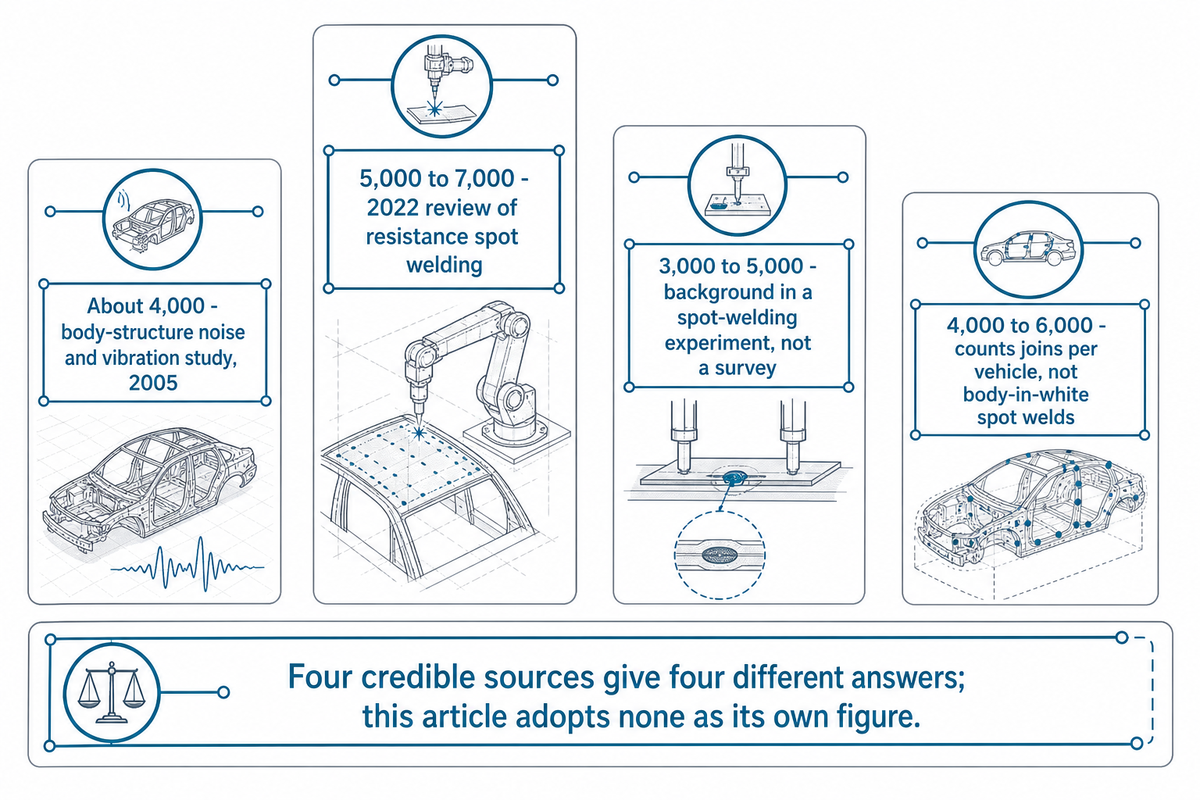
Ask how many spot welds a car body has and four credible sources give four different answers. What follows reports those four as published; this article adopts none of them as its own figure. A body-structure noise and vibration study by Donders and colleagues, published in 2005, works with about 4,000, a count assembled for a finite-element model of one body. A 2022 review of resistance spot welding in automotive applications reports 5,000 to 7,000, carried from the literature it surveys rather than measured by its authors. Two further published figures give 3,000 to 5,000 and 4,000 to 6,000. The first is background carried in a resistance spot welding experiment rather than a survey result of its own, and it was read here from a citation excerpt rather than from the full paper; the second counts joins per vehicle rather than spot welds in the body-in-white. Those spreads aren’t rounding of one another, and they aren’t produced the same way either. Vehicle size, body architecture and whether adhesive carries part of the load all move the count, and no source states its vehicle mix. Printing a single figure would be the easiest way to be confidently wrong, so this article prints the disagreement.
The weldability of a given stack is assessed against ISO 18278-1:2022, which sets out the procedures for evaluating resistance weldability of metallic materials. Its 2022 edition is the current one; the process is old enough that citing a superseded edition is a live risk.
Where does the welding process stop being the right answer: when does another joining method have to take over? Three conditions decide it. First, access: a two-sided gun that can’t reach the far side of the joint is disqualified before any metallurgical argument starts, and closed sections, deep cavities and late-sequence joints create exactly that condition. Second, coated and dissimilar surfaces: zinc coatings change the contact resistance and shorten electrode life, so the weld schedule and the dressing interval both move, and electrode compatibility with the coating becomes part of the process window rather than an afterthought. Third, aluminium. Aluminium’s high thermal conductivity, tenacious surface oxide and lower melting point make aluminium and mixed stacks, in the words of a 2021 comparative study, “not easy” for the process, which is the accurate phrasing, and deliberately not “impossible”. What the process does at that boundary is covered in the materials section below.
Mechanical and Hybrid Joining: Riveting, Clinching, Flow-Drill Screws and Adhesive
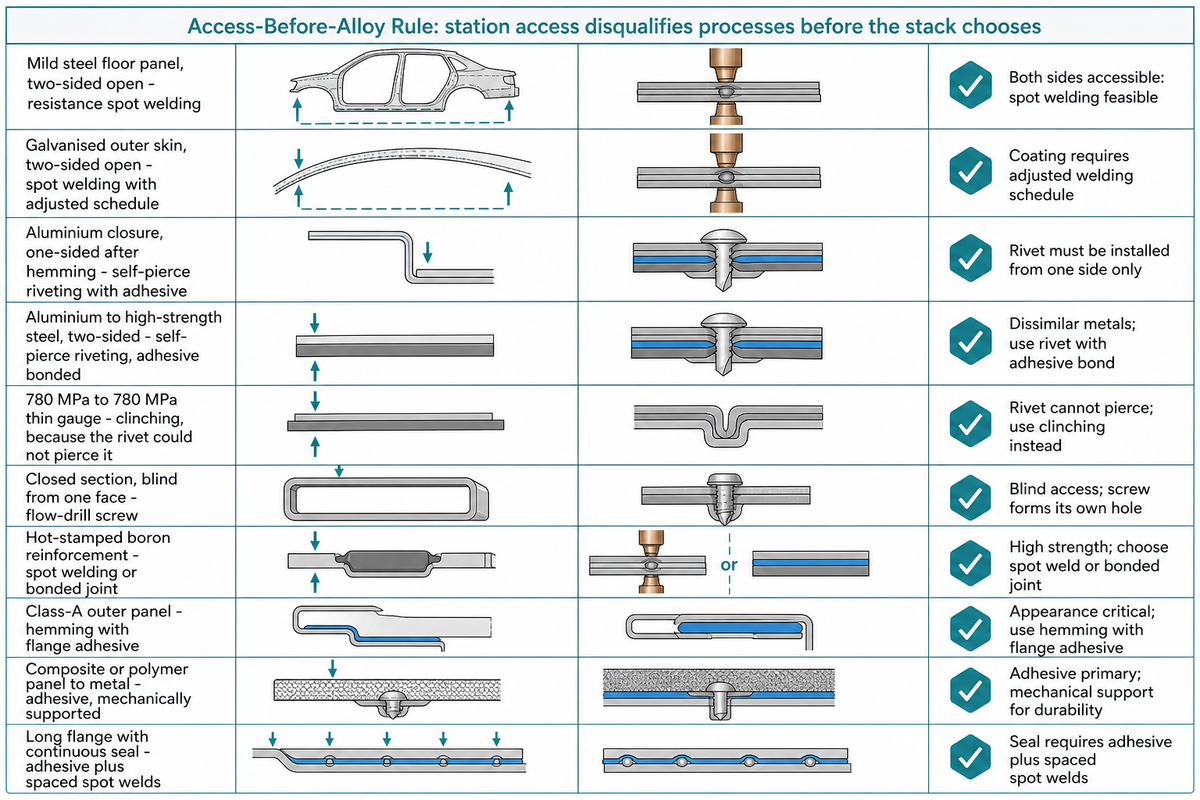
When resistance spot welding runs out of window, four routes take over: self-pierce riveting, clinching, flow-drill screws and structural adhesive, usually in combination. Access decides before strength does. The call is made on whether the station can reach the joint, and only then on what the material stack allows.
Access-Before-Alloy Rule
Access-Before-Alloy Rule: station access class disqualifies joining processes before the material stack selects among the survivors. It applies to vehicle-body stacks at body shop stations and is not offered as a general sheet-metal rule.
Read it as an ordering, not a preference. Two-sided processes need a gun throat that clears the part on both faces; one-sided processes need only a nose and a reaction path. If the joint sits inside a closed section that the body has already become, every two-sided candidate is gone, and the alloy question never gets asked. Reversing the order (picking the process from the material and then discovering the robot can’t get there) is the most common way a joining concept has to be rebuilt late.
Stack-and-Access Route Card
The Stack-and-Access Route Card reads a vehicle-body material stack plus its station access class, then returns the process and the one constraint that decided it.
| Body stack | Station access | Routed process | Deciding constraint |
|---|---|---|---|
| Mild steel floor panel to reinforcement | Two-sided, open | Resistance spot welding | Nothing rules it out; cost and speed win |
| Galvanised steel to galvanised steel, outer skin | Two-sided, open | Spot welding with adjusted schedule | Coating shortens electrode life; dressing interval |
| Aluminium outer to aluminium inner, closure | One-sided after hemming | Self-pierce riveting with adhesive | Oxide layer and one-sided access together |
| Aluminium to high-strength steel, mixed body | Two-sided available | Self-pierce riveting, adhesive bonded | Dissimilar metals; cold joining avoids intermetallics |
| 780 MPa steel to 780 MPa steel, thin gauge | Two-sided available | Clinching | Rivet could not pierce the stack in published tests |
| Closed section, joint reachable from one face only | One-sided, blind | Flow-drill screw | No reaction die can be placed behind the joint |
| Hot-stamped boron steel reinforcement | Two-sided, open | Spot welding or bonded joint | Hardness defeats piercing fasteners |
| Class-A outer panel where a mark is unacceptable | One-sided visible face | Hemming with flange adhesive | Surface appearance, not strength |
| Composite or polymer panel to metal structure | Either | Adhesive, mechanically supported | Thermal expansion mismatch over service life |
| Long flange with continuous seal requirement | Two-sided, open | Adhesive plus spaced spot welds | Sealing length, not joint count |
Two of those rows deserve their sources, and so does the table’s spine: the hardness and formability limits behind the steel rows come from WorldAutoSteel’s AHSS Application Guidelines, an industry association for steel, which is worth knowing when reading a process-selection limit written by it. The 780 MPa row comes from a 2021 comparative study by Mori and colleagues setting clinching against self-pierce riveting, in which every tested stack was joined by both processes except two 780 MPa steel sheets by self-pierce riveting, which clinching handled. That’s a documented limit on a process this company supplies, and it’s stated here because a routing table that only lists strengths isn’t a routing table. The adhesive row rests on practitioner economics rather than physics: structural bonding earns its place mainly where the number of spot welds needed for equivalent stiffness would cost more process time than a bead of high-performance structural adhesive does.
Changing the process isn’t the same as changing the station. A patent filed by Battelle Memorial Institute under a United States Department of Energy contract states that applying self-piercing rivets “introduce[s] significant change in the body shop operations which add additional cost and lost production when existing operations are utilized”. This is background language from a patent holder, not a neutral comparison. The tooling reality behind that sentence is a setter-and-die pair per joint family, with the die as a consumable; a Ford patent on rivet die management notes that using the wrong die produces “costly scrapped parts and machine downtime”. Rivet feed rates and magazine capacities quoted by equipment vendors are vendor figures for specific machines, not industry norms, and should be read that way in a quotation.
Where a specification names self-pierce riveting, the equipment question follows immediately: the self-pierce riveting cells that serve those stations differ in frame depth, setting force and feed architecture, and those three decide which of the rows above a given cell can actually serve. Where the route is clinching, the clinching press behind that station is selected on throat reach and force envelope in the same way. This article deliberately stops short of the economics; readers who need to compare how these same processes compare on cost per accepted joint will find that treatment in the process-family guide instead, and Simitch’s joining route matrix wizard runs a stack against this same table before anyone writes a specification.
Specifying a Joining Cell: Robots, Grippers, Fixtures and Feed
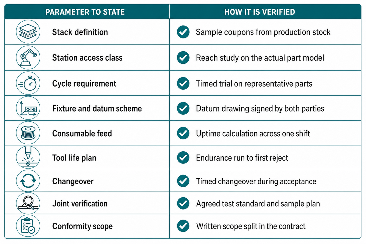
A joining cell isn’t a robot with a process head bolted on. It’s a fixture concept, a part-presentation method, a consumable feed system, a service loop, a changeover plan and a conformity file, and every one of those is a line item a buyer either specifies or inherits by default. Quoting the process head alone is how cell projects overrun.
Start with the regulatory frame, because it changed. Regulation (EU) 2023/1230 replaces Machinery Directive 2006/42/EC and applies from 20 January 2027. Two dates circulate for this, and the reason is worth one sentence: the Official Journal text as first published said 14 January 2027, and a corrigendum published at OJ L 169, 4 July 2023, pages 35–36 replaced it with 20 January 2027 in item 6 of its fourteen corrections. Vendor pages quote one date or the other and almost none explain why. The Regulation also moves the old Annex IV list into Annex I Section A, with a group of categories that require a notified body and no harmonised-standard escape route, treats safety-related software as a safety component, and adds a mandatory protection-against-corruption provision covering cybersecurity.
One clause changes procurement behaviour: substantial modification. A party carrying out a substantial modification of machinery is considered a manufacturer under the Regulation and takes on the Article 10 obligations, including conformity assessment. The own-use exemption in the text is written for a non-professional user, and it does not reach a vehicle maker re-tooling its professional body shop. Read commercially, that inverts the usual retrofit argument: converting an existing line to a new joining process can make the operator the manufacturer of the modified machinery. It is a direct reason to procure an integrated, conformity-assessed cell rather than a bare process retrofit. The Regulation’s separate statutory definition of partly completed machinery draws the same boundary ISO 10218 already drew on its own: Part 1 covers the robot as supplied, Part 2 covers the application and the cell it is installed in. The two are independent instruments, one European Union law and one international standard, and neither one caused the other. What they share is the handover, and a robot supplier’s Part 1 statement does not discharge what attaches to the cell a buyer installs. All of that is European law. A cell going into a North American plant is judged against a different set, starting with the general machine-guarding requirement at 29 CFR 1910.212 and the robot-safety standards published through the US robotics industry association, so the conformity paperwork a supplier owes is settled by destination, not by process.
Then the datum problem, which is what a request for quotation is really about. As Magna’s body shop engineers describe multi-OEM work, docking points are set by vehicle architecture and the integration method differs between original equipment manufacturers: screwed, plugged in or locked. No cell can be specified from a process list alone, because the way the part is presented and held is customer-specific. Vendors market this category as BIW manufacturing solutions, a phrase that stretches from a bare process head to a complete conformity-assessed cell, so the first job of a quotation is to state which BIW welding and assembling operations are in scope and what the BIW positioning and workholding needs of the station are. European BIW lines carry the extra question of who signs the conformity file once the conversion is done.
RFQ checklist — copy these into your quote request:
| Parameter | What to state | Why it matters | How to verify |
|---|---|---|---|
| Stack definition | Every material, grade, coating and thickness in mm, per joint family | Decides process window and tooling | Sample coupons from production stock |
| Station access class | One-sided or two-sided, with clearance envelope | Disqualifies process families before pricing | Reach study on the actual part model |
| Cycle requirement | Joins per cycle and station takt in seconds | Sets head count and robot count | Timed trial on representative parts |
| Fixture and datum scheme | Docking method and datum ownership | Customer-specific; not transferable | Datum drawing signed by both parties |
| Consumable feed | Magazine capacity, refill interval, feed route | Refill stops the station, not the robot | Uptime calculation across one shift |
| Tool life plan | Die or electrode life and dressing interval | Consumables drive real cost per shift | Endurance run to first reject |
| Changeover | Models per line and changeover time | Multi-model fixtures are the main cost lever | Timed changeover during acceptance |
| Joint verification | Inline monitoring and destructive sample rate | Defines what “accepted” means | Agreed test standard and sample plan |
| Conformity scope | Who is the manufacturer of the modified machinery | Article 10 obligations follow the answer | Written scope split in the contract |
Two of those rows are worth pricing before anything else. Consumable feed is the one buyers underestimate most often, because what a magazine refill interval does to station uptime is arithmetic, not opinion. And the scope of the hardware itself (the riveting hardware behind the fastening routes, servo press systems where the station is press-driven) belongs in the quote alongside the process head, not after it.
Where this article draws the line on quotation scope: a request for quotation that omits the full stack, every grade, coating and thickness per joint family, and leaves the consumable feed unpriced is not a specification. It is a scope negotiation deferred to commissioning. Those two rows decide more of a joining cell’s real cost than the process head does.
Materials: Why the Body Decides the Joining Process
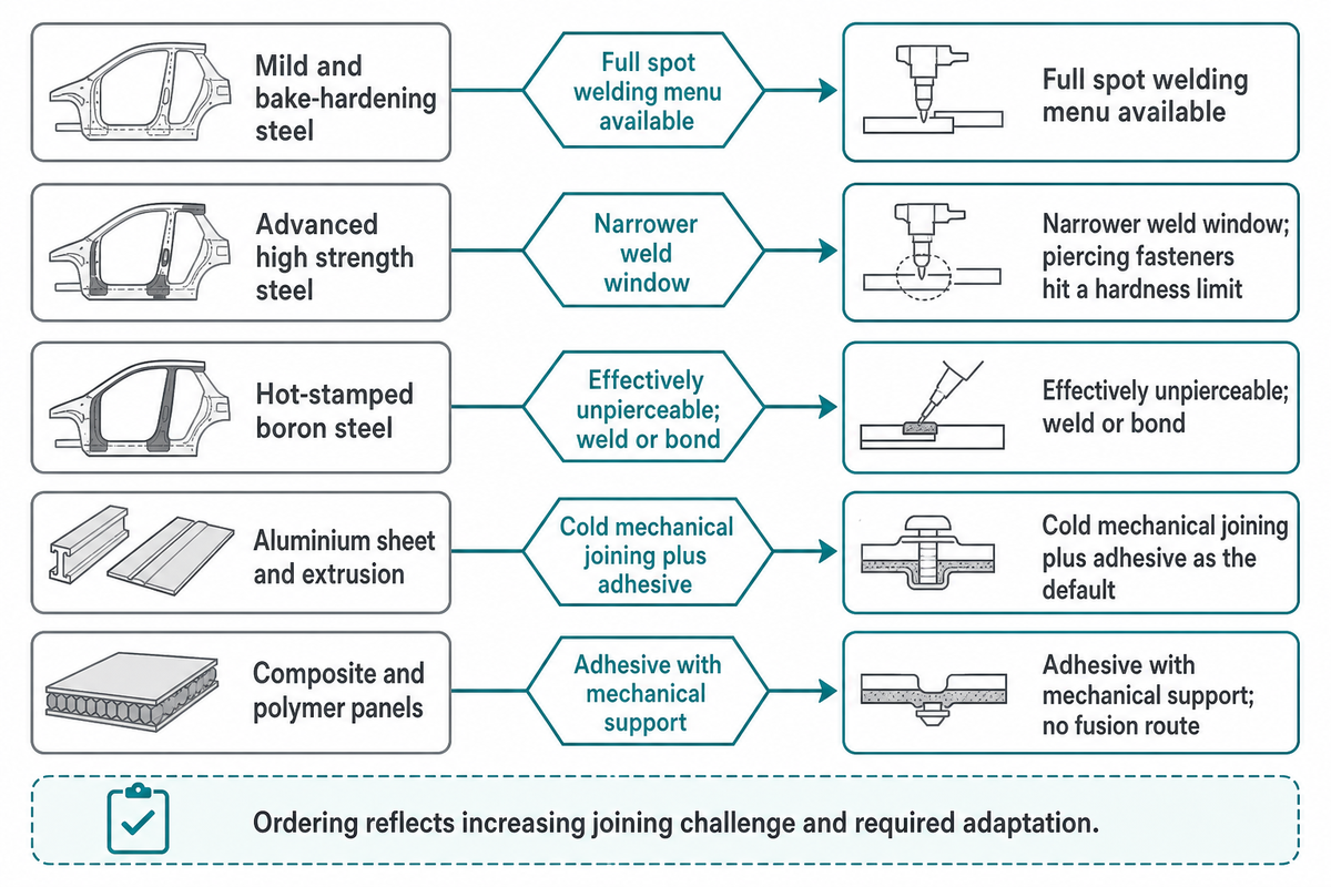
The material mix in a body structure sets the joining menu before anyone specifies equipment. Mild and galvanised steels keep the full welding option open. Advanced high-strength grades narrow it. Aluminium and mixed stacks push the line toward cold mechanical joining and adhesive, and toward the capital that goes with them.
An honest version of the aluminium constraint is narrower than the usual one. Conventional resistance spot welding, as installed, tooled and staffed in a steel body shop, falls outside its process window on aluminium and mixed stacks. A specialised welding process derived from it can reach them: Oak Ridge National Laboratory describes General Motors’ multi-ring domed electrode with multiple solidification weld schedules, developed expressly to make use of existing infrastructure and workforce competency, and extended from aluminium-to-aluminium to aluminium-to-steel joints. Reaching them costs new electrodes, new weld schedules, and a nondestructive evaluation problem that’s still open. That’s a different statement from “aluminium cannot be spot welded”, and the difference is what a capital plan turns on.
| Material family | Why it is used | Joining consequence |
|---|---|---|
| Mild and bake-hardening steel | Formability, low cost, class-A surface | Full spot welding menu available |
| Advanced high strength steel | Crashworthiness and impact resistance at lower mass | Narrower weld window; piercing fasteners hit a hardness limit |
| Hot-stamped boron steel | Intrusion resistance in pillars and rails | Effectively unpierceable; weld or bond |
| Aluminium sheet and extrusion | Use of lightweight materials in closures and underbody | Cold mechanical joining plus adhesive as the default |
| Composite and polymer panels | Mass and part consolidation | Adhesive with mechanical support; no fusion route |
Lightweighting is why the mix exists at all: mass targets, not manufacturing preference, are what put three material families into one body structure. Clinching and self-pierce riveting sidestep the dissimilar-metal problem for a specific reason: both are cold processes, so no intermetallic layer forms at the interface between steel and aluminium. Corrosion, though, still has to be designed for. The 2021 study cited above ran a neutral salt-spray series of 1,176 hours and reported bare steel-to-steel clinched joints losing about 85 % of their load, bare steel-to-aluminium joints losing about 20 % whether clinched or riveted, galvanised steel-to-aluminium about 11 %, and aluminium-to-aluminium almost unaffected at 1 % and 3 %. On the same aluminium-to-aluminium stack, the riveted joint carried more than twice the tension-shear load of the clinched one. One design rule buried in that data is the useful part: where the joint was formed without gaps in cross-section, corrosion didn’t reach the joint even at 1,176 hours, and the load loss came from sheet thinning outside it. Joint tightness, not fastener choice, governs corrosion life. The test stacks were JSC780 and galvanised JAC780 at 1.2 mm, with A5052 at 1.5 mm for structural panels and 1.0 mm for outer panels.
What are the types of BIW?
Four body architectures cover most of what a body shop builds. A unibody, or monocoque, integrates the floor, rails and pillars into one load-carrying shell and is what nearly every passenger car uses; the body structure and the chassis are the same object.
Space frames carry load through a skeleton of extrusions and castings with non-structural skins hung on them, which suits low volumes and aluminium-intensive designs. A multi-material body mixes families deliberately (hot-stamped steel where intrusion resistance is needed, aluminium where mass matters, composite where neither applies) and pays for it in joining complexity. A body-on-frame vehicle keeps the two apart: the cab or body shell is built in the body shop and bolted later onto a separate ladder frame that carries suspension and powertrain loads. Full-size pickups and the sport utility vehicles derived from them still use it, and it’s the one architecture where body in white and chassis name genuinely different assemblies. Electric-vehicle platform bodies are increasingly a fifth case in practice: a structural battery enclosure takes over part of the underbody’s load path, which moves sealing, service access and joint accessibility to the top of the design constraint list.
Mega-Casting and Electric Vehicle Platforms: What Happens When Automotive Parts Disappear
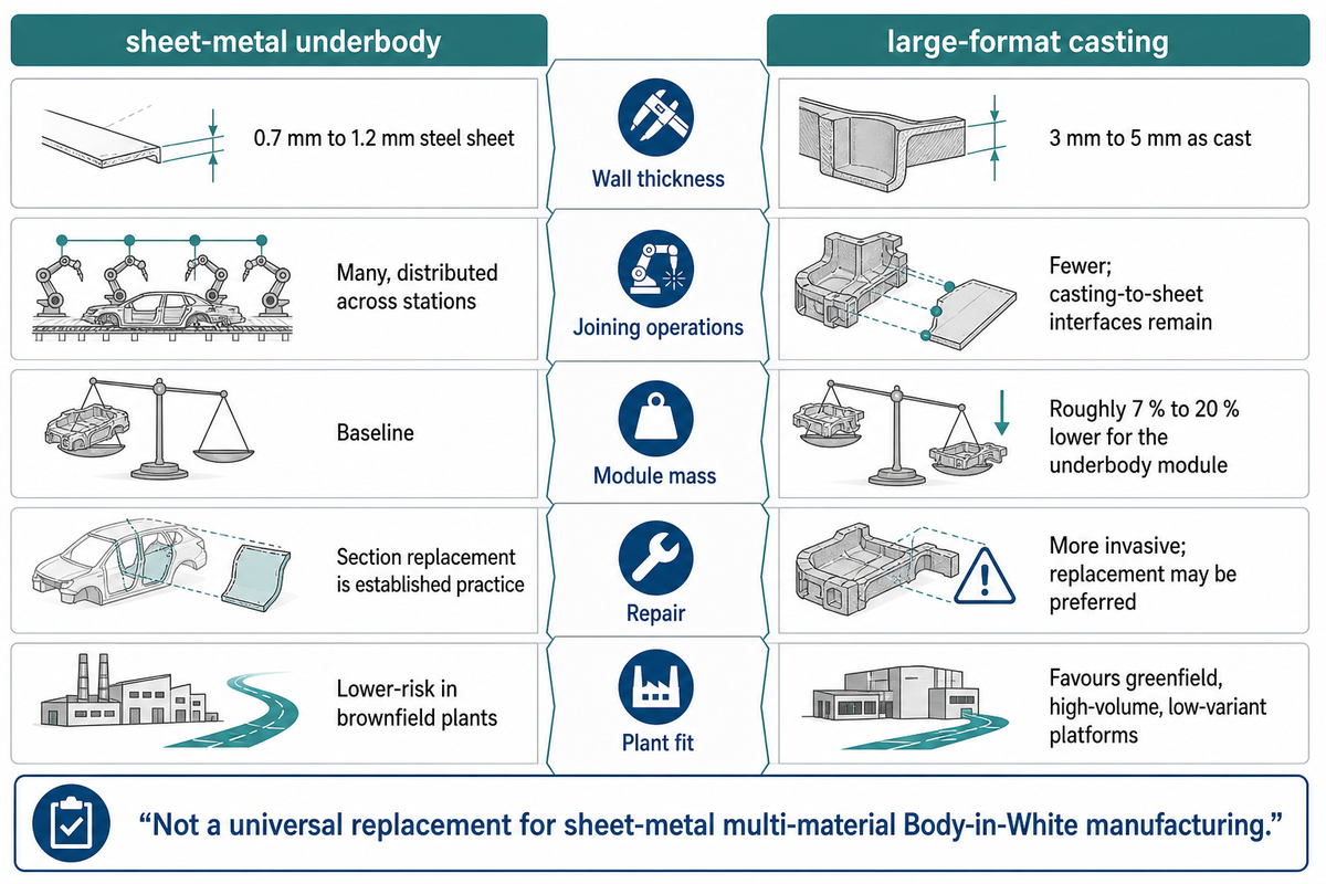
Large-format casting replaces dozens of stamped and joined parts with one aluminium casting, and it genuinely reduces the number of joining operations in the automotive industry’s newest platforms. What it doesn’t reduce is total system difficulty. Defect sensitivity, dimensional distortion, property variation and repairability move in as the joining stations move out.
Concede the first half plainly, because the peer-reviewed literature does. A review published in the Journal of Manufacturing and Materials Processing on 23 July 2026 examines gigacasting against sheet-metal body construction and concludes that it “should not be regarded as a universal replacement for sheet-metal multi-material Body-in-White manufacturing but as a platform-dependent technology”. Operation count and system difficulty are separate axes, and the popular version of this story collapses them into one.
That commercial hinge sits in the same review. It places gigacasting’s attraction in high-volume, low-variant electric-vehicle platforms and greenfield production, while conventional sheet metal retains lower-risk implementation in brownfield plants. Most re-tooling projects are brownfield. That argument is being made here in a peer-reviewed academic review rather than on an equipment supplier’s page, which is the way a buyer should want it.
| Dimension | Sheet-metal underbody | Large-format casting |
|---|---|---|
| Wall thickness | 0.7 mm to 1.2 mm steel sheet | 3 mm to 5 mm as cast |
| Joining operations | Many, distributed across stations | Fewer; casting-to-sheet interfaces remain |
| Module mass | Baseline | Roughly 7 % to 20 % lower for the underbody module, as reported in the 2026 review |
| Repair | Section replacement is established practice | More invasive; replacement may be preferred |
| Plant fit | Lower-risk in brownfield plants | Favours greenfield, high-volume, low-variant platforms |
Press size is the second place where sources disagree, and the disagreement is handled the same way as the spot-weld count. ASSEMBLY Magazine, reporting Bühler’s head of product management in December 2025, gives ultra-large press locking force as 6,000 tons to 9,000 tons; the 2026 review says “typically in the range of 5,000–12,000 tons”. The first figure comes from an equipment builder describing its own machine class, the second from a 2026 peer-reviewed review. Both are published, neither is presented here as settled.
The underbody mass figure in the table above needs the same label: roughly 7 % to 20 % is what the 2026 review reports across the programmes it surveys, not a measurement the review made itself, and it applies to the module rather than to a whole body. Mass claims deserve that discipline generally, and the next one is the most useful thing in this section. In the review’s computer-aided engineering benchmark, an aluminium giga-cast front end came in at 76 kg against 83 kg for an optimised advanced and ultra-high-strength steel design: casting wins. On the casting-equivalent portion alone, the steel alternatives were lighter, roughly 70.3 kg against 74.7 kg: steel wins. Both results are from the same study. The paper’s own rule is the one to carry into a specification: mass comparisons “must be made on a functionally equivalent basis and cannot be inferred from material density alone”.
Adoption is real but uneven across global automotive production. Volvo leads in Europe with megacast rear floors while most German car manufacturers are still piloting, and BYD, Geely’s Zeekr brand, Li, NIO and XPeng already run gigacast modules in production. Whether a given automaker follows depends on platform volume and variant count more than on the technology. Repairability remains a first-order obstacle rather than a footnote: cast repair procedures are more invasive and expensive, manufacturer guidance may favour replacement after a crash, and, as the same 2026 review reports, General Motors has been exploring modular cut-and-replace zones as a response. On the production side, a published interview study of mega-casting adoption records practitioners expecting a scrap rate of at least 10 % on a mega-casting chain, attributed there to expert code E191; a corroboration attempt for that figure failed, and it’s reported here as one study’s indexed quotation rather than as an industry rate.
One point of demand discipline, since this section reads like a trend story. This article makes no claim about the size or growth of the automotive BIW market, because none was researched. This run’s own keyword sampling reads flat or stable across nearly all of this topic cluster over a full twelve-month window. Nothing here is driven by a surge of interest; it’s an engineering shift, and it should be evaluated as one.
Dimensional Quality: Proving the Body Is in Tolerance
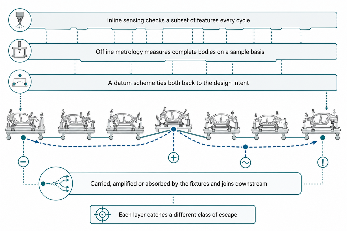
A body shop proves dimensional correctness in layers, not with one measurement. Inline sensing checks a subset of features every cycle, offline metrology measures complete bodies on a sample basis, and a datum scheme ties both back to the design intent. Each layer catches a different class of escape, and none of them substitutes for the others.
Layers are necessary because of variation propagation. Ceglarek and Shi showed that a deviation introduced at one station doesn’t necessarily appear as a defect at that station; it’s carried, amplified or absorbed by the fixtures and joins downstream, and shows up somewhere else. That’s why measuring only the finished body tells you a body is wrong without telling you which station made it wrong, and why measuring only at the source misses interactions that the assembly itself creates.
Three layers do the work in practice. Inline sensing (vision or laser measurement built into a station) gives every-cycle coverage of a limited feature set and catches drift quickly. Offline coordinate metrology gives complete coverage of a small sample and catches form errors that inline features miss. Fixture and datum audit checks the measuring reference itself, which is the layer people skip and then regret, because a drifted fixture makes every downstream measurement precisely and consistently wrong. Surface profile tolerance zones for body panels are described in FARO’s technical guidance on automotive assembly geometric dimensioning and tolerancing; treat that as a vendor’s practical explanation, not as a standard.
The 1995 Volvo functional-geometry work quoted earlier, 0.2 mm in stamped parts, 0.5 mm in pre-assembled parts, 0.7 mm in complete bodies, is worth revisiting here for its result rather than its targets. The authors reported that car number one showed customer quality without control fixtures in the flexible body shop, and argued for continuity of measurement, the same transportable metrology applied at supplier assembly, at on-site installation and in production maintenance. Thirty years later, Magna’s engineers describe an indirect automated body-in-white fixture controller that measures the product during uptime, infers fixture drift from it, and extracts and recalibrates the responsible geo skid. Same argument, better instruments: measure continuously, and attribute the error to a station rather than to the body.
Frequently Asked Questions
Why do they call it body in white?
Answer
The name comes from an earlier era of automotive manufacturing, when a finished body shell was coated in a white primer or whitewash before painting. That coating disappeared from the process, but the label stayed attached to the stage. Today it simply means the joined, unpainted body structure as it leaves the body shop, before any paint, trim or powertrain is added.
What is the difference between body in white and chassis?
Answer
On a body-on-frame vehicle the chassis is a separate ladder frame that carries the load, and the body bolts onto it. On a unibody automobile, which is nearly every passenger car, there’s no separate frame: the body in white is the load-carrying structure, with front and rear subframes bolted into it. So the two are distinct objects on a truck and effectively the same object on a car.
What does BIW stand for, and should I use the acronym?
Answer
BIW stands for body in white. Inside the automotive industry the acronym is used constantly and understood immediately. In public-facing documents and searches it’s less reliable, because the bare three letters are strongly associated with an unrelated shipbuilder in United States results. Define the phrase once, then use the acronym freely with a technical audience.
How many spot welds does a car body have?
Answer
There’s no single accepted figure. Published sources give about 4,000, 5,000 to 7,000, 3,000 to 5,000, and 4,000 to 6,000 for a passenger car body. Vehicle size and how much load the adhesive carries both move the count.
Can one body shop line build both steel and aluminium bodies?
Answer
It can, but not by adding a process head to an existing station. Mixed lines need the mechanical joining and adhesive capability that aluminium requires, which means fastener feed systems, different fixtures, different tool-life management and separate quality verification for each joint family. A patent filed by Battelle Memorial Institute under a Department of Energy contract states the point directly: introducing self-piercing rivets brings significant change to body shop operations, with added cost and lost production when existing operations are used. Designing flexibility in from the start is usually the practical route: multi-model fixtures, spare station capacity, and a joining concept that covers both stacks, rather than converting a steel line after the fact.
What happens to the body after body in white?
Answer
The body shell is buffered, then sent to the paint shop for cleaning, sealing, electrocoat, primer and topcoat. After paint it goes to final assembly, where wiring, interior, glass, closure trim, powertrain and suspension are installed. Only then does it become a complete vehicle.
Specifying a riveting, clinching or press station that has to feed a body shop line? Send the material stack, access class and cycle requirement to discuss the routed process, the constraint that decides it and the joining-equipment families within Simitch’s disclosed scope.
About This Article
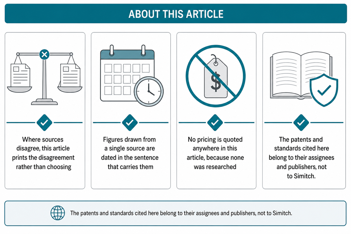
Where sources disagree, this article prints the disagreement rather than choosing: the spot-weld count per body and the ultra-large press tonnage range are both published in more than one incompatible form, and both are shown as spreads with their sources named. Figures drawn from a single source are dated in the sentence that carries them, including the 1995 Volvo functional-geometry targets and the 2013 framing-activity cycle band. Two figures (the mega-casting scrap expectation and the body shop cycle-time fall reported with it) come from indexed quotations in one interview study whose full text could not be retrieved, and are labelled as such. No pricing is quoted anywhere in this article, because none was researched. The patents and standards cited here belong to their assignees and publishers, not to Simitch. No certification, conformity-assessment or standards-compliance claim is made anywhere in this article about Simitch equipment; the conformity route for any given cell is a contractual question to settle in writing before an order.
References & Sources
- Ceglarek and Shi, dimensional variation reduction in autobody assembly · Georgia Institute of Technology
- Al-Zaher, ElMaraghy and Pasek, design of reconfigurable automotive framing systems, 2013 · Journal of Manufacturing Systems
- Stellantis increases efficiency of body-in-white assembly · ASSEMBLY Magazine
- Sheet metal formability and springback measurement programme · National Institute of Standards and Technology
- High precision car body manufacturing, SAE 950573, 1995 · SAE International
- Nagy-Sochacki, sheet metal joining and assembly variation, 2016 · Australian National University
- Review of resistance spot welding in automotive applications, 2022 · Materials Today: Proceedings
- Donders et al., effect of spot weld failure on body dynamic behaviour (archived copy) · Sound & Vibration
- ISO 18278-1:2022, resistance welding weldability assessment · International Organization for Standardization
- Mori et al., comparison of clinching and self-pierce riveting, 2021 · International Journal of Advanced Manufacturing Technology
- Nondestructive evaluation of resistance spot welded aluminium-steel joints · Oak Ridge National Laboratory
- Mechanical joining of advanced high-strength steels · WorldAutoSteel, AHSS Insights
- Regulation (EU) 2023/1230 on machinery · Publications Office of the European Union
- Corrigendum to Regulation (EU) 2023/1230, OJ L 169, 4 July 2023 · Publications Office of the European Union
- ISO 10218-2:2025, robotics safety requirements for industrial robot applications and robot cells · International Organization for Standardization (plain-language explainer: ANSI Blog)
- Gigacasting: the next big idea in automotive manufacturing, December 2025 · ASSEMBLY Magazine
- Gigacasting versus sheet-metal body-in-white manufacturing, July 2026 · Journal of Manufacturing and Materials Processing
- Interview study on mega-casting adoption in vehicle production, 2024 · Journal of Manufacturing Processes
- Dimensional quality control in compliant sheet metal assembly · PubMed Central, National Library of Medicine
- Li et al., assembly variation modelling for automotive bodies, 2020 · Chinese Journal of Mechanical Engineering
![Hot-Melt Connection Molds & Equipment Guide [2026]](https://simitch.com/wp-content/uploads/2026/09/hot-melt-connection-molds-equipment-guide-featured-768x512.png)