Get in touch with Suzhou Simitch Machinery Co., Ltd Company

Sheet metal fastening methods are the ways in which thin metal parts are joined together to form an assembly. The main methods are screws, bolts, rivets, self-clinching hardware, blind rivet nuts, sheet-to-sheet clinching, welding and adhesive bonding. Begin with the joint’s function. Will it need to open for service? What surfaces can the tooling reach? What loads and environmental conditions will it need to withstand?
This guide uses a fastening shortlist for the assembly of panels, ducts and enclosures. For the broader qualification process of the mechanical hardware, please see our sheet metal fastening production guide. In sheet metal assembly, a removable enclosure cover, a duct flange and a permanent appliance bracket can be made from the same base metal, but require different joining techniques. Choosing by fastener price alone may also overlook the mounting hole, tooling, the sequence of finishing and later repair. The table below represents such choices for complete assembly.
Key takeaway
Choose the joint function and assembly sequence before choosing the hardware. A permanently installed insert can support a removable cover; a blind fastener still needs room for its tool and its formed backside.
What Are the Main Sheet Metal Fastening Methods?
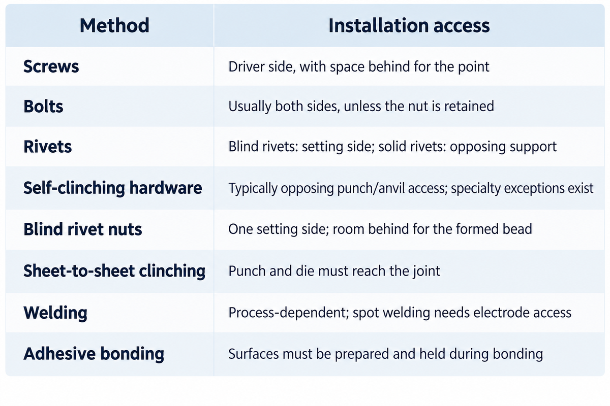
Eight groups describe the main sheet metal fastening methods to be considered for panels, ducts and enclosures. They include mechanical fasteners and other methods that join sheets without separate fasteners. Access means access during installation; removability describes the completed mating joint. Evaluate load capacity and sealing against the particular sheet stack and assembly.
| Method | Installation access | Later removal | Main selection constraint |
|---|---|---|---|
| Sheet-metal screws | Driver side, with space behind for the point | Yes; repeated use depends on the thread system | Sheet engagement, hole and tightening control |
| Bolts and nuts | Usually both sides, unless the nut is retained | Yes | Nut access and load distribution into the sheet |
| Rivets | Blind rivets: setting side; solid rivets: opposing support | Normally requires destroying the rivet | Rivet type, grip range and installation clearance |
| Self-clinching hardware | Typically opposing punch/anvil access; specialty exceptions exist | Screw-attached part can be removed; insert stays | Specified hole, sheet thickness/hardness and press access |
| Blind rivet nuts | One setting side; room behind for the formed bead | Mating screw can be removed; insert stays | Grip, hole geometry, setting and antirotation |
| Sheet-to-sheet clinching | Punch and die must reach the joint | Permanent interlock | Formability, stack order, joint geometry and tool reach |
| Welding | Process-dependent; spot welding needs electrode access | Permanent joint | Material compatibility, heat input, distortion and finish |
| Adhesive bonding | Surfaces must be prepared and held during bonding | Usually not intended for routine disassembly | Surface preparation, joint gap, cure and exposure |
When comparing methods for sheet metal parts, treat this as a selection comparison, not a ranking of strength. Fastener type alone doesn’t explain how the load is transferred to the sheet. Different joint configurations can transfer that load differently. Likewise, a bolt can be removable while the nut or insert carrying its thread remains permanently attached. Those distinctions are far more relevant than calling every threaded connection “temporary.”
For thermal and bonded alternatives, the wider comparison of sheet metal joining methods explains their process differences.
Choose the Joint Before You Choose the Fastener
Choose a method of joining taking into consideration the material stack, load path, access and service requirements. Record the grade and material thickness of each layer, coating and previous forming operations. Based on the above, decide if the connection is required to carry shear, resist opening, or withstand repeated removal during service and if there are any seal or electrical-bonding requirements. This turns fastener selection into a specification.
What is the best way to secure something to sheet metal?
For a serviceable attachment, a threaded connection would be appropriate. For a permanent attachment, riveting, clinching, welding and bonding should be considered against the available access and joint requirements. Thin sheet may need an insert, captive nut or other designed thread support rather than a screw driven directly into it. The choice of fastener depends upon the completed joint, not upon the nominal strength of the component.
Write down where a person or machine can hold the nut, support an anvil and approach the joint. Bends, ribs and adjoining elements should be included. Moisture, finish and the interface of fastener to panel should be considered when joining dissimilar materials; assess corrosion in the intended environment as well as mechanical compatibility. Dissimilar metals don’t become compatible simply because a joining process avoids heat.
Screws, Rivets and Inserts: What Can Be Removed?
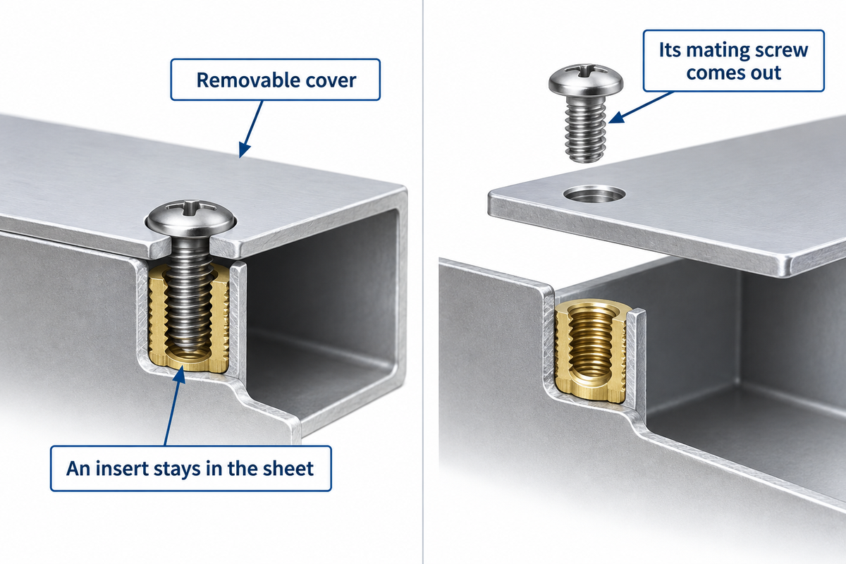
Screws and bolts support disassembly, while conventional riveted joints normally require destructive fastener removal. Bolted joints need access to hold the nut unless it is retained. An insert stays in the sheet while its mating screw comes out. For panels that tend to open repeatedly, consider both the type of reusable thread and the way its supporting hardware resists rotation or movement in the parent material.
Self-tapping screws form or cut mating threads in a prepared hole. Some self-drilling variants also form the hole if they have the capacity to drill it. Neither description provides a universal pilot hole or allowable tightening torque. Use the selected screw’s requirements for the actual metal sheets, including the thickness being engaged and clearance behind the joint.
Rivets also require another distinction. Blind rivets can be installed without a bucking tool behind the sheet; solid rivets require suitable opposing support during installation. Choose the rivet’s grip range against the joint stack and consider its installed shape. Replacing screws with rivets also alters the service operation: A technician may have to drill out hardware and control the debris.
When should I use inserts instead of direct screw fixings?
Consider inserts when the sheet cannot provide the required thread engagement or when repeated removal needs a more durable threaded attachment. The insert still requires a retention mechanism. Self-clinching hardware relies on the surrounding sheet flowing into its retaining profile; a blind rivet nut forms a bead behind the sheet. These installation methods impose different hole, material, and access requirements.
A blind rivet nut wouldn’t be a drop-in replacement based on the size of the threads. Consider mounting-hole dimensions, head projection, grip range, backside clearance, and the setting tool. Specify screw-tightening limits separately from fastener insertion settings. Antirotation can be important to ensure that an insert is fixed in position during later assembly and service.
Clinching vs Self-Clinching Hardware
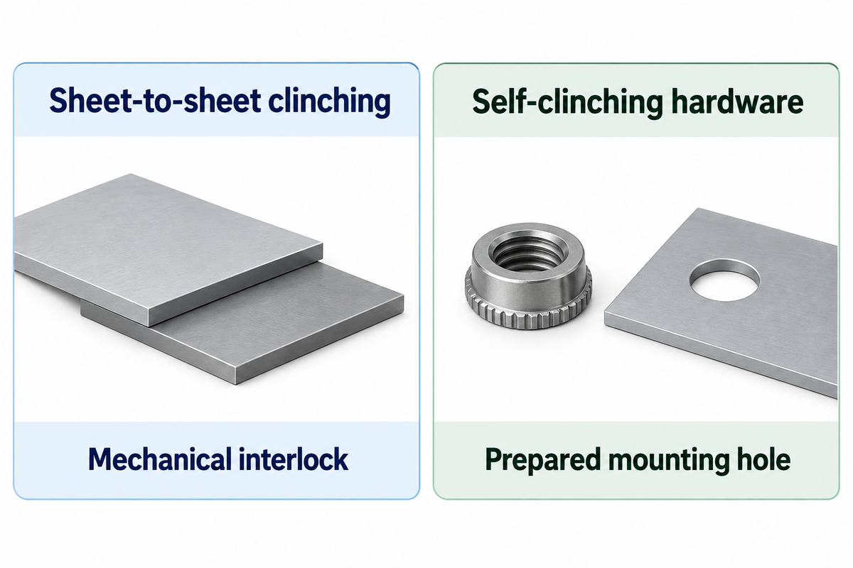
Sheet-to-sheet clinching forms a mechanical interlock in overlapping sheets without adding a separate fastener. Self-clinching hardware installs a nut, stud or standoff into a prepared mounting hole. Both use material deformation, but they produce different joint functions. The first type of joint produces a joint between the sheets themselves. The second type of joint produces a retained attachment of another part.
In sheet clinching, the punch and die deform the stack into a local interlock without additional fasteners. Material must flow without an unacceptable crack or a weak neck. To achieve that, base materials, stack order and the state of the sheet are important. Self-piercing riveting is another mechanical joining process: it adds a rivet and isn’t truly fastener-free clinching.
What installation equipment do I need for self-clinching fasteners?
Conventional self-clinching hardware uses a parallel-acting press with specified punch and anvil tooling. The tooling inserts the hardware in an appropriate sheet and hole. Installation force is product- and material-dependent; a generic press rating does not establish that the tooling can reach the joint or that the hardware will retain properly. Special one-sided installation options also exist, thus verify the design selected rather than assuming generically.
History of the sheet needs to be evaluated along with access. Steinfelder and colleagues’ 2022 clinching study discussed previous material straining, sheet configurations and other process variables. The main lesson was to evaluate representative condition of the production material. Even aluminium sheets similar in nature require their production conditions to be defined. A flat, unstrained region of a sheet coupon isn’t the same as a joint region that has already been formed.
The aluminum joining guide provides a material-focused comparison for aluminium parts. Keep the grade, condition and joint geometry tied to the proposed assembly trial.
Match the Method to Panels, Ducts and Enclosures
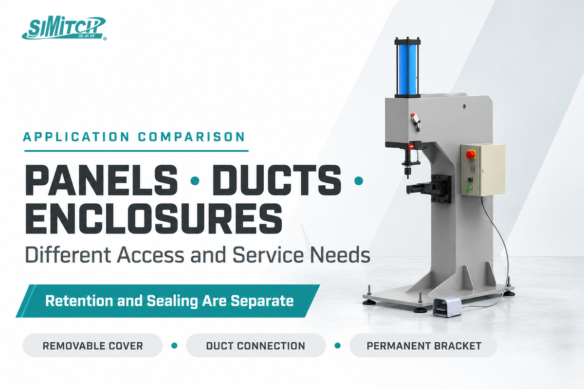
The variations in sheet metal applications require different access and manufacturability conditions. A cover requires accessible release points; a duct connection requires retention with the proper sealing arrangement; a permanent bracket requires a qualified load path. The examples that follow shortlist assembly methods; they show decisions rather than customer trials or universal equipment capabilities.
A cover that opens for routine service
For a removable enclosure cover, compare threaded fasteners with retained nuts or inserts. Install press-in hardware while its tooling can reach the mounting area, confirm that the later screw approach remains clear, then check cover alignment and the allowed tightening procedure. A permanent rivet through the cover would change the repair plan, even if riveting simplified initial assembly.
Where maintenance frequency is high, the service team should try the intended opening and closing sequence on an assembled sample. Also check if service hardware is loose or interfering with the seal; this exercise tests usability and does not replace mechanical qualification.
A galvanized duct connection
For the mechanical connection of a galvanized duct flange, determine the access conditions and sealing conditions separately. A screw or rivet route may suit the part’s geometry; clinching may suit a formable, reachable overlap. The HVAC clinching discussion in ACHR News shows a similar approach, but its author is a clinching supplier and the examples used to illustrate the approach should be application specific.
The US Department of Energy’s Residential duct-sealing job aid illustrates mechanical fastening as distinct from sealing. It depicts various functions; it isn’t a sample of an industrial duct design specification. Mechanical retention doesn’t establish a leak-proof joint. Select the seal, gasket or other sealing means as per the actual requirement of ducts.
A permanent bracket inside an enclosure
For a bracket that will stay attached, compare a clinched overlap, a qualified welded joint or suitable mechanical fastening. With any welding method, include heat input, possible distortion and restoring the surface finish in the route. Spot welding and other welding processes need different access arrangements. Adhesive bonding includes surface preparation, bond-gap control and curing; it may distribute load, but it isn’t automatically suitable for every dissimilar material or exposure.
Don’t presume an intact coating indicates corrosion resistance. Likewise, an adhesive layer, which helps to isolate dissimilar metals, may adversely affect an electrical path that the design of the enclosure may require. Indicate that path intentionally.
Plan Access Before the Enclosure Is Closed
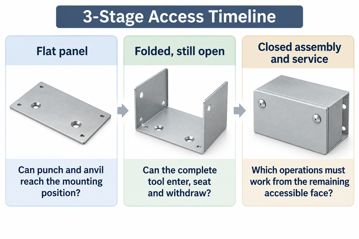
Analyze tool access independently during installation, final assembly and service. A fastener may fit the flat blank, but, after the flange is bent or an internal assembly is added, may become unreachable. The 3-Stage Access Timeline below shows how to identify the last usable access point. It’s a tooling planning aid and shouldn’t be substituted for a tooling trial.
3-Stage Access Timeline
| Assembly stage | Access decision | What to preserve |
|---|---|---|
| Flat panel | Can punch and anvil reach the mounting position? | Hole quality, press support and a workable forming sequence |
| Folded, still open | Can the complete tool enter, seat and withdraw? | Die landing, throat reach, part support and hardware clearance |
| Closed assembly and service | Which operations must work from the remaining accessible face? | Driver access, insert bead space, screw clearance and a removal route |
The timeline accounts for constraints and assembly restrictions. When installing a proposed rivet-nut retrofit, check what’s on the hidden side before drilling or setting anything. A blind installation creates a formed feature behind the sheet. Be sure to add chip control to your work instruction to protect internal features.
Record when a joint region is formed. If a trial uses flat material but production joins a preformed region, the trial should reproduce that condition. Keep the upper sheet and lower sheet identified by their punch and die side. Changing their position changes the material flow being evaluated.
Compare the Cost per Accepted Assembly
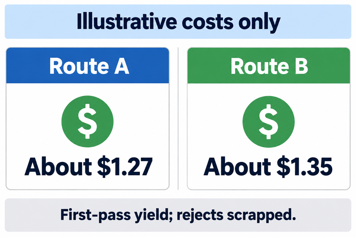
Compare routes using the full cost of making an accepted assembly with the same production volume and acceptance definition. Include added hardware, complete labor time and process costs. A fast forming stroke does not measure loading, locating, inspection and unloading. Yield also changes the denominator: Money spent on rejected assemblies is part of the total cost of the batch and shouldn’t be excluded.
“Yielded cost is defined as cost divided by yield”
Daniel Becker and Peter Sandborn, University of Maryland CALCE research abstract, 2001
For a simple comparison, assume every first-pass reject is scrapped, with no rework recovery or scrap credit. Then divide cost per started assembly by first-pass yield expressed as a fraction. ASQ’s first-pass-yield definition excludes units that need rerunning, retesting or offline repair. A process that recovers rejects through rework needs a fuller cost model.
| Assumed input | Route A | Route B |
|---|---|---|
| Hardware per started assembly | $0.30 | $0.08 |
| Complete direct-labor time | 95 seconds | 115 seconds |
| Assumed loaded labor rate | $30/hour | $30/hour |
| Other allocated cost per started assembly | $0.15 | $0.30 |
| First-pass yield; rejects scrapped | 98% | 99% |
| Calculated cost per accepted assembly | About $1.27 | About $1.35 |
Route A: ($0.30 + 95 ÷ 3,600 × $30 + $0.15) ÷ 0.98 = about $1.27. Route B: ($0.08 + 115 ÷ 3,600 × $30 + $0.30) ÷ 0.99 = about $1.35. These invented inputs demonstrate the arithmetic; they aren’t supplier prices, measured cycle times or predicted plant results.
Use the calculator with your own cost per started assembly and accepted fraction. Ensure all figures are expressed in a single currency and the same batch boundary is applied to both routes.
Cost per accepted assembly
For one batch and cost boundary, divide cost per started assembly by the accepted fraction.
Cost per accepted assembly
currency units
Use one currency and cost boundary. First-pass rejected assemblies are scrapped, with no rework recovery or scrap credit. Enter measured inputs; defaults are illustrative, not supplier prices or predicted performance.
Use one currency and cost boundary. First-pass rejected assemblies are scrapped, with no rework recovery or scrap credit. Enter measured inputs; defaults are illustrative, not supplier prices or predicted performance.
Enter every value to see the result.
This entry is ambiguous. Use a comma only as the decimal mark, for example 1,5, and do not type thousands separators.
Find the Time Outside the Setting Stroke
Use this qualitative hidden bottleneck map to assign observations before comparing equipment. It identifies time to measure; it doesn’t claim which operation limits your line.
| Cycle segment | What to observe | Who checks it |
|---|---|---|
| Load and locate | Handling, orientation, locating and clamping time | Production: repeat with the actual part mix |
| Set or form | Tool approach, joining stroke and withdrawal time | Process engineering: distinguish stroke time from complete cycle time |
| Inspect and unload | Acceptance checks, sorting, unloading and rejected-part handling | Quality and finance: align accepted output with the cost boundary |
Before comparing quotations, production should measure complete assembly time, procurement should align the included hardware and tooling, and quality should define an accepted part. Finance can then check setup allocation and whether rejects are scrapped or recovered. If loading rather than setting is the bottleneck, reducing setting time alone may have little effect on output.
Check Joint Performance Beyond Pull-Out Strength
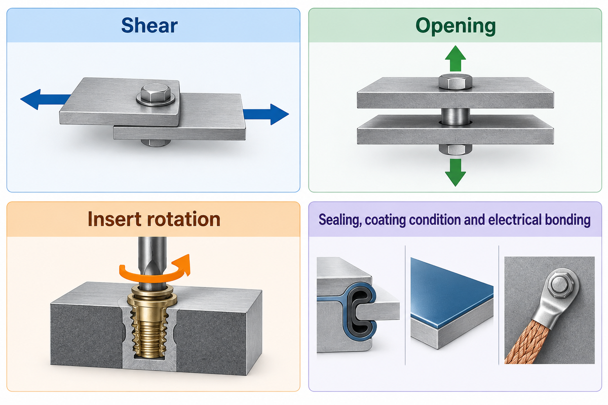
Instead, test joint strength against service loads and functional requirements. Different modes of failure such as shearing, opening, peeling and insert rotation describe various behaviors. The test should reproduce the relevant material, stack, geometry and loading direction, then record the failure mode. Sealing, coating condition and electrical bonding need their own acceptance checks when the application requires them.
ISO 12996:2013 covers specimen dimensions and tensile-shear testing of single mechanical joints, within its stated scope. ISO 16237:2015 addresses cross-tension testing. Both public scopes specify individual sheet thickness up to 4.5 mm and exclude civil-engineering applications such as metal buildings and steel construction. Neither is an enclosure ingress-protection or electrical-bonding certification.
A tensile-shear result therefore can’t be relabeled as resistance to opening the sheets. For threaded hardware, distinguish fastener spin or torque-out, movement out of the sheets, thread damage and failure of the mating screw. They’re different endpoints. Record which component failed rather than assigning the first observed failure load to every component of the joint.
Useful acceptance evidence
- Production-condition material and stack order
- Defined loading direction and failure endpoint
- Separate functional checks where required
Shortcuts to avoid
- Qualifying a formed part from an unrelated flat coupon
- Using torque-out as a substitute for axial strength
- Calling a sealed fastener a waterproof assembly
A strong joint can still fail a sealing or finish requirement. A cold-formed joint avoids welding heat, but deformation or tooling contact can still affect a coating. Examine the joint region and evaluate joint integrity under the required exposure rather than assuming that no heat means no finish damage.
When Is a Clinching Sample Trial Worthwhile?
A clinching sample trial is worthwhile when the proposed permanent overlap is formable, accessible to the tool and compatible with the required joint function; send representative production material and part geometry before choosing equipment. The sample trial evaluates usable joints and access, and tests the part’s performance against its functional requirements.
Provide each sheet’s grade, thickness and coating. Note the previous forming, indicate the punch side or die side, and show bends, joints and overlap and reach restrictions on the part drawing. Also indicate the part mix, the desired total complete-cycle time, and the acceptance criteria. A material coupon test can be used to evaluate the material stack and formability; a complete part test can be used to evaluate whether the tool can enter, form the joint and withdraw.
SIMITCH offers clinching equipment for the joining of automotive components, appliances and HVAC assemblies. Its clinching machines and application assessments page discusses the equipment once the joint requirements have been defined. If the trial rules clinching out, retain the alternative joining method that meets the part’s requirements.
Frequently Asked Questions
What types of fasteners are commonly used in sheet metal?
Screws, bolts, rivets and retained threaded hardware cover the main hardware choices.
Retained hardware includes self-clinching nuts, studs and standoffs, plus blind rivet nuts and other designed attachment systems. Choose the family according to sheet engagement, tool access and service requirements. Keep hardware separate from processes such as welding, adhesive bonding and sheet-to-sheet clinching. Those processes can join sheet metal parts without providing the same removable threaded attachment.
What is the strongest type of fastener?
Choose the fastener that passes the specified joint-load test; no type is universally strongest.
A high-strength fastener can still pull through, spin in or damage a thin sheet. Compare the selected fastener with the sheet grade, thickness, edge distances and joint geometry, then test the relevant load direction. A result from one material stack or test fixture doesn’t establish the capacity of a different assembly. Specify the required failure endpoint before comparing ratings.
Can I use the same fastener for prototype and production?
Yes, if it meets the production material, process and acceptance requirements.
The right fastener for production must meet the production requirements, even if it worked in a prototype. Confirm the production sheet condition, coating, hole-making process, installation equipment and access before retaining the specification. Production also adds feeding, handling, inspection and changeover requirements. If the prototype used a different insert or a hand-set process, document the difference and qualify the intended production route rather than assuming the results transfer.
Can clinching join sheets without an added fastener?
Sheet-to-sheet clinching can form an interlock without a separate rivet or screw.
That differs from self-clinching hardware, where a separate nut, stud or standoff is installed in the sheet. Both need a suitable material and joint design. The word clinching alone doesn’t identify the attachment function.
How do I prevent fasteners from loosening under vibration?
Design and validate retention for the actual joint and vibration conditions.
Start with the load path, intended clamp condition and the selected fastener’s installation requirements. For a threaded insert, distinguish a screw backing out from the entire insert rotating in the sheet. Those problems need different remedies. Suitable locking features or retention products may form part of the design, but a generic washer or adhesive recommendation isn’t a universal fix. Check material compatibility, service temperature and the planned removal procedure. Then assess the assembled joint under representative conditions. If maintenance requires repeated opening, include those cycles in the validation plan rather than testing only a newly assembled connection.
Does a closed-end rivet make an enclosure waterproof?
No. A closed-end rivet alone does not make the complete enclosure waterproof.
The seam, fastener-to-sheet interface, openings and any gasket still affect leakage. Sealed component variants address particular leakage paths. Evaluate the complete enclosure against its specified ingress or leak requirement, including the installed joint condition.
How do you fasten sheet metal?
Define the joint requirements, prepare the specified geometry, install the selected connection and verify it.
Begin with the material stack and decide which surfaces remain accessible during installation and service. Select a method that suits the load path, environment and removal requirement. Follow the chosen hardware or process requirements for holes, edge distances, tooling and setting; don’t borrow a dimension or torque from a different fastener family. Join representative material in its production condition and inspect the result. For a removable connection, check the mating screw and service access as well as insert retention. For a permanent joint, verify the relevant load direction and failure behavior. Finally, check sealing, coating or electrical continuity separately wherever the product specification requires them. Record that accepted condition so later changes in material, tooling or process sequence can be assessed against it.
References & Sources
- ISO 12996:2013, public scope for tensile-shear testing of mechanical joints
- ISO 16237:2015, public scope for cross-tension testing
- Steinfelder et al., interactions between joint and component properties during clinching, 2022
- US Department of Energy, Seal Ducts With Mastic, residential weatherization job aid, 2024
- Becker and Sandborn, Using Yielded Cost as a Metric for Modeling Manufacturing Processes, public abstract
- ASQ, Quality Glossary, first-pass-yield definition
- ACHR News, A Guide to Sheet Metal Clinching for HVAC Contractors, supplier-authored trade discussion, 2025
- Böhm and Meschut, Single-stage setting of blind rivet nuts without pre-drilling, public research paper