Get in touch with Suzhou Simitch Machinery Co., Ltd Company

Press-fit tooling carries the insertion load, locates the parts, and guides their movement. Determine the contact face, support, alignment and acceptance checks prior to purchase of the press. A wrong load path can’t be corrected with a larger actuator.
Quick Specs: define the tooling package
- Upper tooling: punch, driver or sleeve matched to the loaded surface.
- Lower tooling: locating nest and load-bearing support with a clear release path.
- Guidance: rigid location, a guided pilot or specified compliance.
- Acceptance: approved setup, monitored stroke and finished-joint checks.
Press-fit tooling is the contact and support assembly between a press and its workpiece. Adjust its load path to the fitted component and verify alignment and the final joint with representative parts.
Key takeaways
- Force and distance monitoring is available on manual presses; servo motion control is a separate requirement.
- A locating feature and a load-bearing support can have different jobs.
- Lateral float, angular correction and stiffness require separate specifications.
- Use known-good parts and known defects to test acceptance windows.
Updated October 2026. This guide covers industrial press-fitting of bearings, bushings, pins and connectors.
Press-fit tooling: follow the assembly load path
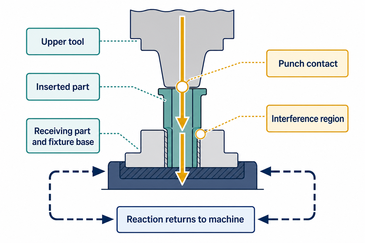
Follow the pressing force through the upper tool, inserted part, and receiving part and fixture base. Each contact must carry its load without damaging adjacent features. The same feature can do both jobs (locating the part and supporting the load), but the drawing should make that decision explicit.
Start with a cross-section through the two parts in their final position. Mark where the punch touches, where interference occurs and where the reaction returns to the machine. The press provides the motion and force; tooling determines how they reach the joint. This distinction prevents a machine quotation from hiding an unfinished fixture design. In metalworking assembly, friction at the fit also makes surface condition a consideration for the trial.
| Decision | Put on the drawing or setup sheet | Check at the trial |
|---|---|---|
| Punch contact | Permitted face, ring or shoulder | Witness marks remain inside the intended land |
| Protected features | Seals, coatings, grooves and electrical contacts | No tool contact or damage |
| Receiving support | Load-bearing region and support profile | Part stays seated under load |
| Location | Datum surfaces and orientation | Repeated loading returns to the same datum |
| Alignment | Axis-setting or compensating mechanism | Entry remains controlled through the stroke |
| Travel | Approach, insertion depth and clearance in mm | No pilot bottoming or tool collision |
| Force | Trial envelope in N or kN and sensor range | Measurement resolves the working process |
| Release | Stripper, ejector and removal direction | Withdrawal leaves the assembly seated |
| Acceptance | Finished dimensions and functional requirements | Independent part results match the release criteria |
NSK’s bearing mounting advice defines the load path as applying the mounting force to the ring with interference. If both rings are tight, the mounting arrangement may need to load both rings simultaneously. Mounting force must not be transmitted by means of a sleeve pressed on the opposite ring through the rolling elements.
For many press-fit parts, the first cost-effective improvement is the correction of a contact or support. Identify that change before replacing the press. A nominal 20 kN machine rating says little about whether a particular thin shoulder is suitable to receive the load.
Punch contact faces that protect the fitted component
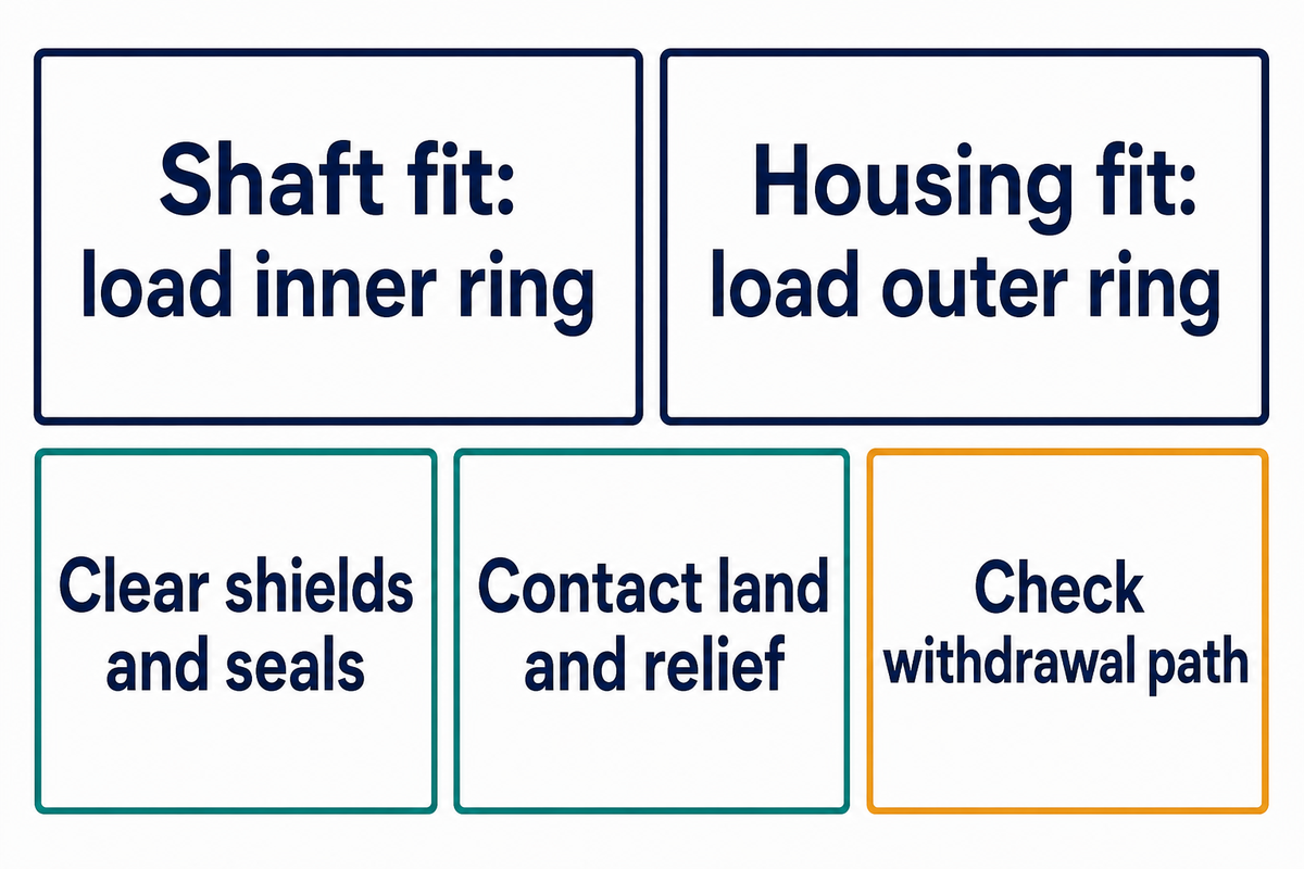
Match the contact face of the tool to the permitted loading surface of the component. A bearing pressed to a shaft usually needs tool contact on the inner ring; a bearing pressed to a housing needs tool contact on the outer ring. Ensure that the tool remains clear of shields and seals and check tight fits against the bearing manufacturer’s mounting method.
What is a punch in press tooling?
A punch is the upper working tool that transmits the press load to the part. In assembly it may be a flat driver, annular sleeve or a shaped insert. Contact, guidance and attachment of the punch determine where the load enters the workpiece and whether the tool can be withdrawn cleanly.
Draw the contact land and the relief together. Relief should clear a protruding shaft, seal or groove throughout the stroke, including the dimensional limits. Precision begins with the loaded geometry; a diameter alone doesn’t describe this interface. Check the specified chamfer and whether the contact land seats evenly. Surface finish, edge condition and parallelism also affect local pressure. Contact-mechanics research by Fabian Forsbach shows how edge geometry changes the stress distribution beneath an idealized punch; it doesn’t supply a universal corner radius for production tools. This research, however, doesn’t provide a general corner radius for production tools.
Drawing scenarios with illustrative dimensions are as follows. Consider a bearing with 20 mm bore and 47 mm outside diameter being fitted on a shaft. An outer-ring driver offers an easy flat surface but routes the load through the rolling elements. The tooling designer provides an annular contact on the inner ring and a central passage for the shaft. Before cutting steel, the designer aligns the driver section over the bearing manufacturer’s drawing, traces the withdrawal path and checks the permitted contact land. At the trial, the bearing is inspected, and its specified running condition is checked. The 20 mm bore identifies the component; it doesn’t determine the driver clearance or the required insertion force.
Specifying the loaded face before stating tool hardness is necessary because a durable punch with the wrong contact geometry can damage the first part. Make the contact insert replaceable in places where its wear is expected, and issue a drawing revision for the replacement.
Support nests for thin-walled housings
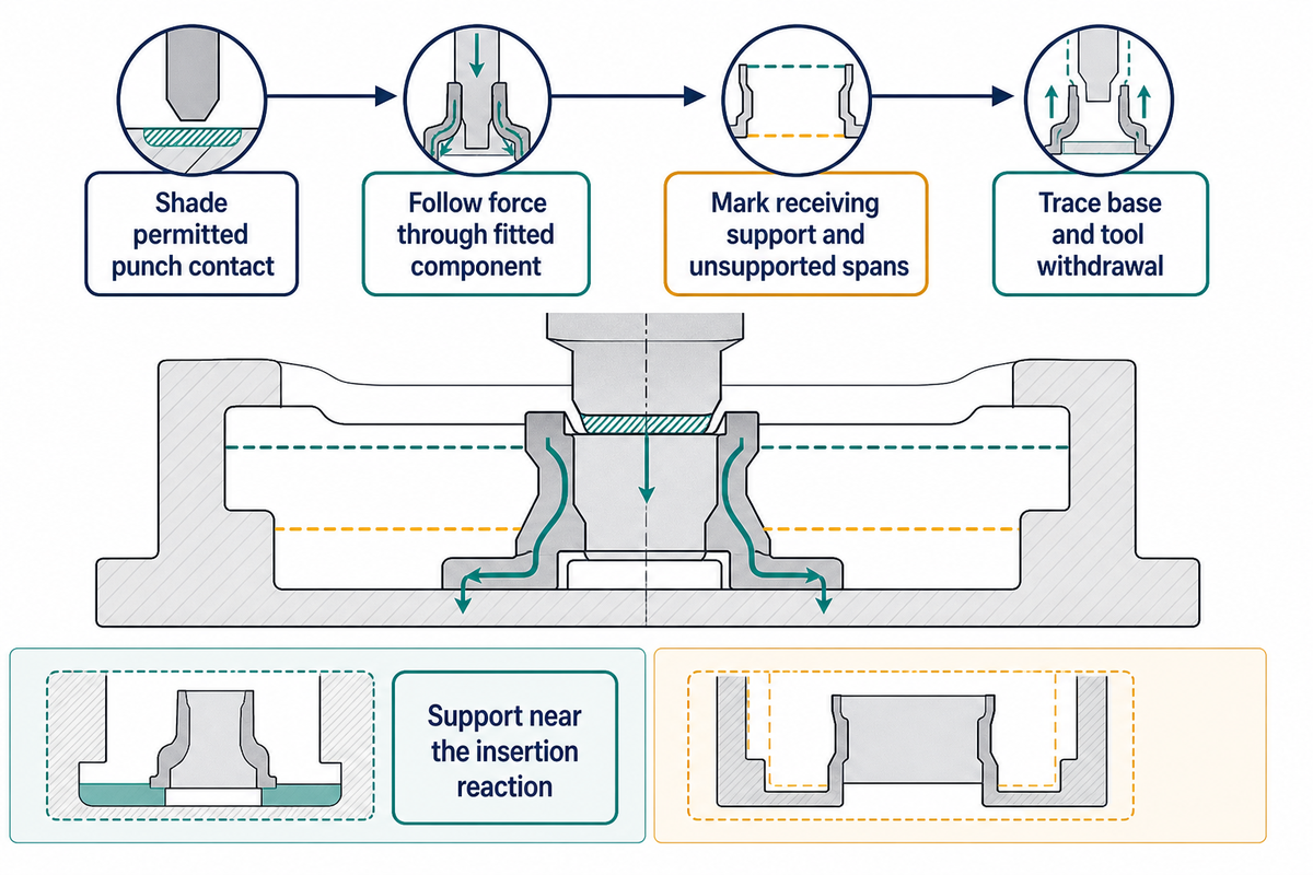
Support a thin-walled housing near the region that receives the insertion reaction while keeping its locating datums stable. A convenient outer flange may not be able to carry the load. Elastic deformation of the support can contribute to measured ram travel. Check the loaded section, local wall thickness and removal clearance, and make sure that the nest supports the assembly through pressing and release.
4-Surface Load-Path Check
Trace the punch contact, fitted component, and the receiving part support and the fixture base to show unintended bending or unsupported load paths.
Imagine a 40 mm bearing entering an aluminum housing with a 3 mm wall and a broad decorative flange. Loading is aided by the flange resting on two blocks. The bearing seat is between the blocks. A closer support ring provides a more direct reaction path. The designer needs to verify the ring can reach the structural land of the housing without touching the bearing and without trapping the assembly. A section view shows the supported region, the no-contact region and the region the ring occupies on exit. Seating should be inspected before loading and the housing measured afterward to verify the bore. A repeatable force trace is useful, but the product release decision also needs the specified bore, face or functional check. The drawing determines the support dimensions.
A Boeing bushing-installation patent, US5363543A, depicts this situation with spaced flanges. The mandrel and anvil arrangement routes the reaction near the loaded bushing instead of transmitting the load over the other flange. The focus is on the path of the reaction; the tool layout isn’t a universal fixture in housing.
Review the section in load order
- Shade the punch’s permitted contact.
- Follow force through the fitted component.
- Mark the receiving support and every unsupported span.
- Continue to the base, then trace tool withdrawal.
A 3 mm wall requires a drawing specific review of support, as opposed to a stock rule that states every 3 mm housing requires the same nest. If the support obstructs release, its geometry or the sequence of opening should be changed before the fixture is approved.
Rigid guidance, floating holders and guided pilots
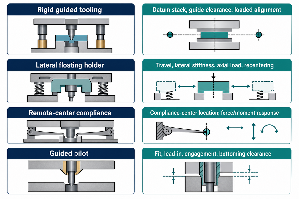
Once the support is secure, choose rigid guidance if the fixture must hold the insertion axis. Choose controlled compliant guidance if the part is free to align its axis of mating and the tooling must account for measured variation. Local alignment is provided by a guided pilot; however, its clearance, path of engagement and exit, and length of engagement must be suitable to the component.
| Arrangement | Useful job | Required evidence |
|---|---|---|
| Rigid guided tooling | Maintain a defined approach axis | Datum stack, guide clearance and loaded alignment |
| Lateral floating holder | Allow specified sideways adjustment | Travel, lateral stiffness, axial load rating and recentering |
| Remote-center compliance | Combine appropriate lateral and angular response | Compliance-center location and force/moment response |
| Guided pilot | Engage a suitable bore before or during insertion | Fit, lead-in, engagement and bottoming clearance |
Descriptions of ATI’s compensators differentiate lateral compliance from remote-center behavior. For a remote-center device, the contact point’s position relative to the compliance center is important. Ciblak and Lipkin’s analysis of remote-center structures shows that the location of the center point is critical and that an inverse relationship exists between linear and angular lateral stiffnesses. Compare the response to the intended force and moment.
What effect does a 0.10 mm lateral setup variation have on the proposed holder under a given axial load? Does it recenter before the next part? Can the component’s lead-in guide the correction? A holder that’s free to move may behave differently when loaded. Record angular variation in degrees.
Rigid guides can bind due to overconstrained conditions. Floating tool holders can allow an unwanted tilt if their response is poorly matched. Misalignment can be fixed with compliance, but only if that compliance is used to correct for the measured condition.
Tooling choices for bearings, bushings, pins and connectors
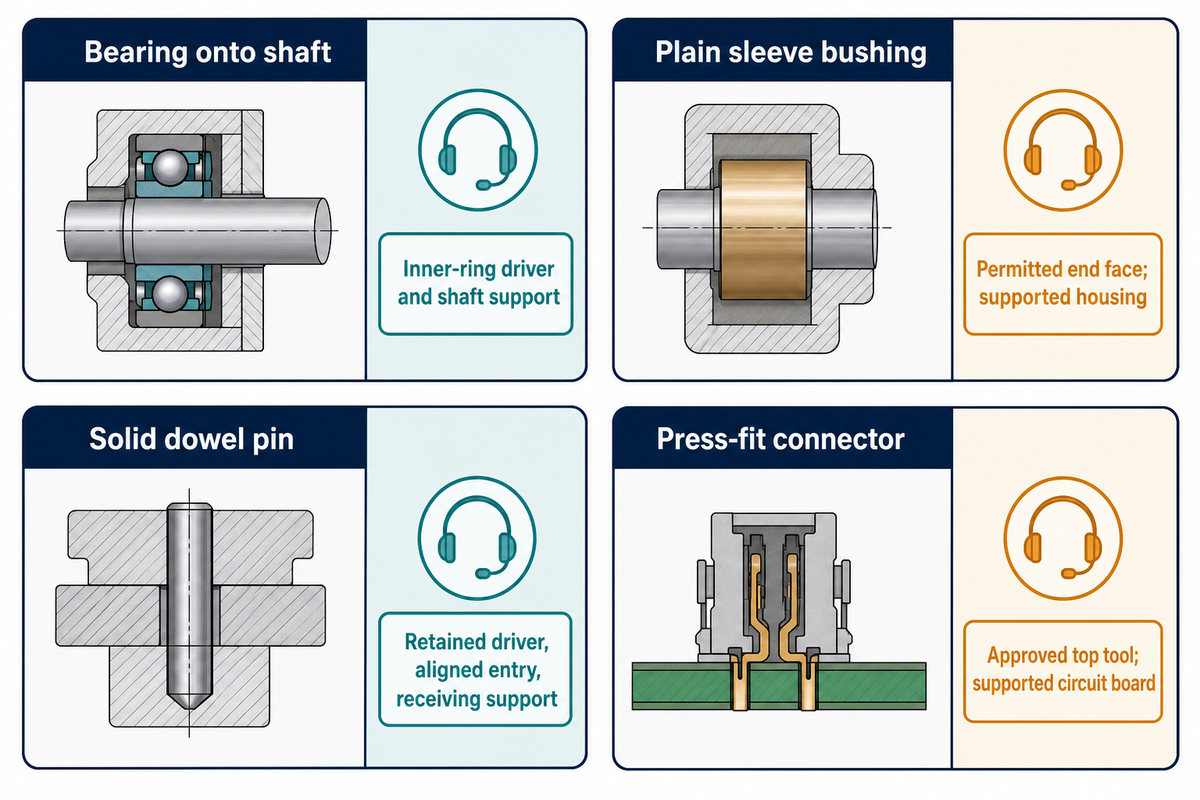
Press-fit technology performs several assembly tasks. Select tooling by the feature being installed and the surface that’s allowed to support the load. Bushings require a controlled entrance and support, and electrical connectors require matched top tools and board support. Similar outside diameters don’t make tools interchangeable.
| Component or task | Contact and support choice | Check after assembly |
|---|---|---|
| Bearing onto shaft | Inner-ring driver and shaft support | Position and specified bearing function |
| Bearing into housing | Outer-ring driver and housing support | Seating and housing condition |
| Both bearing rings tight | Maker-approved simultaneous loading arrangement | Both seats and running condition |
| Plain sleeve bushing | Driver on permitted end face; supported housing | Installed bore and running clearance |
| Flanged bushing | Specified driving face with shoulder clearance | Flange seating and bore condition |
| Solid dowel pin | Retained driver, aligned entry and receiving support | Projection and location |
| Slotted or coiled spring pin | Pin-specific driver and recommended hole preparation | Depth and component condition |
| Press-fit connector | Approved top tool and supported circuit board | Insertion position and specified electrical/mechanical tests |
| Insert into a plastic part | Insert-maker process and local part support | Position, cracking and required retention |
What are the different types of press-fit pins?
Mechanical choices include solid dowel pins and slotted or coiled spring pins. Select the fastener for the joint, and the driver to match the fastener. Electrical press-fit pins may use a compliant contact zone designed for a specified plated hole. Differing pin materials and designs affect force transmission and how a pin is introduced, so the pin design should dictate the driver and hole preparation.
SPIROL’s pin-installation range provides useful examples of scale. Its PM manual machine lists 0.8–4 mm pins and a maximum force of 0.9 kN; PMH lists 0.8–10 mm and 6.7 kN. PR lists 1.3 kN and CR lists 8 kN. The DP drilling-and-pinning machine drills 0.8–6 mm holes and provides insertion force up to 8 kN. These catalog values identify the respective machines. Choose the actual force for assembly from the pin requirements and representative parts, not from the pin diameter alone.
For electronics, IEC 60352-5:2020 addresses solderless press-in connections. A DigiKey support answer for a Harting connector lists separate top-tool and board-support parts. This is why a generic flat plate is a poor starting assumption for a press-fit connector.
Keep the joint design and tooling separate. See our press-fit tolerance limits guide to learn more about dimensional fit. Adhesive-assisted retention, thermal shrink assembly and a weld are other process choices; changing between them requires a new joint design, not just another punch.
Tooling validation before accepting the process
Verify the tooling with representative production parts and a specified finished-joint result. Record setup and Force/Distance, and compare these records to independent dimensional and/or functional checks. Establish acceptance windows with known good parts and challenge them with known defects to evaluate false acceptance and false rejection.
“There’s a difference between process monitoring and process control.”
Manual presses can monitor force-distance curves. Servo systems can use feedback to control motion. State what function the application needs. In September 2026, ASSEMBLY reported EMG monitoring controls for manual and pneumatic presses as an example of this.
Using acceptable components as a reference is described by John Lytle, engineering manager at Promess, in How to Evaluate a Press-Fit Curve. Suppose we extend that work to the variation we should expect with production samples. In a 2015 study by You and colleagues, 18 micropart samples used 12 μm, 13 μm and 14 μm interferences, with approximately matched shape errors and surface roughness. Researchers still noticed curve changes due to surface and form variations. These conditions show the reason a reference is defined for a part population. A calculation can serve as a starting point to guide a trial, but the engineer still relies on measured joint results.
6-Field Tooling Acceptance Record
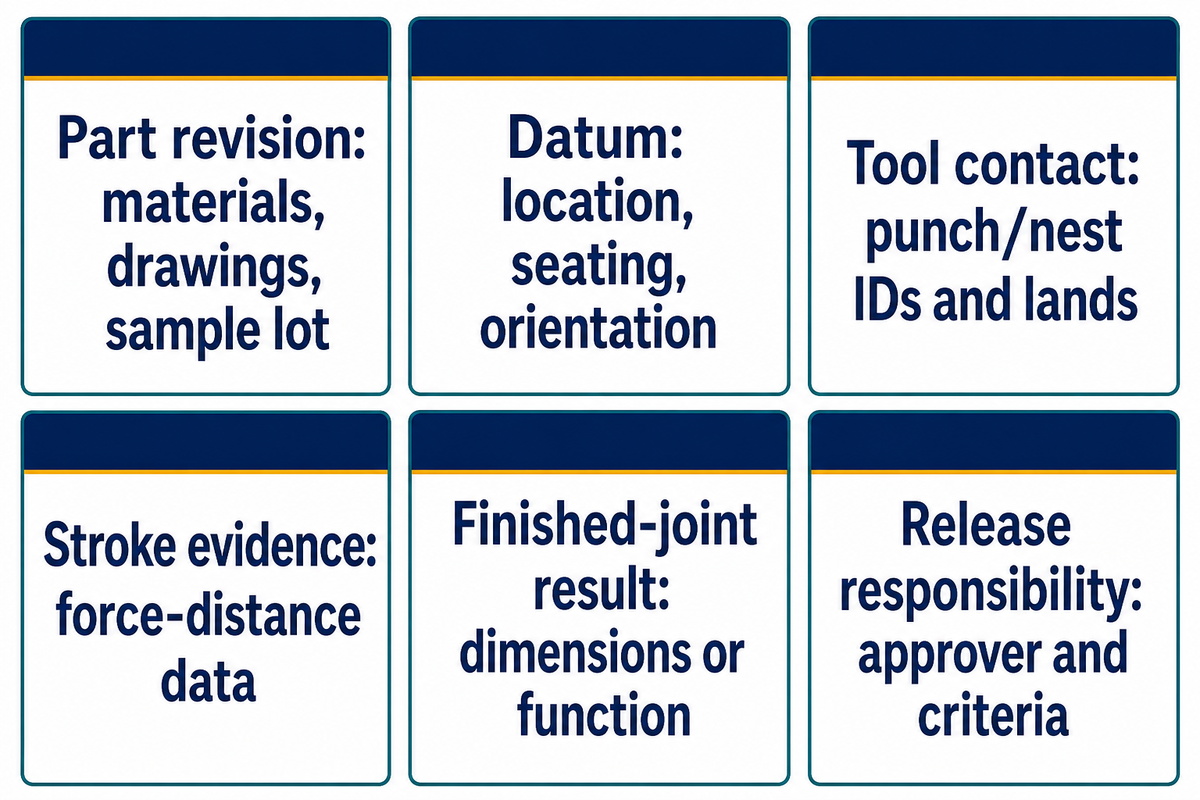
Bind part revision, datum, tool contact, stroke evidence, finished joint result, and release responsibility in one traceable trial record.
| Field | Record |
|---|---|
| Part revision | Part numbers, materials, drawings and sample lot |
| Datum | Locating features, support seating and orientation |
| Tool contact | Punch/nest IDs, revisions, contact lands and reliefs |
| Stroke evidence | Recipe, sensor location, units, force-distance data and classification |
| Finished-joint result | Measured dimensions and specified retention or function |
| Release responsibility | Named approver, acceptance criteria and change triggers |
An illustrative trial for a bushing with a nominal 12 mm insertion depth is considered. A setup record identifies a housing datum and a driver revision. A press records stroke at its ram. An independent measurement verifies the final position of the bushing relative to the housing. The trial includes acceptable assemblies and separate specimens which weren’t correctly seated, and/or have an incorrect component. The team considers each classification versus the measured result as opposed to drawing a tight window around the first attractive curve. If a sensor reports a 12.00 mm stroke and the housing has moved in its nest, the measurement of the part exposes the mismatch. Before release, the owner defines which variations were covered and what change requires another trial.
SIMITCH’s press systems with external sensing support external force and displacement sensors, sampling up to 10 kHz and up to four evaluation windows. Choose the sensor range and location for the working signal. The next step is to validate the force-displacement trace against the joint acceptance criteria.
Custom tooling quotes: define scope and ownership
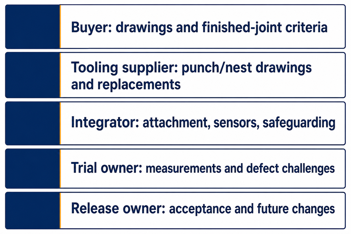
It’s useful to have a customized-tooling quotation to separate design, manufacture, trial work and acceptance responsibilities. Send the supplier part drawings, sample conditions and required finished conditions. Find out what’s included in the price, who controls revisions, inserts and press programs after the first tooling set is delivered.
The acceptance record serves as the technical attachment. ASSEMBLY’s reporting on press selection recommends involving suppliers early in station design and testing production-ready parts. Suppose a tooling package for an automotive program is requested. The buyer needs to state his traceability requirements. The responsibility for fulfilling the remaining requirements can then be assigned as appropriate.
- Buyer: approved component drawings, production variations and finished-joint criteria.
- Tooling supplier: punch/nest drawings, interfaces, materials and replacement-part definitions within the quoted scope.
- Integrator: press attachment, sensor arrangement, safeguarding and station sequence.
- Trial owner: sample identification, measurements, defect challenges and report delivery.
- Release owner: acceptance decision and rules for future changes.
When requesting a quote for an insertion of 12 mm stroke, differentiate the working stroke from the approach distance, and the space required to load and remove the part. List spare guides and wear inserts, and other trial rounds, separately. A lower price for the first offer can hide scope differences that make offers hard to compare.
Discuss the expected force range and component, and the tooling interface with SIMITCH when selecting an integrated press solution. Agree on the supply boundary in the quotation, so the buyer knows which party delivers each tool and test result. The engineering solution should tie these responsibilities to measurable release criteria.
Press integration, changeover and tool maintenance
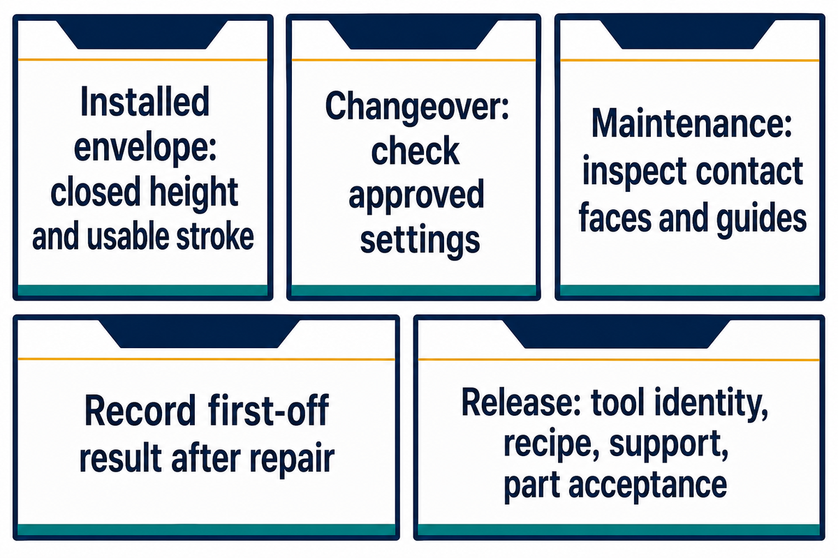
Before placing the complete installed tooling envelope into service, check the attachment of rams and other components, closed height, usable stroke, loading access and release motion. Check the sensor range against the process and identify the fitted tool in the recipe. After a changeover, check the settings against the approved record before releasing production parts. The record also serves as a reference for maintenance personnel for returning tooling into service after repair in the manufacturing industry.
A maximum stroke of 300 mm for a machine doesn’t ensure 300 mm would be available after the tool stack is installed. SIMITCH lists that maximum for its BP series alongside a 10–200 kN force range. Check the selected model, assembly arrangement and available space for the compact nest, actuator movement and ejector. The listed 0.01 mm repeat-positioning value describes the equipment; set the finished-part tolerance through the joint design and measurement plan.
Review guarding and operator access across loading, pressing, jam recovery and maintenance. ISO 12100 provides a machinery risk-assessment framework. Select any more specific press standard by its scope: ISO 16092-1:2017 excludes certain principal fastening operations, including riveting. Its replacement was still a committee draft when checked in October 2026.
Examine contact faces for damage and pickup, guides for wear, and release features for free movement. Damaged mating surfaces can gall; dirt underneath a support can change seating. Record the first off result after replacing a punch insert or repairing a nest. For automation, include identification of tool, and confirmation of part-release in the assembly line handoff requirements.
Release the setup as a package. Tool identity, recipe, support condition and part acceptance belong together. A replacement insert can change contact geometry even when the machine settings stay the same.
Press-fit tooling questions
Always start from the component drawing and required joint result. These answers separate tooling, fit requirements and maintenance decisions, so the quote covers the actual assembly.
What is the best press fit tool?
Choose by the component and the permitted load path.
The best tool matches the component’s permitted contact face, receiving support, alignment method and required finished result. A bearing sleeve, bushing driver and connector insertion tool solve different problems. Start with the component drawing and installation specification, then confirm press compatibility and sample acceptance. Compare suppliers against that same scope rather than choosing by maximum force or apparent versatility alone.
What is the acceptable tolerance for a press fit bushing?
Use the specified bushing and housing requirements.
There’s no single tolerance suitable for every bushing. Use the manufacturer’s housing and installation requirements, then account for material, wall thickness, temperature and the bore condition after pressing. Tooling should respect those requirements. Check the installed internal diameter when the application needs running clearance, and keep that dimension separate from the free-state outside diameter used to define the housing fit.
Why are press fit tools so expensive?
The price can include a complete fixture and trial package.
A custom tooling price may include more than a machined punch. A support nest, guides, wear inserts, sensors, changeover features, sample trials and engineering revisions can all be part of the quotation. Compare the included work and acceptance responsibility before judging price. Ask for replaceable wear parts and repeat-order costs as separate lines, and identify who supplies the approved drawings.
Does press-fit tooling work with a manual press?
Yes, when the press and tooling meet the application.
Manual actuation can suit the required force, alignment and stroke. It still needs controlled contact surfaces, stable support and finished-part checks. Monitoring is also possible on manual equipment; decide separately whether the process requires feedback-controlled motion.
What are press-fit connectors?
Press-fit connectors make specified electrical connections without solder at the pressed interface.
Press-fit connectors use contacts that engage specified holes in a circuit board. Compliant contact zones and plated-hole requirements make them different from ordinary solid dowel pins. Use the connector manufacturer’s approved insertion tooling and board support. Permitted loading surfaces, nearby-component clearance and pin alignment depend on the exact assembly. Electrical reliability follows the defined connection and test requirements; the absence of solder alone doesn’t establish it.
Can floating tooling correct a poorly located part?
Floating tooling can accommodate specified movement after the part is properly supported.
Floating tooling works within its designed motions, stiffness and load capacity. Establish a stable nest and a reliable datum first. Measure the misalignment, then validate the holder’s correction and recentering under the actual insertion load.
When should press-fit tooling be replaced?
Replace or repair it when wear affects an agreed function or check.
Inspect the contact, location, support and release features against the tooling specification. Damage, pickup, guide wear or a failed acceptance check can trigger repair or replacement. A universal stroke count is a poor substitute for those observations. Keep tool identity and first-off results traceable so changes can be investigated. Before a repaired nest or new insert returns to production, complete the checks defined in the approved setup record.
Considering press-fit stations? Send your drawings and sample requests for the desired finished joint result. SIMITCH can address the press system, monitoring functions, and integration for your application.
The two checklists named are editorial methods consisting of cited instructions for mounting and process control. Drawing scenarios are illustrative, and catalog specifications retain the scope stated by their named manufacturer.
References & Sources
- Forsbach: stress beneath axisymmetric contact bodies Frontiers in Mechanical Engineering, 2020.
- US5363543A: Method of aligning two bushings in a bore Boeing patent record, 1994.
- Ciblak and Lipkin: Remote Center of Compliance Structures Journal of Robotic Systems, 2003, public abstract.
- IEC 60352-5:2020 International Electrotechnical Commission, public scope and edition record.
- Common Mistakes With Presses ASSEMBLY, 2022.
- Control Monitors Force and Displacement During Press-Fit Assembly ASSEMBLY, September 2026.
- How to Evaluate a Press-Fit Curve John Lytle, Promess, in ASSEMBLY, 2024.
- You et al.: Prediction of Pressing Quality for Press-Fit Assembly International Journal of Aerospace Engineering, 2015.
- ISO 12100:2010 International Organization for Standardization, public scope.
- ISO 16092-1:2017 International Organization for Standardization, public scope and status.