Get in touch with Suzhou Simitch Machinery Co., Ltd Company

Thin-sheet engineering guide · Updated September 2026
Compare seven joining routes considering material stack, gauge, coating, heat, tool access, joint geometry, service load, visible surface limits, repairability and the proof required to warrant manufacture.
Sheet metal joining methods are processes for connecting thin sheets or formed components, including resistance spot welding, arc or laser welding, brazing and soldering, clinching, riveting, removable fasteners, adhesive bonding, and hybrid combinations. There’s no best choice. The solution is the route that fits the actual sheet stack, can get to the joint, holds up in its service environment, and can be confirmed by data that corresponds to the actual production part.
The most straightforward means of making a poor selection is to evaluate process names before locking in the part definition. A joint that’s strong in one lap-shear coupon may be infeasible to tool in the actual assembly, unacceptable on a show surface, unsafe to weld through a coating, or difficult to separate during repair. Accordingly, this guide employs a constraint-first sequence: define the joint, eliminate impossible routes, evaluate the survivors, then defend the selected route.
This guide provides assistance in making production-related judgments. This isn’t a structural design calculation, legal determination, weld procedure, adhesive recipe, ventilation design, or assessment of machine guarding. Final acceptance criteria will be determined by the respective engineering, quality, EHS, and regulatory teams for the installed application.
For broader process-family economics and supplier-brief questions, see the wider metal joining method selection guide. For hardware catalogs, hole requirements, and removable options, refer to the sheet metal fastening methods guide. Separating these jobs helps this thin-sheet article from duplicating other pages.
Selection unit
The complete sheet stack and local joint
The complete sheet stack and local joint
First gate
Access, geometry, heat, surface, and service constraints
Access, geometry, heat, surface, and service constraints
Evidence rule
Keep each result attached to its specimen and load mode
Keep each result attached to its specimen and load mode
Commercial handoff
Choose equipment only after route feasibility
Choose equipment only after route feasibility
1. Seven Sheet Metal Joining Methods at a Glance
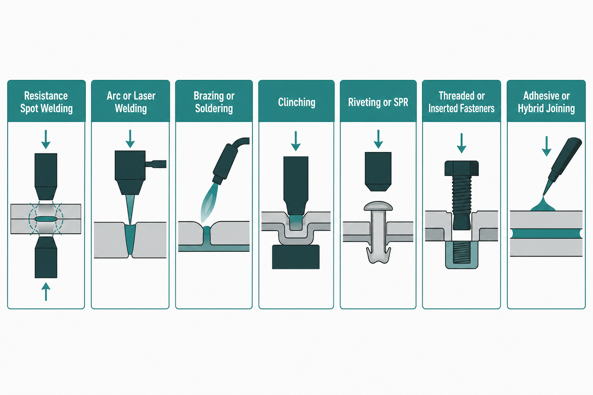
The following seven process-families operate within broad performance boundaries. The purpose of the table is to define the first limit that should be checked to establish a scope. This shouldn’t assign a generic High, Medium, or Low.
Terminology boundary: These joining techniques cover common ways to join sheet metal, from temporary joining and other temporary and permanent hardware choices to permanent joining processes designed for strong joints. With precision sheet metal components and automotive applications, the right joining strategy depends on the layers of sheet metal, the joining materials, and whether engineers must join two metal parts, join dissimilar metals, or temporarily join metal without damaging a visible surface. The objective is to hold the metal together while preserving the required geometry and finish. Thermal joining technology includes MIG and TIG welding (metal inert gas and tungsten inert gas processes), along with welding techniques such as friction stir welding and ultrasonic welding for selected non-ferrous metals. In the automotive industry, techniques for joining thin sheet and joining dissimilar materials, including soldering and brazing, brazed joints, and processes using a metal rod as filler, impose different access, heat, and proof boundaries. These various joining methods frame sheet metal joining decisions, but the right joining method still follows the actual stack and validation plan.
In sheet metal fabrication, joining metal parts is seldom a material-name choice. The same metal sheet can behave differently after forming, coating, or heat treatment, and automotive sheet metal parts can place a joint in peel, crash, fatigue, sealing, and appearance conditions that a flat coupon does not reproduce.
| Route | Heat at joint | Added hardware | Typical access boundary | First proof question |
|---|---|---|---|---|
| Resistance spot welding | Localized resistance heat | No | Two electrodes normally approach opposite sides | Can the actual stack form a stable nugget without unacceptable surface, coating, or interface damage? |
| Arc or laser welding | Fusion heat | Sometimes filler | Tool, shielding, fit-up, and seam access | Can heat input, distortion, penetration, fumes, and finish be controlled on the real geometry? |
| Brazing or soldering | Filler melts; base sheets should not | Filler and often flux | Joint clearance and heating access | Do alloy compatibility, cleanliness, capillary geometry, service temperature, and residue control fit? |
| Clinching | No fusion heat | No | Punch and die on opposite sides | Can the stack form a repeatable interlock and neck without cracks or unacceptable marks? |
| Riveting or SPR | Usually cold | Rivet | Blind rivets may be one-sided; SPR normally needs die-side reaction | Do rivet, stack order, die, protrusion, fatigue, sealing, and corrosion behavior match? |
| Threaded or inserted fasteners | Usually cold | Yes | Hole-making, installation, and service-tool access | Are bearing, pull-out, torque, loosening, edge distance, and inspection acceptable? |
| Adhesive or hybrid joining | Cure-dependent; hybrid route may add heat | Adhesive; sometimes a discrete joint | Bondline application, fixturing, cure, and inspection access | Can preparation, contamination, cure, ageing, repair, and bondline quality be controlled? |
TWI also considers method selection based on assembly, service requirement, time, and cost rather than a single material-strength ranking. That broad context is useful, but a production decision still requires the actual stack and proof plan.
2. Freeze the 8-Input Joint Brief Before Naming a Process
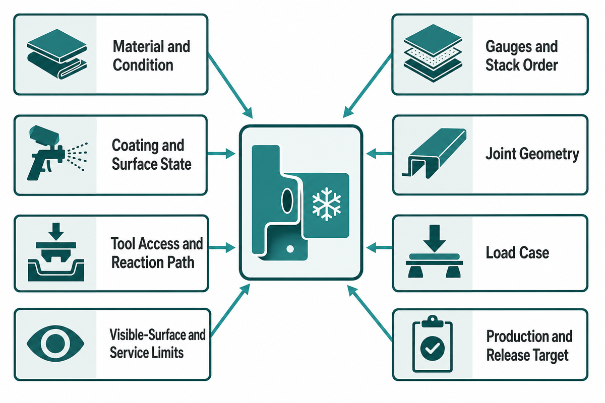
Start a credible comparison with a frozen joint brief. If one of the proposals is based on bare mild steel and another is based on prepainted steel and aluminum, then their process names and costs aren’t comparable. The joined sheet assembly, not an isolated material name, establishes the boundary. Before requesting a recommendation or sample, document these eight inputs:
- Material and condition: alloy or grade, temper, level of strength, hardness, and possibly any material-direction concern.
- Individual gauges and stack order: upper sheet, lower sheet, interlayer, total stack, and tolerance – not total thickness in isolation.
- Coating and surface state: galvanizing, paint, oxide, lubricant, contamination limit, cleaning method, and whether damage is permitted.
- Joint geometry: lap, flange, seam, edge distance, overlap, local curvature, and zone available for a button, weld, rivet, hole, or bondline.
- Tool access and reaction path: approach direction, throat depth, fixture space, electrode or die clearance, and how the part transfers joining force.
- Load case: shear, peel, tension, torque, impact, static or cyclic spectrum, load path, local stiffness, and failure mode and effect.
- Visible-surface and service limits: Allowable marks, protrusion, flushness, leak path, corrosion environment, temperature, repair, removal, and end-of-life separation.
- Production and release target: rate, changeover, traceability, inspection method, challenged conditions, acceptance limits, and revalidation requirements.
The field load needs to go beyond “strong enough.” ISO/TR 12998:2019 defines shear, peel, normal-tension, and combined fatigue loading. The abstract, which is available for public viewing, states that a direct application of fatigue in design can be justified as long as service loading and the local stiffness around the joint are similar to the tested case. For this reason, a flat lap coupon can be taken as evidence of its condition but cannot be deemed sufficient for all formed assemblies.
Do not ask “Which process is strongest?” until the team can answer: strongest under which load mode, in which stack, after which exposure, and with which acceptable failure mode?
3. Thermal Joining: Spot, MIG, TIG, Laser, Brazing, and Soldering
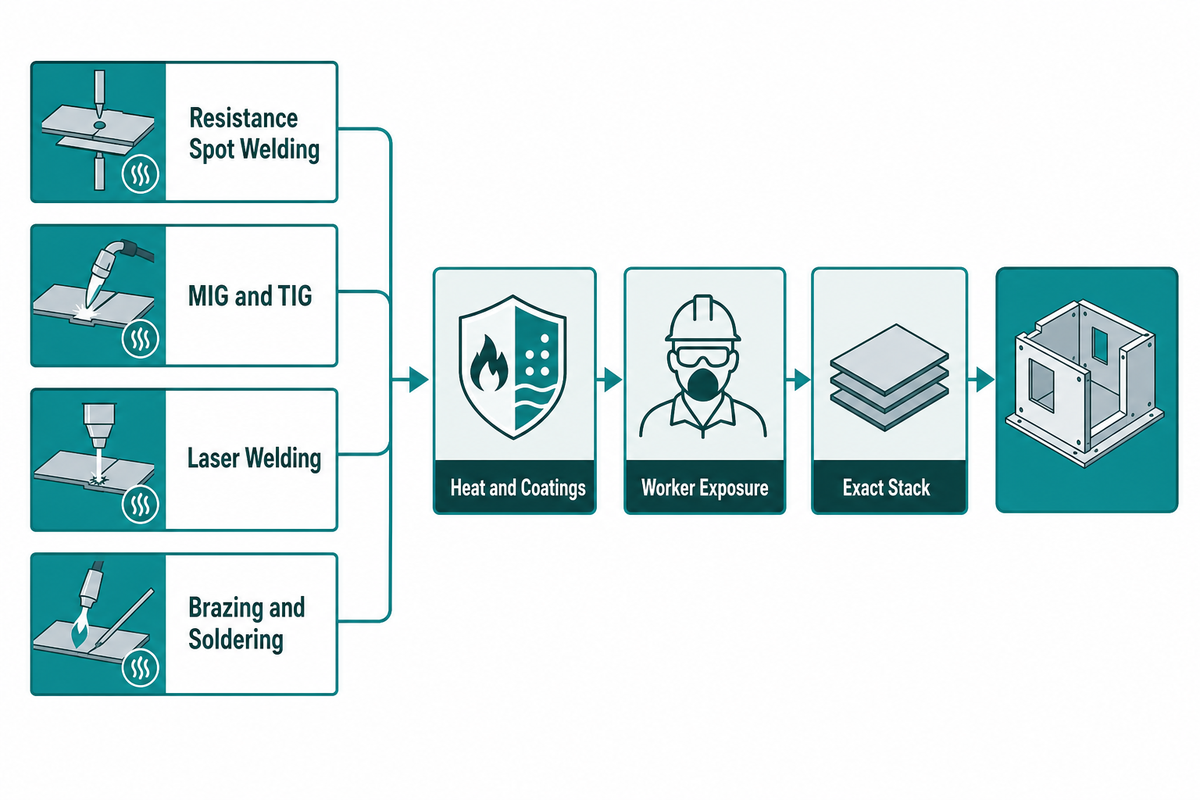
With the joint brief fixed, thermal routes remain valuable for thin sheet, but “uses heat” is too broad to be a decision. Resistance spot welding concentrates current and pressure in overlapping sheets. MIG and TIG produce welded joints with different filler metal and degrees of operator control. Laser welding concentrates energy in a narrow interaction zone, but it has stringent requirements in terms of fit-up, beam access, shielding, and process control. Brazing and soldering melt a filler below the base-metal melting point, and therefore, clearance, wetting, residues, and service temperature become critical. Each welding process requires its own fit-up and control plan.
Heat and coatings are screens, not automatic disqualifiers
Although they have low thermal mass, thin sections are prone to thermal distortion and burning when combinations of heat input, restraint, fit-up, sequence, and travel conditions aren’t optimized. Coatings change electrical contact, wetting, fumes, electrode conditions, surface appearance, and corrosion behavior, but it shouldn’t be concluded that coated sheet is unsuitable for welding. An open study joined galvanized and uncoated steels to aluminum with a resistance-welded insert plus adhesive; it also documented brittle intermetallic, oxide, and process limitations. The conclusion is to test the exact stack; don’t presume one success or failure will apply to all other cases.
Add worker exposure to the route screen
Thermal testing isn’t complete if it evaluates a joint but ignores what the coating releases. Per OSHA, fume fever due to metal is commonly caused by zinc oxide in galvanized steel or zinc-rich paint. For welding type conditions, ventilation and respiratory control are required. Coating identity, process emissions, enclosure, extraction, and EHS review are to be treated as inputs to a production trial. This article can’t recommend the control system specific to a given workplace.
The accepted economics of existing welding equipment shouldn’t compromise surface, coating, access or exposure. For each surviving thermal route, define weld or filler geometry, allowable distortion, surface repair, inspection, destructive-test frequency, electrode or consumable management, and the change that triggers requalification.
4. Cold Mechanical Joining: Clinching, Riveting, SPR, and Fasteners
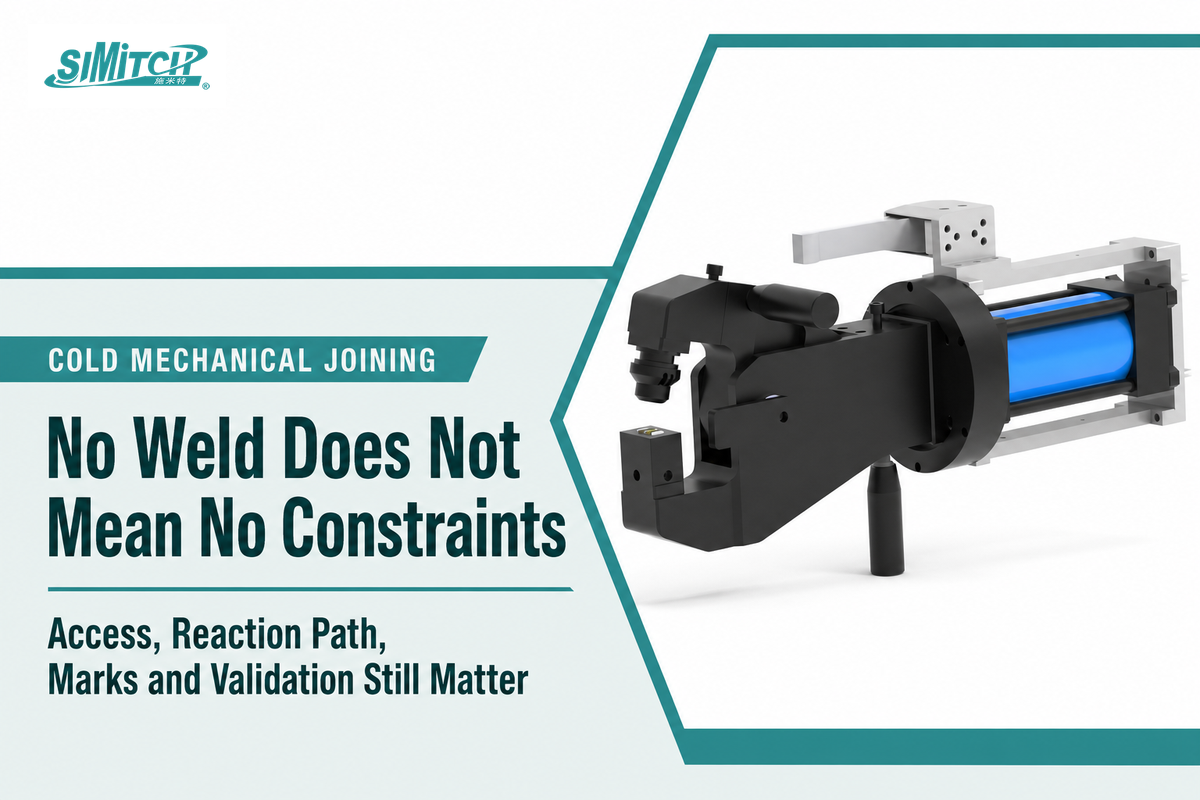
Cold mechanical fastening routes avoid a weld heat-affected zone, but they do not share one access pattern or one failure mode. Clinching plastically forms overlapping sheets into a permanent joint without a separate fastener. Conventional riveting normally uses a preformed hole. Self-piercing riveting drives a rivet through the upper layers and expands it into the lower layer against a die. Blind rivets are installed from one side. Threaded fasteners and inserted nuts add removability or service access, but they also add holes, parts, torque control, loosening risk, and local bearing loads.
Does no-weld mean one-sided access? No. Conventional clinching needs a punch and die on opposite sides, and SPR normally needs a die-side reaction path. A blind fastener is a genuinely different access solution. The peer-reviewed clinching review describes the blank holder, punch, and die and identifies tool geometry, interlock, neck thickness, material ductility, and die-side protrusion as important constraints.
Key takeaway
A no-weld method removes fusion heat; it does not automatically remove die-side access, surface marks, corrosion interfaces, consumables, or application-specific joint testing.
Clinching should be evaluated for a stack trial since the local nature of forming imposes limits on the capabilities of the material. A material that is strong in tension can still crack during severe local forming, while a soft stack can form a button that lacks the required neck or interlock. The order of the stack also matters. For riveting, confirm head-side finish, tail or protrusion, rivet compatibility, hole quality where applicable, corrosion isolation, and inspection. For removable hardware, assess the complete system that provides tightening and service access rather than just the sheet coupon.
Use the self-piercing riveting process validation guide for SPR-specific proof, the industrial riveting equipment page for commercial equipment pathways, and the fastening guide above for hardware-level selection.
5. Adhesive and Hybrid Joining for Thin or Dissimilar Sheets
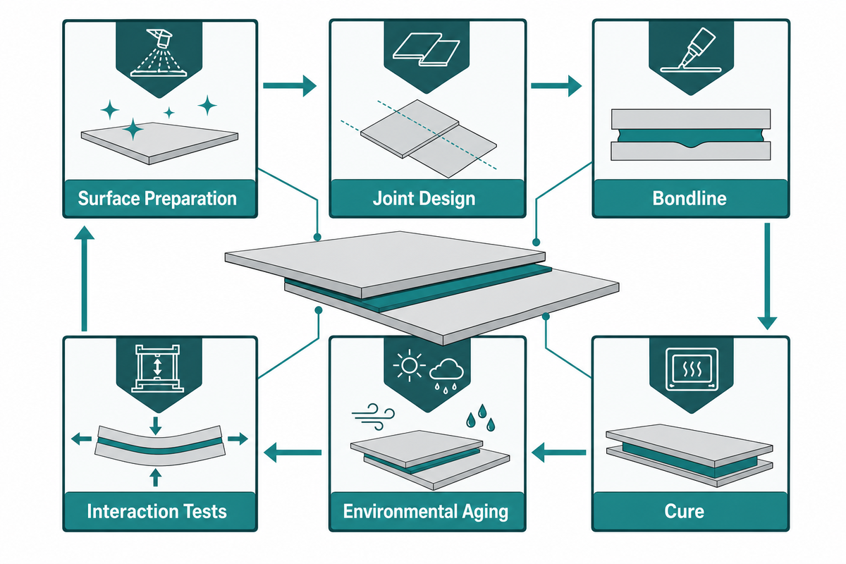
After screening cold mechanical routes, adhesive bonding can spread load across an overlap, add sealing, separate dissimilar metals, and avoid a concentrated heat source. The benefits of bonding introduce other control issues such as material shelf life, environmental aging, contamination, prep and application of surfaces, bondline, fixturing, cure, inspection, and the design and planning for separation or repair.
Outside this cross-method comparison, for material-specific context, the aluminum joining methods guide covers aluminum-related process issues in more detail.
ISO 17212 ties bonding suitability to surface preparation, joint design, function, and service environment. It states that metal-alloy surfaces require material-specific treatments and addresses cleaning, storage, and the evaluation of surface and material durability. Thus, “apply adhesive” is not a well-defined process instruction. Potential users of the technology should be able to name the surface conditions, time limits, applicable checks, evidence of cure, and the environmental stresses of the stack.
Why hybrid results cannot be copied between stacks
In one open 0.8 mm steel and 1.0 mm aluminum experiment, an insert-element resistance spot weld carried about 1.8 kN. Hybrid versions reached about 6 kN with one rubber-based adhesive and roughly 10–12 kN with an epoxy-based adhesive. A separate recent study reported 17.0 kN for its best hybrid configuration versus 0.92 kN for its reference. They show interaction between joining elements, not catalogue ratings. Materials, thicknesses, surface treatment, overlap, adhesive, interlayer, cure, and test geometry all changed the result.
These results are compiled with associated numbers for context and boundary of the original test or standard and shouldn’t be interpreted as recommended design values.
| Evidence type | Reported value | Boundary |
|---|---|---|
| Fatigue guidance | 0.5–6 mm sheet-specimen range | ISO/TR 12998 public scope; not a process capability range |
| AHSS/UHSS note | Generally below 3.0 mm | Context note in ISO/TR 12998, not a universal joining limit |
| Tensile-shear standard scope | Up to 4.5 mm per individual sheet | ISO 12996 specimen/test scope |
| Open hybrid study stack | 0.8 mm steel | Named steel grade and insert-element experiment |
| Open hybrid study stack | 1.0 mm aluminum | EN AW-6082 T6 in the named experiment |
| Insert-element RSW result | About 1.8 kN | Reported test variants, not a spot-weld rating |
| Rubber-adhesive hybrid result | About 6 kN | Same named experiment and adhesive system |
| Epoxy-adhesive hybrid result | About 10–12 kN | Same named experiment and adhesive system |
| Recent interlayer study stack | 1.8 mm extruded aluminum | 6063-T6 material in that study |
| Recent interlayer study stack | 2.2 mm cast aluminum | Cast material branch in that study |
| Recent interlayer study stack | 1.5 mm coated steel | Usibor 1500 AS150 in that study |
| Interlayer-only result | 2.9 kN | Reported maximum tensile-force comparison |
| Best hybrid result | 17.0 kN | Best tested combination, not a transferable promise |
| Reference result | 0.92 kN | Reference extruded aluminum–steel RSW specimen |
For scale, not selection limits, ISO/TR 12998 covers fatigue specimens from 0.5 mm to 6 mm at room temperature and up to 80% relative humidity, while noting AHSS and UHSS are generally below 3.0 mm in this context; ISO 12996 covers individual sheets up to 4.5 mm. The interlayer study separately tested 1.8 mm extruded aluminum, 2.2 mm cast aluminum, and 1.5 mm coated steel, with an interlayer-only result of 2.9 kN.
The separate corrosion study used 1.2 mm aluminum and 1.5 mm galvanized steel and challenged welded specimens in a 3.5% NaCl solution. Its result isn’t a service-life forecast, but it shows why material thickness, interface condition, exposure, and effective joint area must stay attached to any corrosion-strength discussion.
In this hybrid joining system, each element must have an allocated function. The joining elements require testing, so the qualification plan should include interaction tests. A discrete joint can squeeze out adhesive, alter bondline thickness, damage a coating, or create a corrosion path. Structural adhesives need to be designed to strike a balance between high durability and the ease of maintenance and recycling.
6. Let Access and Joint Geometry Eliminate Impossible Routes
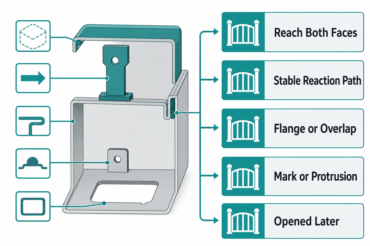
When benchmarking joint strengths, draw the tool approach and reaction path over the real part. A process developed on two flat coupons may fail when used in a return flange, box section, narrow channel, or closed assembly. Use section views as opposed to a top view.
| Question | What it can eliminate | Evidence to request |
|---|---|---|
| Can tools reach both faces at the joint? | Conventional clinching, SPR, and opposed-electrode spot welding when the back face is inaccessible | Section drawing with tool envelopes and assembly sequence |
| Is there a stable reaction path? | Press-based routes where the part or fixture cannot carry joining force without deflection | Fixture concept, force path, deflection review, representative trial |
| Is the flange or overlap large enough? | Routes whose button, nugget, rivet, hole, or bondline conflicts with an edge or bend | Dimensioned local geometry and cut section |
| Can a mark or protrusion remain? | Buttons, rivet tails, heads, weld marks, heat tint, squeeze-out, or visible repair | Signed visual standard for both faces |
| Must the joint be opened later? | Permanent welds, clinches, rivets, and conventional structural adhesives where nondestructive separation is required | Service sequence, allowed damage, tool access, replacement-part plan |
If all preferred routes are eliminated through geometry, redesign may be a correct engineering solution. Moving a flange, opening a tool window, changing the assembly sequence, adding a service cover, or relocating the joint can produce a more controllable system than forcing a process into a hostile envelope.
7. Match Hard Constraints to a Route, Not a Generic Winner
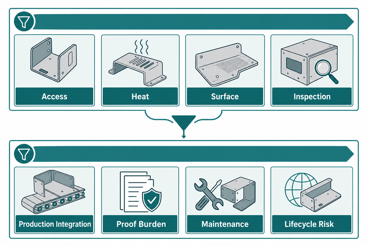
Use the two passes of the route table. The first pass is elimination. Any route that violates a non-negotiable access, heat, surface, removal, material, geometry, exposure, inspection, etc. requirement is eliminated. The second pass compares only feasible routes on production integration, proof burden, maintenance, changeover, consumables, and lifecycle risk.
Example: prepainted steel joined to aluminum
Suppose the drawing calls for a clean show surface. The joint is in a narrow return flange. There’s no need for service separation, and the assembly experiences cyclic peel and exposure to humidity. Based solely on material selection, there’s no preferred process. First check if there’s sufficient clearance to punch and die a flange. If not, conventional clinching and SPR leave the shortlist regardless of potential coupon load. If thermal marking or coating removal is prohibited, several welding routes may leave. Adhesive bonding remains only if the paint interface, preparation, bondline, cure, humidity ageing, peel fatigue, and inspection plan can be controlled. Even if it wasn’t the preferred option, a blind fastener or redesign would be considered.
Now change one constraint: allow a hidden die-side mark and provide two-sided access. Clinching is now a choice to test even if it isn’t the preferred option. It’s still necessary to perform a stack trial, sectioning or measurement of geometry, testing in relevant load modes, assessing corrosion, and developing a plan to control the process and compensate for drift. This is why constraint-based selection is better than developing a list of best methods.
Joint-trial checklist — copy these into your technical request:
| Parameter | Recommended range | Why it matters | How to verify |
|---|---|---|---|
| Individual sheet gauges | Project drawing values in mm, including tolerance | Controls deformation, heat flow, bearing, and tool choice | Material certificate plus measured samples |
| Flange and overlap | Project minimum and maximum in mm | Defines local tool and edge envelope | Released drawing and representative parts |
| Coating or surface condition | Named coating and allowed damage limit | Changes contact, forming, bonding, emissions, and corrosion | Specification, photos, and post-trial inspection |
| Tool access | Available approach and throat dimensions in mm | Prevents selecting an unreachable process | Section drawing, CAD envelope, and assembly sequence |
| Load case | Project load, cycles, rate, and environment | Aligns trial evidence with service | Approved test plan and failure criteria |
| Visible-surface limit | Signed standard with dimensional limit where relevant | Prevents strength-only approval of an unacceptable part | Golden sample, photos, and gauge method |
| Production target | Required good joints per min or per shift | Connects joint feasibility to the cell | Timed representative run with reject accounting |
| Release evidence | Project-defined limits and sample count | Makes acceptance auditable | Traceable report, raw results, sections, and process records |
8. Prove the Route from Sample to Production
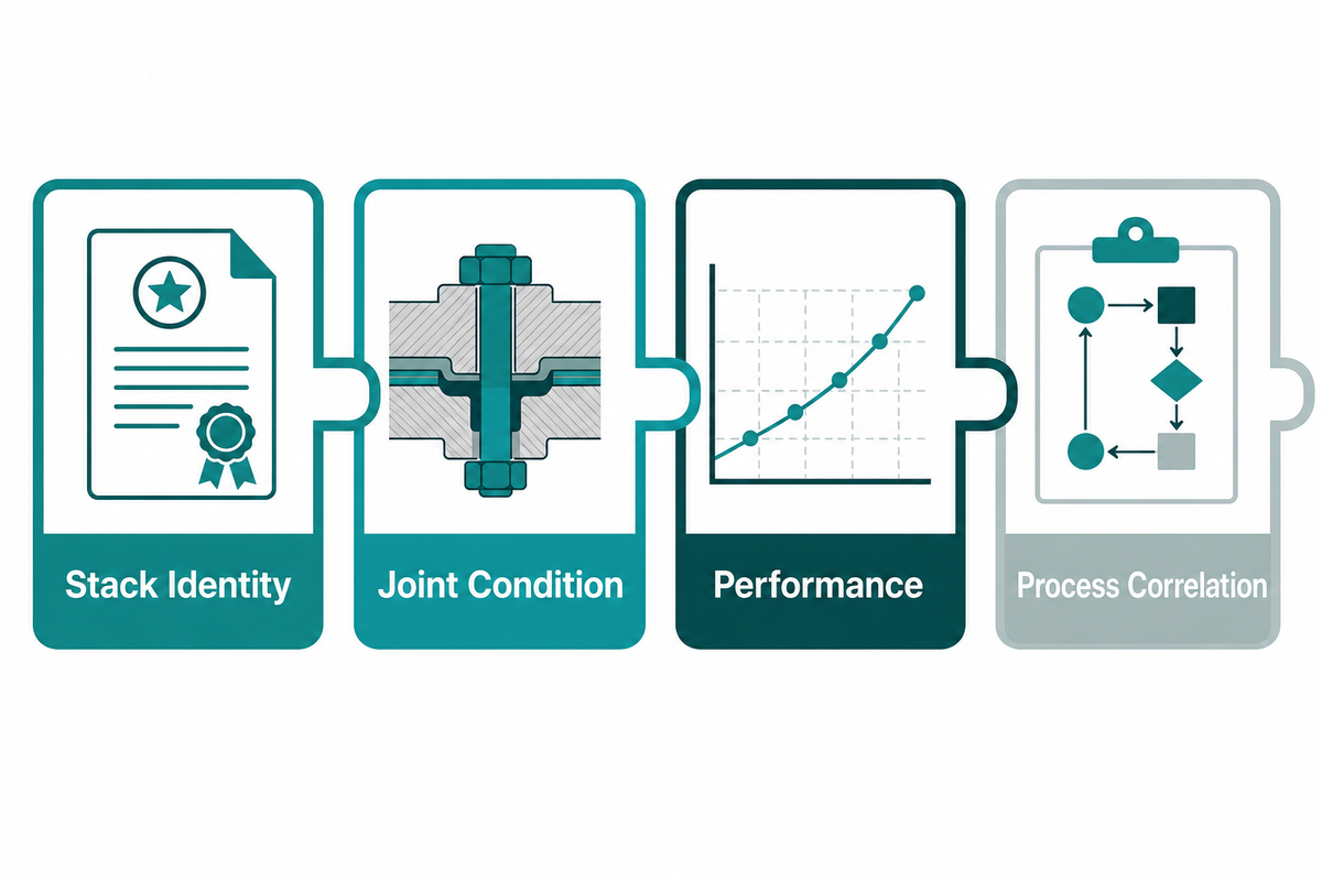
Once a feasible route survives the constraint screen, one attractive sample proves only that one sample was produced. To release a production sample, it is necessary to develop a chain that connects what was joined, what geometry was achieved, how it performed, and which process record can describe it.
| Layer | What to retain | What it does not prove alone |
|---|---|---|
| 1. Stack identity | Material certificates, gauges, coating, surface condition, stack order, drawing revision, sample ID | That the joint geometry or process was acceptable |
| 2. Joint condition | Both-face images, dimensions, sections where relevant, cracks, porosity, interlock, neck, nugget, head, tail, bondline | Static, fatigue, impact, corrosion, leak, or service performance |
| 3. Performance | Test method, fixture, load mode, rate, sample count, environment, raw results, failure mode, challenged conditions | Transfer to a differently stiff or differently loaded assembly |
| 4. Process correlation | Tool ID, settings, force/displacement/current/time record as applicable, material lot, alarms, acceptance window, reaction plan, change control | That every unmeasured service risk is closed |
ISO 12996 provides specimen geometry and a tensile-shear procedure for single mechanical joints on single-layer and multilayer sheets, including individual sheet thicknesses up to 4.5 mm within its stated scope. It contributes to the standardization of one mechanical evidence layer; however, it should not be considered a full fatigue, corrosion, sealing, cosmetics, or process control plan. ISO/TR 12998 adds fatigue-test guidance and reinforces the need to match load mode and stiffness.
Powered joining equipment requires, in addition, the assessment of each machine for associated risks. OSHA 29 CFR 1910.212 states “One or more methods of machine guarding shall be provided” and requires guarding at the point of operation where exposure would injure an operator. This rule constitutes a guarding limit, rather than a standard for selecting methods or a complete machine design.
Before release, define the reaction to a bad section, changed coating lot, replaced tool, electrode dress, adhesive excursion, altered cure, revised flange, software change, or moved fixture. A monitored curve is useful only if it’s correlated to accepted and rejected physical joints and has an agreed response outside the specified limits.
9. Mixed-Material Stacks Are Changing What “Best” Means

Trade reporting in 2025 highlights servo-electric clinching, in-process monitoring, difficult material combinations, and hybrid joining. In that article, supplier contributors describe examples from 0.3 mm to 7 mm per layer, total stacks of 14 mm or 22 mm in selected applications, and hybrid gains of 30% or more under stated conditions. Those are attributed supplier examples, not universal limits or guarantees, and each needs its own sample and test conditions.
The practical outlook is conservative: expect more hybrid concepts, monitoring, and dissimilar-material trials, but demand a tighter evidence chain. New technology does not remove the old questions about access, local stiffness, peel load, coating condition, corrosion, fatigue, inspection, repair, and process change. It increases the cost of pretending that one answer addresses everything.
10. When a Clinching Equipment Trial Is the Next Step
A clinching trial is worth consideration when the joint can tolerate a permanent cold-formed interlock, both sides are accessible, the flange and reaction path are reasonable, the material stack appears formable, and the project can define the appearance and test criteria. Don’t start with a predetermined press force or machine model. Start with the 8-Input Joint Brief and exemplar components.
Send the upper and lower material specifications, individual gauges and tolerances, stack order, coating and lubrication condition, joint area, access envelope, permissible marks, target production, and the planned mechanical and environmental tests. Ask the supplier to return sample and tooling identities, a process record, joint geometry or sections where appropriate, raw test data, failure modes, and any limitation that still requires customer validation.
When clinching passes the route screen, evaluate SIMITCH’s clinching machines and equipment options once the stack and target acceptance have been established. The equipment page controls configuration and quotation, while this guide retains the method-selection and proof framework.
SIMITCH reports that it was founded in 2006, has 20 years of R&D experience, supports more than 3,000 manufacturing clients, and has equipment in service across 41 countries. When comparing sheet metal joining techniques, treat these as company-reported credentials for support capacity—not as proof that a particular joint will pass validation.
Have a thin-sheet stack ready for review?
Share the two sheet specifications, gauges, coating, joint drawing, access envelope, production target, acceptance method, visible-surface limits, likely service environment, and service-life constraints. SIMITCH’s sheet-metal joining team can then discuss whether a clinching trial is technically relevant before equipment selection.
Frequently Asked Questions
What are the common methods for joining sheet metal?
Typical methods include resistance spot welding; MIG, TIG, and laser welding; brazing and soldering; clinching; riveting and self-piercing riveting; threaded or inserted fasteners; adhesive bonding; and combinations of the aforementioned techniques. The final choice would depend on the stack, coating, access, joint geometry, service load, visible-surface limit, repair requirement, and proof plan.
How can two pieces of thin sheet metal be joined without welding?
The choices are: clinching, conventional or self-piercing rivets, blind fasteners, screws or inserted hardware, adhesive bonding, folded or locked seams, and combinations of the aforementioned techniques. “Without welding” only removes fusion heat; it does not guarantee one-sided access, removability, no surface mark, or acceptable performance.
Is clinching suitable for coated sheet?
Clinching can suit coated sheet, but the result depends on the stack itself. A trial should check coating damage, cracks, button or interlock geometry, visible marks, corrosion exposure, and mechanical behavior using the actual coating, lubrication, material grade, thickness, stack order, punch, and die.
Does a stronger lap-shear coupon mean a better production joint?
No. The outcome is specific to the specimen, load mode, rate, environment, and local stiffness used in the test. Production selection also depends on peel or cyclic loading, corrosion, access, surface limits, inspection, process stability, repair, and the consequence of failure.
What should be included in a sheet metal joining trial?
Include traceable materials and coating ID, individual gauges, stack order, representative geometry, tool and process ID with both-face images, sections or dimensional checks as appropriate, and application-relevant mechanical and environmental tests. Keep raw data, specimen count, fixture, load mode, failure modes, process records, acceptance criteria, and change-control triggers. Include the hardest coating, tolerance, access condition, and service environment so the supplier does not produce a sample that production will never use during the intended production qualification process.
References & Sources
- TWI: methods for joining sheet metal
- Peer-reviewed review: Clinching for sheet materials
- Open study: steel, aluminum RSW with insert element and adhesive bonding
- Peer-reviewed study: interlayer-adhesive hybrid joining of aluminum, steel sheets
- ISO 12996:2013, tensile-shear testing of single mechanical joints
- ISO/TR 12998:2019, fatigue testing of mechanical joints
- ISO 17212:2012, surface preparation before adhesive bonding
- OSHA 29 CFR 1910.212, general machine guarding requirements
- OSHA: welding respiratory hazards, including zinc oxide
- NASA Kennedy Space Center: forms of corrosion
- AMPP: forms of corrosion
- Peer-reviewed review: adhesives, surface treatment, repair, and disassembly
- Open study: corrosion behavior of aluminum, galvanized-steel RSW joints
- Assembly Magazine: current clinching developments
![Hot-Melt Connection Molds & Equipment Guide [2026]](https://simitch.com/wp-content/uploads/2026/09/hot-melt-connection-molds-equipment-guide-featured-768x512.png)