Get in touch with Suzhou Simitch Machinery Co., Ltd Company

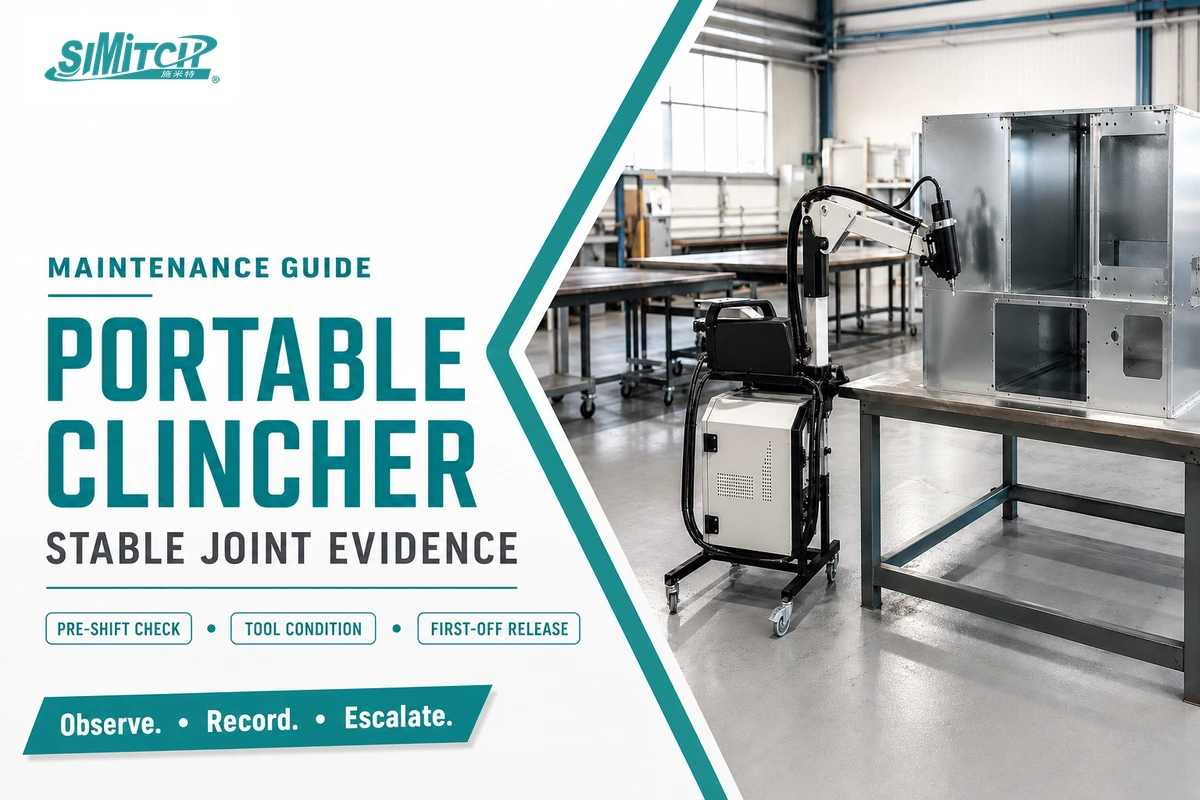
Updated August 2026 · Maintenance and quality guide
Portable clinching machine maintenance is most effective when treated as an evidence routine: preserve the approved tool and material setup, inspect the mobile installation, verify the first-off joint, and document what changed before any adjustment or servicing occurs. The current machine manual, approved control plan, employer safety procedure, and applicable jurisdiction govern the actual work.
Direct answer: Check identity, condition, support, utilities, permitted motion, first-off evidence, and change history. Stop when safety, tool condition, reset behavior, or approved joint evidence is compromised. Do not copy operating pressure, stroke, die depth, lubrication, or wear limits from another clincher.
Maintenance decisions in four lines
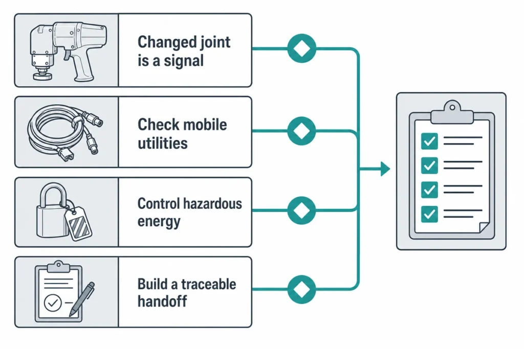
- Changed joint evidence is a signal to investigate, not proof that the punch or die is worn.
- Portable equipment adds hose, cable, suspension, handling, vibration, and operator-interface observations to ordinary tooling checks.
- Cleaning, jam clearing, guard removal, adjustment, and tool changes may require hazardous-energy control by an authorized role.
- Useful service handoffs are small, traceable evidence packets, not product-selection briefs or unfiltered folders of files.
Sheet metal clinching is a method for joining metal parts without additional fasteners. This maintenance guide starts after the clinching process is approved; comparisons with traditional joining methods remain in the existing clinching machines and equipment guide.
1. What Must Be Fixed Before Maintenance Starts?
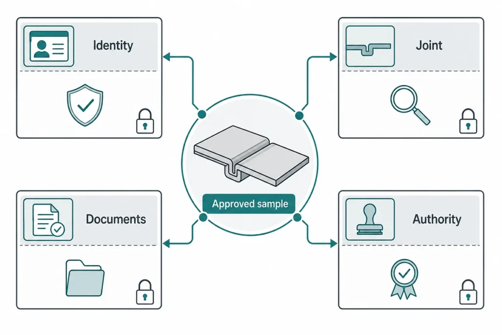
The exact machine, portable head, punch/die, approved sheet metal stack, joint or drawing revision, current manual, and intervention authority are prerequisites for assessing maintenance results safely. Without a baseline, two shifts may use the same term, “drift,” for different tools, materials, measurements, or criteria.
Observation and repair aren’t the same task. If unexpected startup or stored electrical, mechanical, hydraulic, or pneumatic energy could harm a worker, the employer’s energy-control procedure governs isolation, verification, and authorized roles. In the United States, OSHA 29 CFR 1910.147(d)(5)(i) requires potentially hazardous stored or residual energy to be made safe.
“All potentially hazardous stored or residual energy shall be relieved, disconnected, restrained, and otherwise rendered safe.”
Approved baseline card
- Identity
- Machine, portable head, punch, die, hose/booster or drive configuration
- Joint
- Drawing revision, material grades, thickness stack, coating, sheet order, approved sample
- Documents
- Current machine manual, setup sheet, control plan, last service record
- Authority
- Who may observe, isolate, remove a guard, clear a jam, change a tool, adjust a setting, and release production
The Site Trial Readiness Estimator can help organize information before an intervention, but it neither replaces a work order nor authorizes the work.
Key takeaway: maintenance evidence becomes comparable only after tool, joint, document, and authority identities are fixed.
2. What Is the 7-Signal Portable Clincher Pre-Shift Check?
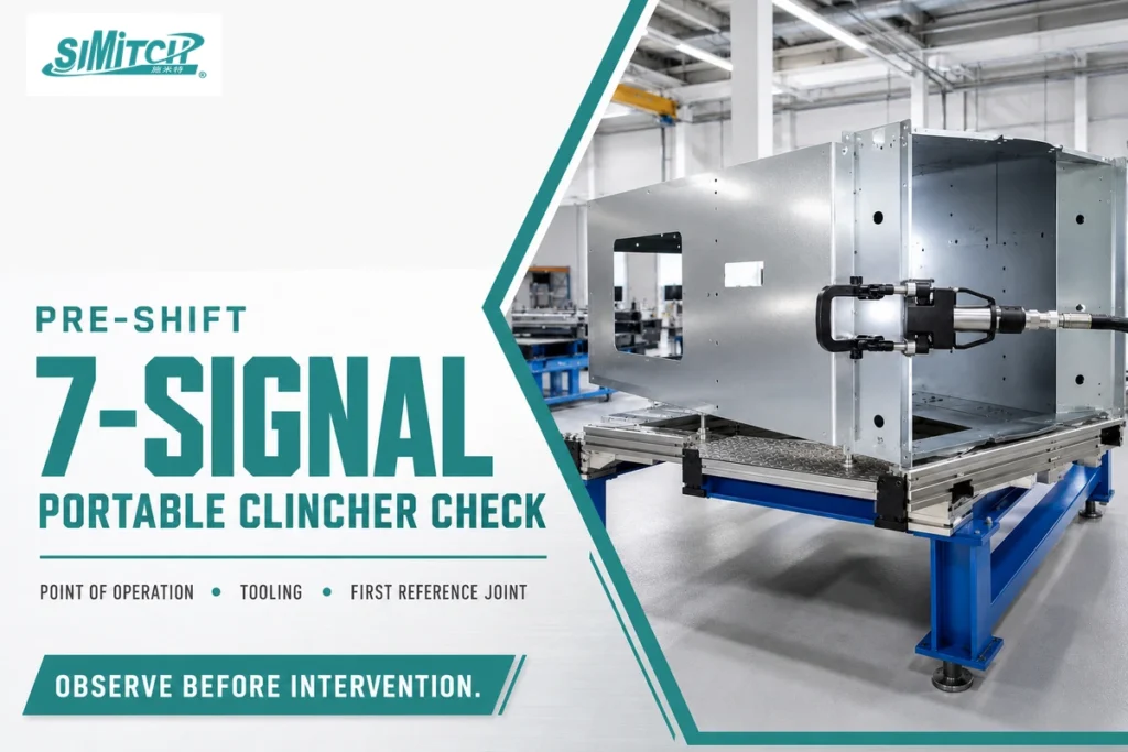
The 7-Signal Pre-Shift checklist covers observable conditions that portable clinching machines can encounter before the first production clinch. The signals include point-of-operation status, tool seating, visible damage or contamination, mobile supply condition, support and operator interface, permitted machine state, and a first reference-joint result. A failed signal routes the tool to the approved stop or review path; it doesn’t authorize a modification.
Portability changes what should be logged. The UK Health and Safety Executive’s power-tool guidance covers suitable use, training, lifetime maintenance, vibration performance, weight, grip force, handling, noise, and cold exhaust. Legal duties vary by jurisdiction, but joint output isn’t the only condition worth recording for a portable tool.
7-Signal Pre-Shift Check
| Signal | Observe | Record | Stop or review trigger | Evidence owner |
|---|---|---|---|---|
| 1. Point of operation | Guarding, access area, obstruction, visible damage | Normal / changed plus photo if changed | Compromised safeguard or unsafe access | Operator and safety owner |
| 2. Punch and die seating | Correct identity, seating, retention, obvious looseness | Tool IDs and seating status | Wrong, loose, damaged, or uncertain tooling | Operator; qualified maintenance for intervention |
| 3. Tool surfaces | Contamination, chipped edge, galling, eccentric mark, unusual surface change | Location and evidence class | Damage or condition outside the approved visual standard | Quality and maintenance |
| 4. Mobile supply path | Hose, cable, connector, supply lines in the machine, routing, pinch or abrasion | Location and condition | Leak indication, exposed conductor, kinked or crimped lines, damaged fitting | Operator and maintenance |
| 5. Support and interface | Suspension or balancer, attachment, grip, handling, unexpected vibration, noise, cold exhaust | Changed / unchanged and when noticed | Loss of support, unstable handling, abnormal vibration or noise | Operator, safety, maintenance |
| 6. Permitted status check | Indicator state and only the dry motion, full stroke, or reset check allowed by the current manual | Observed state without altering settings | Machine will not open up or reset as expected, or status is ambiguous | Operator; service owner for diagnosis |
| 7. First reference joint | Approved visual, dimensional, section, or load evidence required by the control plan | Result, method, gage, disposition | Missing evidence or result outside the approved limit | Quality release owner |
Use compressed air for cleaning only when the current manual and site procedure permit it. In the United States, 29 CFR 1910.242(b) requires pressure below 30 psi for cleaning and also requires effective chip guarding and personal protective equipment. That task-specific limit is not a clinching-machine operating-pressure setting.
Key takeaway: observe seven states, preserve the evidence, and route abnormal conditions; never turn a pre-shift check into an improvised repair.
3. How Should You Read Punch and Die Wear?
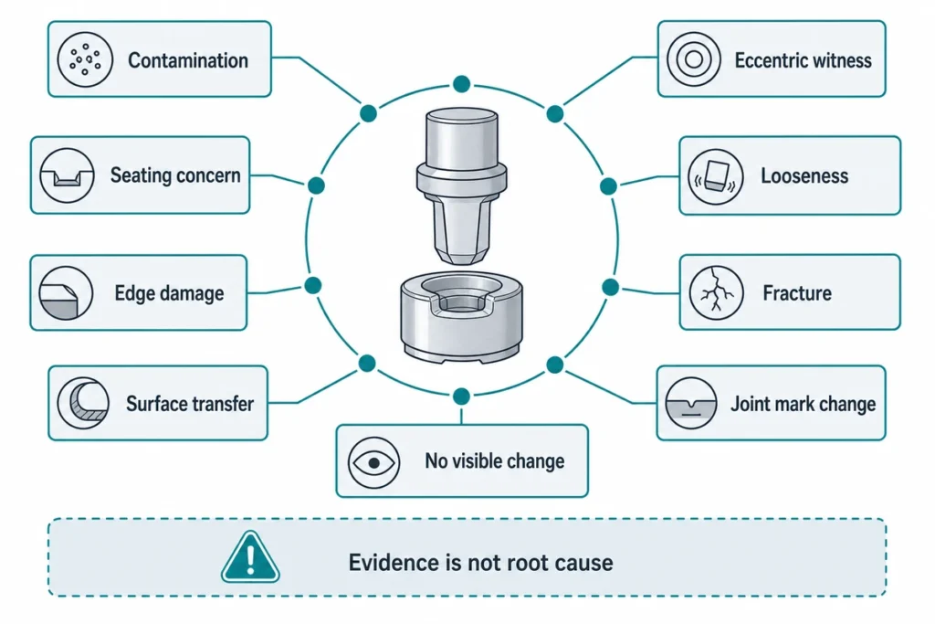
Describe tool condition in distinct evidence classes: contamination, seating, visible edge damage, looseness, eccentricity, transfer marks, fracture, or unexplained change. A tooling choice or setting is governed by the approved setup; a mark that appears to be caused by the die still isn’t a diagnosis. Different conditions require different routes: approved cleaning for one, or isolation and qualified inspection for another. Neither route supplies a universal wear limit.
The peer-reviewed review Clinching for Sheet Materials relates joint behavior to neck thickness, undercut, bottom thickness, punch-and-die geometry, equipment adjustment, and load direction. Those relationships explain why a tool mark deserves attention without turning that mark into proof of root cause.
Tool condition evidence matrix
| Condition type | What is visible | What it may mean | Permitted evidence action | What it cannot prove |
|---|---|---|---|---|
| Contamination | Coating, adhesive-like transfer, chips, embedded debris | Surface interference or material transfer | Photograph; follow approved cleaning method | Permanent wear |
| Seating concern | Gap, changed reference position, uncertain retention | Incorrect installation or looseness | Stop and route to qualified inspection | Correct alignment after reseating |
| Edge damage | Chip, crack, missing corner, rolled edge | Tool damage | Isolate and preserve the tool/joint evidence | Remaining service life |
| Surface transfer | Pickup, galling, polishing, scoring | Contact or material/coating interaction | Compare location, lot, stack, and last accepted sample | That the tool alone caused drift |
| Eccentric witness | Asymmetric mark or uneven contact | Possible alignment, support, or stack issue | Record orientation and escalate for setup review | Magnitude of misalignment |
| Looseness | Movement or retention change | Unsafe or unstable tooling condition | Stop; use authorized intervention path | That tightening is the correct repair |
| Fracture | Crack or broken element | Loss of tool integrity | Stop and quarantine affected output | When the fracture began |
| Joint mark change | Button, impression, or section differs from reference | Tool, material, setup, utility, support, or measurement change | Run the controlled-variable review | Root cause or joint strength |
| No visible change | Tool and surface appear normal | No obvious surface evidence | Keep required first-off and trend checks | That hidden geometry and load behavior are accepted |
Key takeaway: label what you observed before naming what failed. “Wear” is a conclusion that needs configuration and joint evidence.
4. What Can a Changed Clinch Joint Prove?
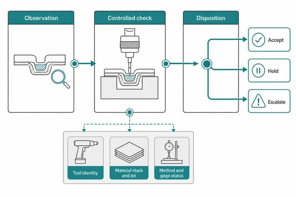
Evidence relevant to a possible clinch joint failure may include a button, section, dimension, or load result that differs from its approved reference. That change doesn’t prove tool wear, root cause, or joint capacity. Before assigning cause, compare the material lot and history, grade, thickness stack, coating, sheet order within the stack, tooling alignment, utility state, support, interventions, and the measurement process.
Tooling can remain unchanged while the joint result moves. In one 2022 analogue study, a 9% thickness-tolerance variation reduced modeled interlock to about 40% of nominal, while tool misalignment around 1.5 degrees was highly disruptive. These are study-specific findings, not portable-clincher tolerances.
A 2026 production-focused paper adds another boundary: production conditions don’t always reveal sheet-processing history unambiguously. When the evidence can’t separate tool, material history, setup, and measurement effects, retain the uncertainty instead of forcing a quick cause.
Observation → controlled check → disposition
- Observation: describe the changed button, impression, section, test result, orientation, and time.
- Controlled check: compare tool identity, material stack/lot, sheet order, setup, utility status, last intervention, method, and gage status.
- Disposition: accept only against the approved control plan; otherwise stop, hold affected output, and escalate.
Illustrative record, not a Simitch customer case: suppose a section value changes after a tool change. Preserve both tool IDs, material lot, sectioning method, gage ID, calibration status, result, disposition, and approver. No acceptance limit is implied by this example.
Key takeaway: joint appearance is evidence of change, not proof of wear. Treat unresolved variables as unresolved.
5. What Must Be Verified After Cleaning or a Tool Change?
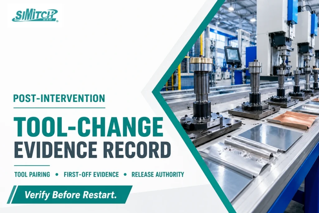
After an approved tool change or cleaning action, verify the tool pair, seating, material reference, machine state, measurement method, gage, required evidence, and named release owner before production starts. Keep these facts in the Tool-Change Evidence Record. Acceptance limits remain those in the approved drawing, control plan, test method, and current machine documentation.
NIST measurement-process guidance explains that recorded data can move through bias or variability. A number can look acceptable even after the person, machine, fixture, gage, check standard, or calibration status has changed. A valid first-off record therefore links the machine intervention to the measurement process.
Tool-Change Evidence Record
| Field | Record | Release question |
|---|---|---|
| Timestamp and shift | Date, time, shift, operator | Can the event be placed in the production history? |
| Machine and portable head | Unique identity and configuration revision | Was the correct equipment reviewed? |
| Punch and die | Both tool IDs and approved pairing | Do they match the controlled setup? |
| Intervention | What was cleaned, changed, reseated, or inspected; responsible role | Is the action authorized and traceable? |
| Material stack | Grades, thicknesses, coating, order, lot | Does it match the approved reference? |
| Reference joint | Drawing/sample/control-plan revision | Is the comparison target current? |
| Measurement process | Method, fixture, gage ID, calibration/check-standard status | Can measurement drift be separated from process drift? |
| First-off evidence | Visual, button, section, dimensional, or load result as required | Does every required result meet its approved limit? |
| Disposition | Accept, hold, reject, retest, service review | Is the next state explicit? |
| Approver | Name or controlled identity and role | Was restart approved by the assigned authority? |
Organize the material stack and supporting evidence with the Joint Review Readiness tool before an engineering review. The tool organizes inputs; it doesn’t rule that the joint is acceptable.
Key takeaway: production release needs controlled first-off evidence and an owner; a visual glance or undocumented trial cycle is not a release record.
6. How Do You Build a Portable Clincher Drift Ledger?

Organize the Portable Clincher Drift Ledger around identity, time, material, observation, intervention, measurement, and disposition. The ledger preserves sequence so a reviewer can see when events coincide and how combined changes may relate to the result. Keep field meanings stable across shifts, and treat gage bias or variability as possible contributors to apparent drift.
NIST’s measurement data-management work tracks configuration variables with their history. It doesn’t endorse this article’s exact ledger. The transferable idea is configuration traceability: a record that reconstructs the physical and measurement history behind each result.
Portable Clincher Drift Ledger: 11 load-bearing fields
| Field | What to enter | Why it matters |
|---|---|---|
| 1. Time | Timestamp and shift | Places change in sequence |
| 2. Equipment identity | Machine and portable-head ID | Separates configurations |
| 3. Tool identity | Punch/die IDs and pairing | Tracks tool history |
| 4. Joint control | Drawing or approved-joint revision | Fixes the comparison target |
| 5. Material | Grade, thickness stack, coating, sheet order, lot | Preserves input variation |
| 6. Pre-shift signal | Observed state or change | Captures evidence before intervention |
| 7. Permitted status | Utility/indicator status allowed by the manual | Records state without copied settings |
| 8. Intervention | Action and responsible role | Links change to authority |
| 9. Measurement and result | Method, gage/calibration status, value with unit, section or test result | Separates measurement from process drift |
| 10. Disposition | Accept, hold, reject, retest, escalation; release owner | Closes the decision |
| 11. Evidence link | Photo, retained sample, test file, or service record | Lets another role verify the entry |
These 11 fields are not mandated by ISO 10007:2017, which gives configuration management guidelines in general across the lifecycle of a product or service. Simitch has created the ledger to organize information about a portable clincher so that its history is reviewable without drawing unsupported conclusions from observed correlations.
Key takeaway: log enough to reproduce the state, then let the approved evidence and assigned roles decide what the trend means.
7. When Should You Stop, Inspect, or Escalate?
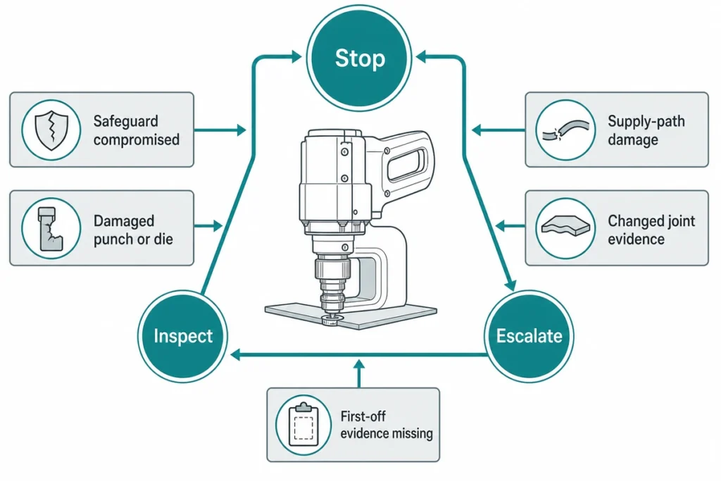
Stop when a safeguard, portable support, hose or cable, tool, reset state, or approved first-off result is compromised. Qualified inspection may proceed only under the current machine manual and the applicable hazardous-energy control procedure. Escalate when cause, configuration, measurement validity, or acceptance evidence remains uncertain; recording a symptom never authorizes a setting change.
Stop-Inspect-Escalate Loop
| Observable evidence | Immediate route | Required record | Escalation owner |
|---|---|---|---|
| Point-of-operation safeguard compromised | Stop; prevent use; follow site safety procedure | Condition, time, equipment ID, photo if permitted | Safety and authorized maintenance |
| Damaged punch or die | Stop; preserve tool and affected joint | Tool IDs, damage location, last accepted evidence | Quality, maintenance, supplier support |
| Loose or uncertain tool seating | Stop; do not improvise tightening | Tool identity, observed movement, last intervention | Qualified maintenance |
| Contamination without an approved cleaning route | Stop and obtain the applicable method | Material, location, photo, suspected source | Maintenance and safety owner |
| Hose, cable, connector, or supply-path damage | Stop; isolate as required | Location, damage class, utility state | Authorized maintenance |
| Suspension, balancer, grip, or handling change | Stop if support or control is unstable; assess exposure | Condition, unexpected vibration/noise, operator report | Safety and maintenance |
| Machine will not open or reset normally | Capture the state; follow the manual; do not copy switch, oil, pressure, or power adjustments from another machine | Indicators, obstruction/damage, utility indication, last action | Configuration-specific service |
| Changed joint evidence | Hold output; run controlled-variable comparison | Joint, stack, lot, tool, setup, method, gage status | Quality and process owner |
| Failed or missing first-off evidence | Do not release production | Required result, actual result, method, disposition | Named release authority |
Why Won’t a Portable Clinching Machine Reset?
A system reset failure does not identify one cause. Treat it as an unresolved machine-state signal, not a diagnosis. On pneumatic machines, an approved status check may confirm that the air supply is active and reaches all specified supply points; it still doesn’t establish operating pressure, flow, or serviceability. Document the exact machine state, visible damage or obstruction, permitted utility indication, and last operator interaction, then consult the current manual and applicable isolation procedure.
Don’t increase power, change a pressure regulator, add fluid, adjust depth, or run an arbitrary number of cycles because a generic publication suggests it. Those actions may be wrong for the installed configuration. A slower, traceable diagnosis is safer than creating a second quality or safety problem through unauthorized work.
Key takeaway: stop on compromised evidence, inspect within assigned authority, and escalate before settings or internal service become guesswork.
8. What Should You Send Simitch for Configuration Support?
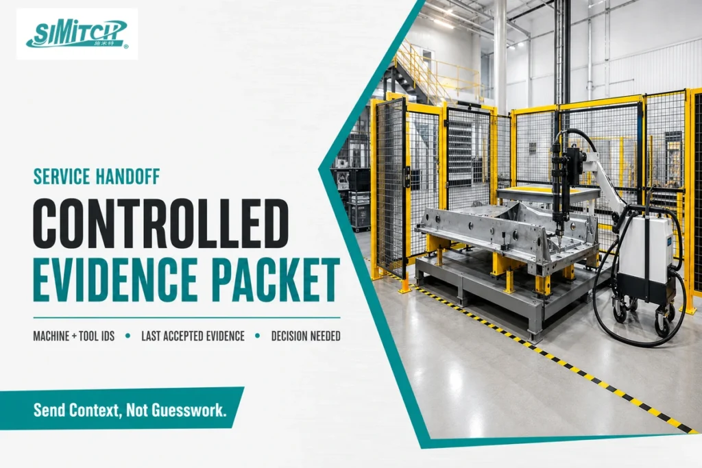
Send the minimum traceable evidence: machine and portable-unit identity, punch and die IDs, current joint or drawing revision, material stack and lot, last accepted condition, measurement equipment and status, representative results, prior actions, symptoms, and recent changes. Add large attachments only when requested so the engineering question stays visible.
Separate three things in the message: what is installed, what changed and when, and what decision or support is needed. This structure follows the provenance logic in NIST data management and the lifecycle configuration principle in ISO 10007:2017; neither source mandates this exact packet.
- Machine, portable head, booster/drive, punch, and die IDs
- Approved drawing or joint revision and last accepted reference
- Material grades, thickness stack, coating, sheet order, and lot
- Timestamped symptom and current stopped/held status
- Last intervention and responsible role
- Measurement or test method, gage ID, calibration status, result, and unit
- Focused photos, section images, retained-sample ID, or test record
For product-family context and configuration options, use the dedicated Portable & Handheld Clinching Machines solution page. Use that page to compare configurations or request a quote; this maintenance guide doesn’t compare configurations or quote prices.
Need a configuration-specific review?
Send the controlled evidence packet so Simitch can review the actual tool, joint, material, and intervention context. Include equipment and tool IDs, current drawing or joint revision, material stack and lot, last accepted evidence, observed state, last intervention, measurement method and result, and the decision you need.
Key takeaway: a concise, traceable packet helps engineering support answer the real configuration question without guessing.
Frequently Asked Questions
A portable clinching machine needs checks that protect both the clinching head and its mobile installation.
What maintenance does a portable clinching machine require?
Confirm the approved tool pair and inspect visible damage, mobile utilities, support, and handling. Compare the first joint with its approved reference, record the result, hold output when evidence is missing, and use the current manual for configuration-specific intervals, lubrication, settings, and internal service.
Use a general guide to organize evidence, but use the current machine manual to govern the work.
Should I use a general maintenance guide or the manual for my specific tool?
Use this guide for observations and first-off evidence; it does not authorize servicing. The current manual governs tasks involving stored energy, guarding, lubrication, pressure, stroke, controls, disassembly, parts, or reset procedures, together with the employer’s safety process. If documents conflict or the installed configuration is unclear, stop and send the equipment IDs, document revisions, observed state, last intervention, and held-output status to the assigned technical owner. Include the affected joint lot and the held-output disposition in that package.
After a punch or die change, verify the controlled setup and complete the required first-off evidence before release.
What should be verified after a clinching punch or die change?
Check tool IDs, approved pairing, seating, material stack, reference joint, and machine state. Record the method, gage ID, calibration status, result, and disposition. Release production only when the assigned authority confirms every control-plan requirement and identifies the retained record for traceability.
Stop a portable clinching tool when safety, physical condition, reset behavior, or approved joint evidence is compromised.
When should a portable clinching tool be stopped and sent for service?
Stop for a compromised safeguard, damaged tool or utility, unstable support, reset failure, or failed first-off evidence. Preserve the affected joint, tool identity, and last known machine state. Follow the applicable hazardous-energy control procedure and never alter undocumented machine settings.
Final Maintenance Rule
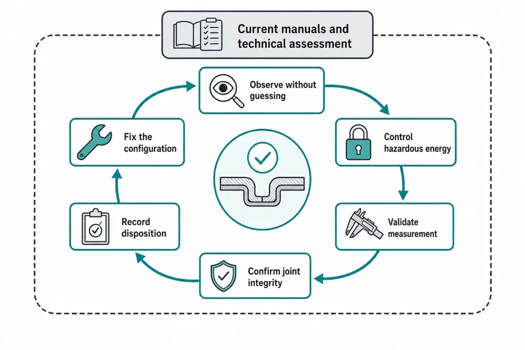
Regular maintenance should leave a straightforward path that other operators, quality personnel, field technicians, or suppliers can follow. Fix the configuration, make observations without guessing, control hazardous energy where appropriate, validate the measurement process, confirm the integrity of the joint against the approved criteria, and record the disposition.
Simitch provides intelligent joining technology and system-level solutions tailored for applications in automotive components, batteries, solar photovoltaic equipment, home appliances, and HVAC systems. For an overview of Simitch’s product range, please consult Simitch clinching equipment solutions. Service decisions for a specific machine remain dependent on the relevant manuals and a technical assessment of the installed configuration.
References & Sources
- OSHA 29 CFR 1910.147 — The Control of Hazardous Energy. U.S. servicing and stored-energy scope.
- OSHA 29 CFR 1910.242 — Hand and Portable Powered Tools. Compressed-air-cleaning rule; not operating pressure.
- UK HSE — Select Equipment for Reduced Vibration Exposure. Portable-tool suitability, maintenance, handling, and ergonomic factors.
- ISO 4414:2010 — Pneumatic Fluid Power. General pneumatic-system safety scope; not a model-specific service manual.
- ISO 10007:2017 — Guidelines for Configuration Management. General lifecycle guidance; no mandated 11-field ledger.
- Clinching for Sheet Materials. Peer-reviewed review of joint geometry, tooling, materials, and behavior.
- Multiscale Analogue Modelling of Thickness Tolerance and Tool Misalignment. Study-specific counterexamples to one-symptom/one-cause diagnosis.
- Influence of Plastic Machining on the Quality of a Clinching Joint in Aluminum. Limits on identifying sheet-processing history in production conditions.
- NIST/SEMATECH — Statistical Control of a Measurement Process. Measurement bias and variability across time.
- NIST NCAL — Data Management. Material, test, machine-configuration, and provenance records.
Scope note: This article provides an evidence and escalation framework. It does not replace the installed machine’s manual, approved control plan, employer safety program, qualified risk assessment, or applicable law. Technical review by Suzhou Simitch Machinery Co., Ltd. is required before WordPress publication.