Get in touch with Suzhou Simitch Machinery Co., Ltd Company


Torque specs define the tightening torque and conditions for a particular fastened joint. For repair work, use the approved component procedure. For a new assembly, engineers establish the required clamp load and characterize the actual bolts and mating parts, then qualify the tightening method. The bolt diameter alone won’t provide the correct torque.
A number on a controller isn’t helpful without context. A change in coating, washer, locking feature or part fit can alter what that number achieves. This method connects joint requirements to a usable specification, with a conditional calculation and separate budgets for tool calibration and joint testing.
Torque Specs: Meaning, Units and the Right Source
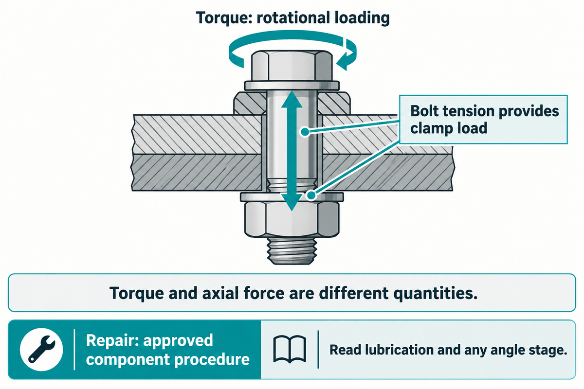
A torque specification describes the rotational loading used to tighten a fastener, usually in newton-meters or pound-force-feet. The specific torque applies to the installed nut or bolt under the stated conditions. The resulting tension in the bolt provides clamp load across the joint. Torque and axial force are different quantities and a torque wrench measures the former and joint testing will define the relationship to the latter.
Unit conversion is straightforward. Using the NIST Guide to the SI conversion table, 20 lbf·ft × 1.355818 = 27.11636 N·m, or about 27.1 N·m. Changing the units leaves the physical torque unchanged.
How do I find torque specs for my vehicle?
For the correct vehicle, year, engine and component, find the procedure in the manufacturer’s service manual, or in the approved service information. Read the entire installation procedure, including lubrication, replacement-fastener instructions and any angle stage. A wheel lug nut, brake caliper bolt and cylinder head bolt may require different procedures on the same vehicle.
For an automotive repair, identifying the operation and part is important. For example, replacing a tire is different from replacing an axle or rebuilding an internal combustion engine. Water pump bolts, transmission fasteners and manifold fasteners have different instructions. An engine’s output torque is a performance rating, not an assembly setting for its bolts and nuts.
Bolt Torque Charts: Match Grade, Thread and Surface Condition
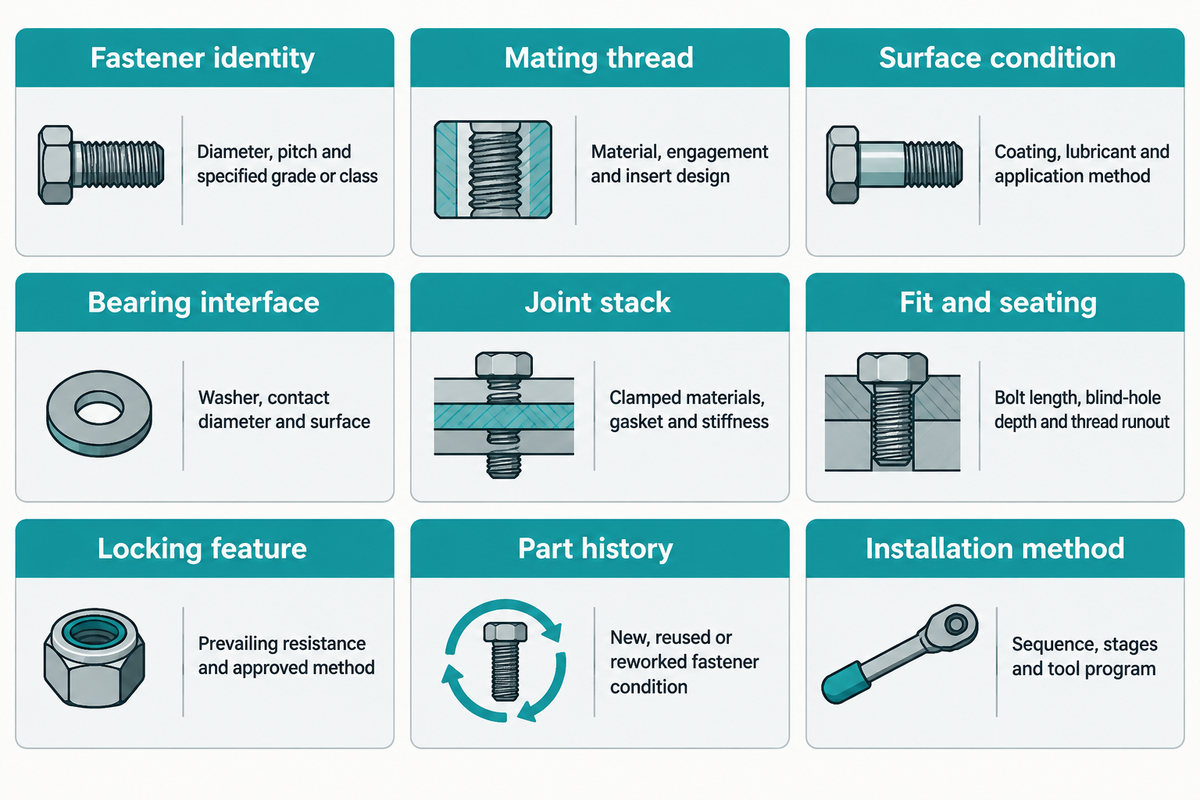
A bolt torque chart is valid only for the stated fastener and friction conditions and loading. SAE grades and metric property classes are different identification systems, and matching diameter doesn’t mean they’re equivalent. Before transferring a chart value, match joint conditions and ensure the bolt can seat without interference.
The chapter on torque in the Fastener Design Manual, reproduced by the Engineering Library from the NASA manual, shows the significance of footnotes. Its historical Table V assumes a thread friction of 0.12 and a bearing friction of 0.14. These inputs pertain to the chart, and not to every steel bolt that’s supplied today.
| Input class | What must match | Hidden failure or purchasing consequence |
|---|---|---|
| Fastener identity | Diameter, pitch and specified grade or class | A similar-looking replacement can have a different load capacity. |
| Mating thread | Material, engagement and insert design | The internal thread may strip before the bolt reaches its intended load. |
| Surface condition | Coating, lubricant and application method | A changed finish shifts the torque-to-clamp relationship. |
| Bearing interface | Washer, contact diameter and surface | A different washer changes friction and local pressure. |
| Joint stack | Clamped materials, gasket and stiffness | Compression changes seating and the angle needed after snug. |
| Fit and seating | Bolt length, blind-hole depth and thread runout | A bottomed bolt can reach torque without clamping the stack. |
| Locking feature | Prevailing resistance and approved method | The total tool reading can include torque unrelated to preload. |
| Part history | New, reused or reworked fastener condition | A worn coating or lock feature changes the process. |
| Installation method | Sequence, stages and tool program | A correct final value can accompany an incorrect assembly sequence. |
The fit checks described in NASA/JSC PRC-9007C, sections 6.2.1 and 6.2.5, apply here. For the most part, this matrix can serve as a review of the setup. Address incorrect bolt length and/or washer selection first, rather than spend more on a higher accuracy tightening tool.
Bolt Preload: Calculate Torque with the K-D-F Method
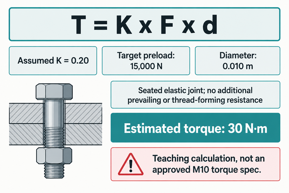
For an assumed, seated elastic joint with no additional prevailing or thread-forming resistance, K=0.20, diameter = 10 mm, and targeted preload = 15 kN give an estimated torque of 30 N·m. The simplified model is T = K × F × d. These teaching inputs describe a calculation, not an approved M10 bolt torque spec.
Think of the bolt as a spring stretched while the joint is compressed. The tensile force holds the parts together, and the applied torque must overcome friction. The nut factor K includes geometry and friction effects and is dimensionless. It’s different from the coefficient of friction between two particular surfaces.
Use metres for d and newtons for F when calculating T in N·m: 0.20 × 15,000 N × 0.010 m = 30 N·m. The NASA manual’s alternative torque formula also warns against blindly choosing a commonly assumed K. The design engineer must establish the target preload from the joint’s load, strength and retention requirements.
| Assumed K | Assumed target preload | Calculated torque |
|---|---|---|
| 0.15 | 10 kN | 15 N·m |
| 0.15 | 15 kN | 22.5 N·m |
| 0.15 | 20 kN | 30 N·m |
| 0.20 | 10 kN | 20 N·m |
| 0.20 | 15 kN | 30 N·m |
| 0.20 | 20 kN | 40 N·m |
| 0.25 | 10 kN | 25 N·m |
| 0.25 | 15 kN | 37.5 N·m |
| 0.25 | 20 kN | 50 N·m |
Compare torque values at a fixed preload: the estimate changes with K. This is why a purchasing decision about coating or lubricant belongs in the joint specification. At a fixed K, requesting more clamp load increases the torque estimate, but the equation doesn’t check bolt proof load, thread stripping, or whether a soft component will crush.
There are some minor differences with regard to the procedure for self-locking hardware. NASA/JSC’s procedure differentiates between running torque and effective preload torque. It adds measured running torque only when the engineering drawing specifies a value above running torque. Follow the approved convention; adding resistance to a value defined as total installation torque would count that resistance twice.
Dry vs Lubricated Bolts: Why Friction Changes the Result
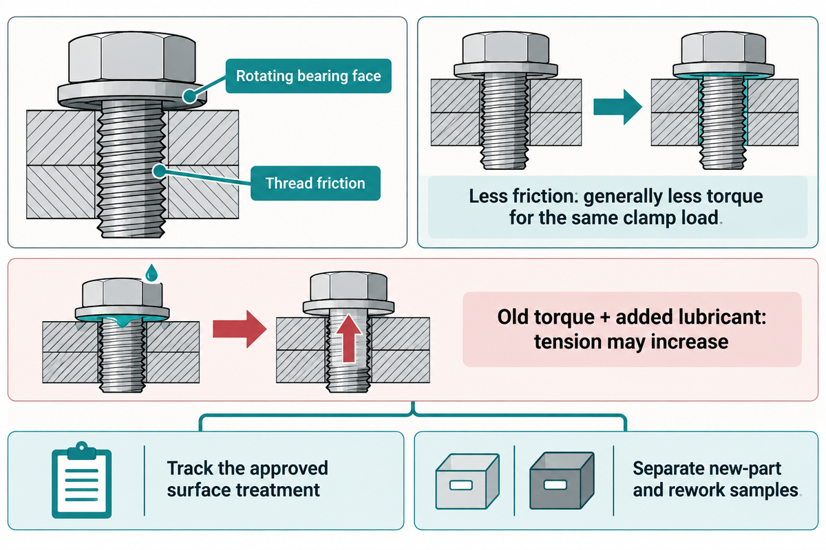
Less friction generally requires less torque to produce the same clamp load. Maintaining the old torque and adding lubricant may increase the tension and make the joint prone to over-tightening. Friction at the thread and the rotating bearing face resists motion as the bolt or nut turns. A specification developed for one finish should specify that condition precisely enough for production and purchasing to reproduce it.
ASSEMBLY’s How to Determine a Torque Specification discusses lubrication and coating as application variables. A blanket percentage discount for oil or grease hides differences between products and joints. Rust, debris, a replacement washer and a cured locking compound introduce other changes; “dry” alone is an incomplete description of a used assembly.
Reuse deserves its own trial condition. In Zimandy’s University of South Florida study of prevailing-torque locknuts, the hardware that was tested required changing tightening torque to achieve a given preload when it was reused. This supports separating new-part and rework samples rather than assigning the study’s reuse life to unrelated fasteners.
For a plant manager, the practical consequence is traceability: a supplier’s coating change could affect the tightening window even when the bolt dimensions on the drawing stay the same. Identify reworked parts and track the approved surface treatment. The quality team can investigate a shifted process without mixing first-installation and reuse results.
Torque-Tension Testing Before Production
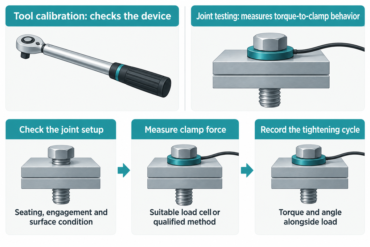
Torque-tension testing measures how actual joint hardware turns tightening input into clamp load. Tool calibration checks the measuring or setting device. Both matter, but they answer different questions.
Qualify the production-like stack, surfaces and methods of installation, then use the results to set acceptable torque and process limits.
ISO 16047:2005 describes torque/clamp-force testing, basically for specified steel metric fasteners from M3 to M39. Its public scope excludes thread-forming screws and fasteners with additional self-locking features. ISO 6789-2:2017 instead addresses calibration and measurement uncertainty for hand torque tools.
Plan the trial around real production parts depicting the joint design. For options on how to measure axial force during assembly see our document Measuring Axial Force During Assembly.
- Check the joint setup — Confirm seating, thread engagement and the specified surface condition.
- Measure clamp force — Use a suitable load cell, instrumented bolt or another qualified method.
- Record the tightening cycle — Capture torque and angle alongside load to compare the tool result with what the joint achieved.
A named industrial example shows the separate equipment role. Kistler’s ZF fastener-test-bench case reports capacities of 1,000 N·m total torque, 300 kN preload and 500 N·m thread torque for the bench commissioned in February 2018. These are the case equipment’s maximum capacities, not a suggested production window or a SIMITCH machine rating.
It’s important that retention testing distinguish motion from settling. According to Jon Ness in Simple Test Determines Cause of Loose Fasteners, relaxation can reduce clamp load without relative thread rotation. Thus a witness mark and recorded peak torque only partially answer the question on product quality. With the joint engineer, define the required service-loading and retention checks.
Torque-Only vs Torque-Angle Tightening
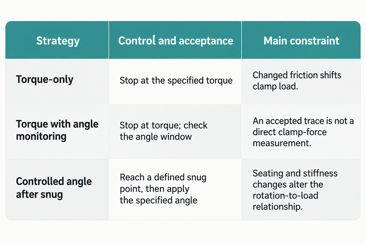
Torque control can suit a qualified torque to load relationship. Angle control, on the other hand, is dependent on joint stiffness and applies a defined angle after reaching the snug point. Adding angle monitoring to torque control provides another acceptance signal while leaving the torque stop condition in place. Which of the two methods would be appropriate depends on the behavior of the joint, measured using the methods described herein, rather than assuming that an angle-equipped tool would yield a better result.
| Strategy | Control and acceptance | Useful condition | Main constraint |
|---|---|---|---|
| Torque-only | Stop at the specified torque | Qualified, repeatable friction conditions | Changed friction shifts clamp load. |
| Torque with angle monitoring | Stop at torque; check the angle window | Extra detection of abnormal tightening traces | An accepted trace is not a direct clamp-force measurement. |
| Controlled angle after snug | Reach a defined snug point, then apply the specified angle | Consistent joint stiffness with variable friction | Seating and stiffness changes alter the rotation-to-load relationship. |
Torque control vs. angle control is assessed by David Archer in Torque Control vs Angle Control based on joint stiffness and friction. The clamped parts compress as the bolt stretches, so rotation is not consumed solely by bolt elongation. If the compressible gasket is part of the joint, its behavior would be quite different from that of a stiff and well seated steel joint.
“Joints with neither consistent stiffness nor friction require a return to the drawing board.”
Angle tightening also has an elastic form. Fukuoka’s study of the elastic angle control method examines stiffness and the inclination of bearing-surfaces. An angle stage by itself doesn’t indicate the bolt should yield.
Why do torque specs have a range?
Torque specs delineate a range that accounts for tool uncertainty and process variation while still supporting the required clamping function and remaining within approved joint and fastener limits. The lower limit must provide the required clamping function, and the upper limit must remain within approved joint and fastener limits. Tool uncertainty and process variation must fit within that plan. That range doesn’t allow the target to be set to a different location for each operator.
Specify the nominal setting, acceptable limits and the response to an out-of-window outcome in the work instruction. If the assembly is made up of multiple fasteners, tighten them in the prescribed sequence and stages. A breakaway reading reflects a changed friction condition, so don’t substitute an installation record with that reading unless an approved audit method mandates it.
Torque Wrench Calibration and Test-Service Costs
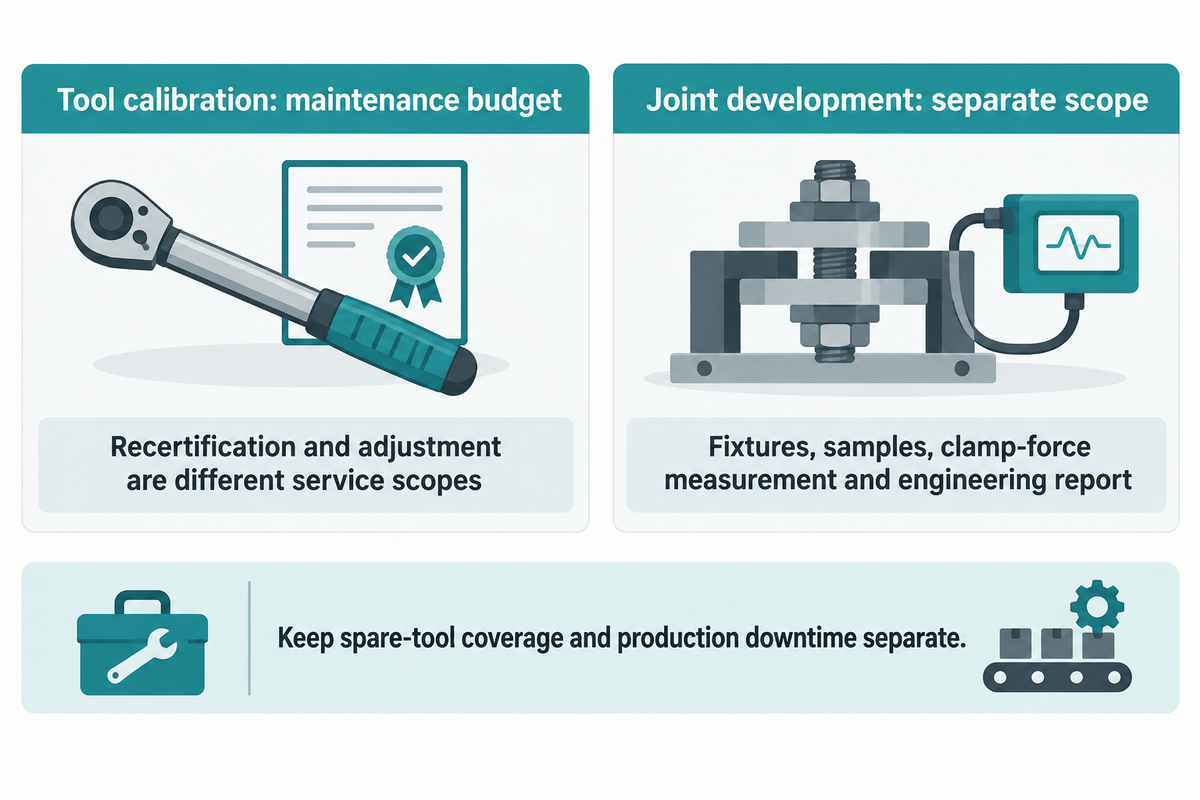
Published tool-calibration prices inform a small maintenance budget; application torque-tension development needs a separate scope. The published recertification-only charge for eligible US Tekton tools starts at $50; the service charge, including adjustment, starts at $75.
| Provider and scope | Published charge | Budget condition |
|---|---|---|
| Tekton: first eligible tool, recertification only | US$50 | US service; eligible Tekton models. |
| Tekton: first eligible tool, with adjustment | US$75 | Adjustment service differs from repair. |
| Tekton: additional tool in the same shipment | US$35 only / US$60 with adjustment | Batch rate; apply the correct service option. |
| Tohnichi: mechanical click tool below 280 N·m | US$50 per tool | Published schedule dated February 3, 2025. |
| Tohnichi: mechanical click tool, 280–700 N·m | US$70 per tool | Specific tool class and range; other classes differ. |
Sources: Tekton Torque Wrench Recertification Service and Tohnichi Repair and Calibration Fees. The dated schedule for Tohnichi may not reflect a recent quotation; shipping, repair and adjustment eligibility and turnaround should be part of the service order.
For a finance example, assume three eligible Tekton tools sent together: $50 + $35 + $35 = $120 for recertification only, or $75 + $60 + $60 = $195 with adjustment. The $75 difference is a service-scope difference, not a predicted saving. Keep spare-tool coverage and production downtime separate from the invoice.
Developing a motor-mount joint requires different inputs, e.g., fixtures, sample parts, clamp-force measurement, test conditions and an engineering report. Purchasing should request that scope be evaluated separately.
Torque-Controlled Tools and Test Equipment: Who Supplies What
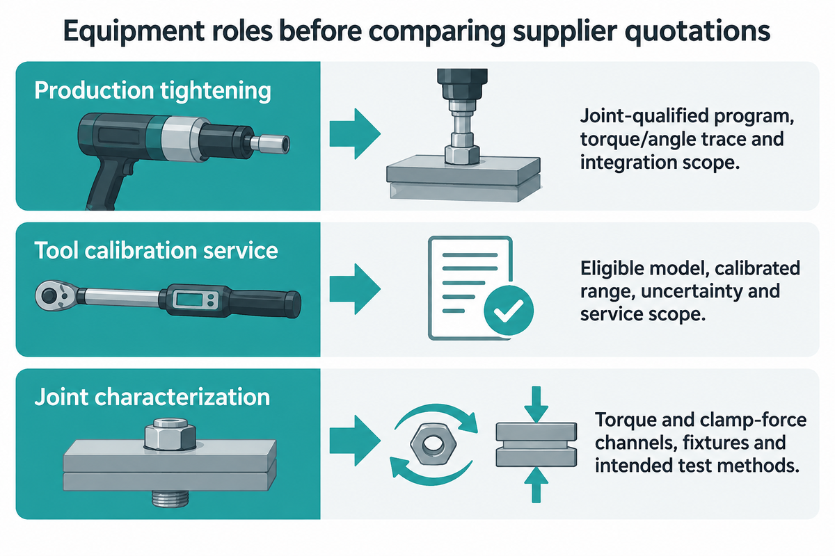
Evaluate production tools, calibration equipment and joint test equipment by their functionality. Suppliers may cover several categories; however, the required measurement and deliverable still differ. A tool used to fasten parts on a line doesn’t always come with the fixtures and force channels used to characterize a joint.
| Role | Public supplier example | What the buyer should request |
|---|---|---|
| Production tightening | Atlas Copco controlled-tightening systems | Joint-qualified program, torque/angle trace and integration scope. |
| Tool calibration service | Tohnichi hand-tool service | Eligible model, calibrated range, uncertainty and service scope. |
| Joint characterization | Kistler fastener-test bench | Torque and clamp-force channels, fixtures and intended test methods. |
ISO 5393:2017 concerns laboratory performance testing of generally continuous-torque powered assembly tools; impact, impulse and ratchet tools are excluded. For calibration equipment, PTB guideline DKD-R 10-8 treats the transducer through the display as a complete device. Ask which system the quotation actually covers.
To better integrate the line, compare assembly automation supplier roles with the tightening-tool offer.
Torque Control in an Automated Assembly Line
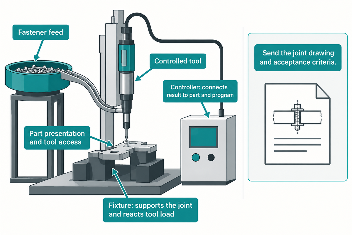
Automated fastening machinery integrates the part, fixture, fastener feed, and controlled tool. Accurate torque covers one of those functions. The fixture supports the joint and reacts the tool load. The controller connects the result to the part and program. Part presentation and tool access can determine station design before torque capacity does.
SIMITCH has built spindle, downholder, feeding and control integrated flow-drill fastening systems. This technology forms its mating thread as it joins the stack and hence requires process development for speed, axial load, depth and torque window.
Our workpiece testing and assembly capability allows us to discuss actual parts and joining requirements. A useful starting package contains a drawing, material stack, fastener and surface specification, together with the intended cycle and quality checks. That allows the integration discussion to address the job at the station instead of borrowing a torque rating from an unrelated machine.
A small-parts assembly automation project may also be restricted by feed orientation or tool clearance. These should be included with the fastening requirement. Linear servo press systems control a different joining action and their force-displacement curves shouldn’t be confused with the rotary torque-angle curves.
To look over other joining methods before specifying the station, use the sheet metal fastening methods guide .
Key takeaway
For a SIMITCH application discussion, send the joint drawing and the intended acceptance criteria so that tooling and sample-test scope can be defined together.
Fastening Outlook: Process Curves and Traceable Joint Data
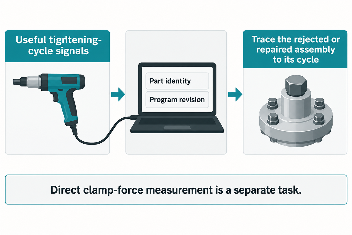
Process curves allow engineers to identify how a tightening cycle happened instead of just noting its final peak value. The key question is whether the station provides storage for useful signals with the part identity and program revision. More data is useful when an assembly that’s rejected or repaired can be tracked to its actual cycle.
Atlas Copco’s 2024 explanation discusses various seating-related control approaches and uses the term “clamp torque” to describe tightening. Direct measurement of clamping force is a separate measurement task; for the proposed station, request the available trace fields, retention method and reject-handling sequence as part of the integration scope.
Frequently Asked Questions
What is the torque spec for grade 5 bolts?
Grade 5 alone doesn’t determine a torque value; the setting also requires the bolt diameter, pitch, surface condition and mating assembly.
The grade identifies a strength category, while diameter, pitch, surface condition and the mating assembly determine which chart or procedure applies. For service work, retain the component manufacturer’s procedure; for a new joint, develop the setting from the approved preload and representative tests.
How do you measure the torque?
Measure applied torque with a suitable torque transducer or calibrated torque tool; measure axial clamp force separately.
A click wrench indicates a setting event, while a suitable instrumented system can record the torque during tightening. Joint testing may add a load cell or another qualified tension measurement. Distinguish those installation measurements from the torque needed to loosen an assembled fastener, because friction and joint condition can change after assembly.
Are torque to yield head bolts reusable?
Replace torque-to-yield head bolts when the identified engine procedure requires replacement.
Intentional yielding changes the fastener’s condition, and an angle stage alone doesn’t identify every bolt as torque-to-yield. Follow the reuse or replacement rule for that engine and bolt, including any specified inspection. A bolt that looks intact hasn’t thereby met the procedure’s dimensional, material or reuse requirements.
How tight is 20 ft lbs of torque?
Twenty lbf·ft is approximately 27.1 N·m.
That conversion describes rotational loading. The force applied at the handle also depends on its effective lever arm, and the suitability of this torque for a joint depends on the approved specification.
Do extensions affect torque specs?
An attachment that changes the effective lever arm can change the relationship between wrench setting and delivered torque.
Use the tool manufacturer’s method for the particular attachment geometry and direction of loading. An offset crowfoot and an ordinary socket extension are different arrangements, so a correction intended for one shouldn’t be copied to the other. Keep the joint’s required torque distinct from any corrected tool setting, and include the actual attachment in the setup instruction used by operators.
What is a good torque number?
There’s no single good torque number across applications: engine output torque and fastener tightening torque serve different purposes, and the approved value is specific to the job.
Engine output torque and fastener tightening torque describe different purposes. For an assembly, start with the required joint performance and its specified installation method.
What happens if you don’t torque to spec?
Insufficient clamp load can allow movement or separation, while excessive tightening can damage the bolt, thread or clamped component.
A soft gasket can be over-compressed, and a weak internal thread can strip before the external bolt fails. Some damage is visible immediately; other loss of function appears under service loading. Keep the specified sequence and surface condition as well as the final value. For an out-of-window production result, use the approved reject or repair route instead of simply tightening again.
References & Sources
- NIST Guide to the SI, Appendix B.9 National Institute of Standards and Technology
- Process Specification for Installation of Threaded and Collared Fasteners, PRC-9007C NASA Johnson Space Center, September 2020
- How to Determine a Torque Specification John Sprovieri, ASSEMBLY, 2017
- Prevailing Torque Locking Feature Wear-out Adam Joseph Charles Zimandy, University of South Florida, 2012
- ISO 16047:2005, Fasteners: Torque/clamp force testing International Organization for Standardization, public scope
- ISO 6789-2:2017, Hand torque tools: Calibration and measurement uncertainty International Organization for Standardization, public scope
- Simple Test Determines Cause of Loose Fasteners Jon D. Ness, ASSEMBLY, 2020
- Fastening Threads: Torque Control vs. Angle Control David Archer, ASSEMBLY, 2009
- Evaluation of the Tightening Process of Elastic Angle Control Method and Proposal of a Practical Tightening Operation Toshimichi Fukuoka, Japan Society of Mechanical Engineers, 2006; public abstract
- ISO 5393:2017, Rotary tools for threaded fasteners: Performance test method International Organization for Standardization, public scope
- Static calibration of calibration devices for torque wrenches, DKD-R 10-8 Physikalisch-Technische Bundesanstalt, edition 02/2020; public abstract