Get in touch with Suzhou Simitch Machinery Co., Ltd Company

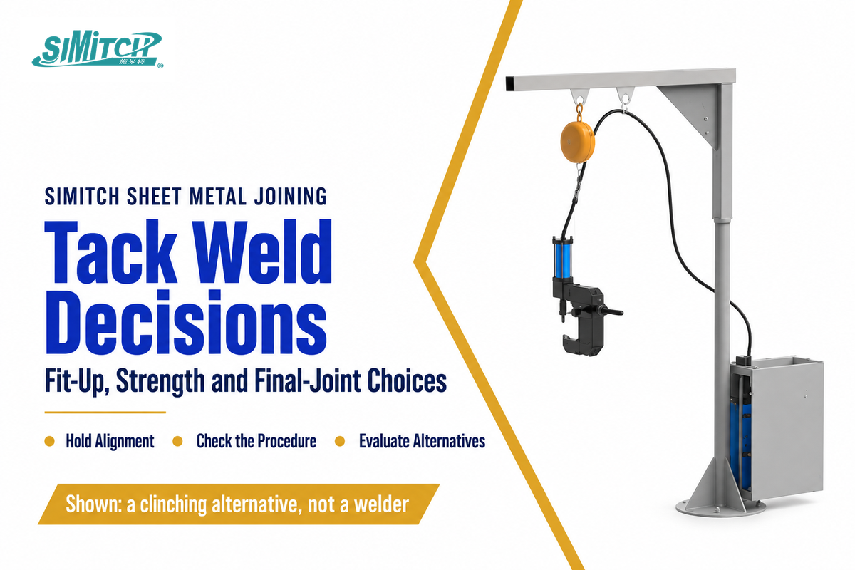
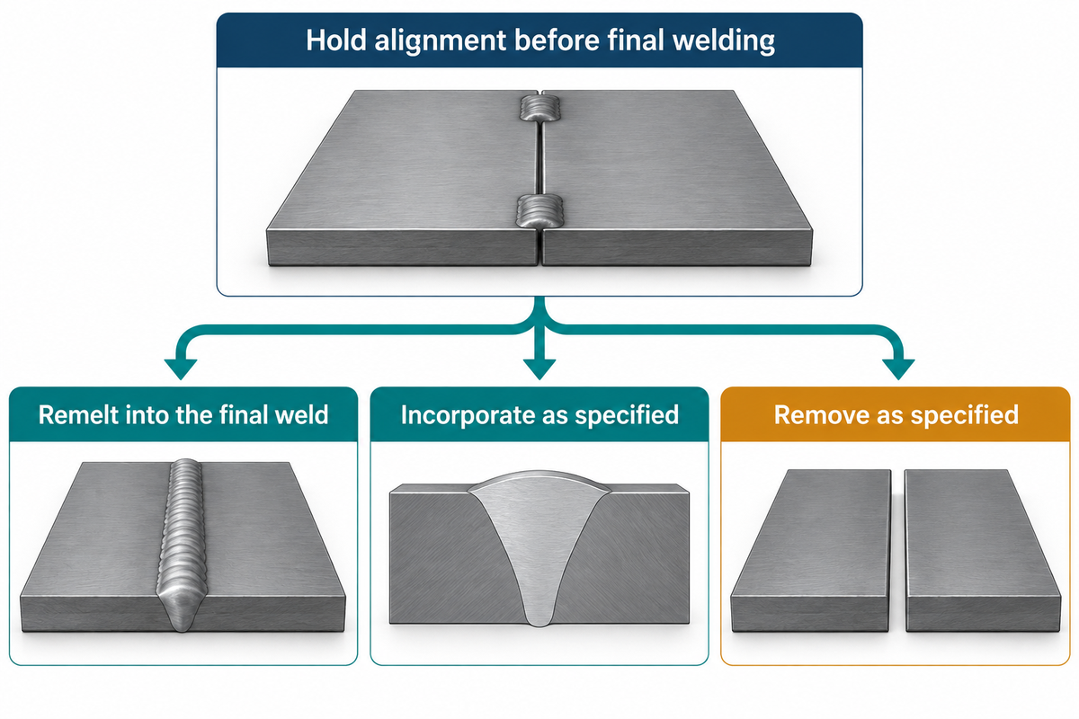
A tack weld connects parts in position before final welding. It keeps a joint aligned while the assembly is checked and completed. Some tacks are removed; others become part of the finished weld. The main decision is what each tack does during assembly and what happens to it afterward.
Updated October 2026
A tack weld is a positioning weld made before final welding. Its length, spacing and required strength follow the joint, handling loads and welding procedure. A small tack can still affect the finished joint.
Quick Specs
| Primary function | Hold alignment and fit-up before final welding |
| Possible processes | MIG, TIG or stick, where suitable for the joint |
| Drawing dimensions | Tack length, weld size, pitch and root opening are separate inputs |
| Final treatment | Remelt, incorporate or remove according to the procedure |
| Capacity | Evaluate the actual load and joint; no universal strength percentage |
- A tack left in the joint can become part of the final weld.
- Grinding the surface flush doesn’t prove that underlying damage is gone.
- Root opening and distance between tacks are different dimensions.
- Clinching and riveting are alternatives for suitable final joints, with their own geometry and access requirements.
What is a tack weld?
A tack weld can also hold two pieces of metal in their intended position, prior to the completion of the main weld. This is more a matter of purpose than a separate welding process. MIG welding or TIG welding may make both the tacks and the final weld when suitable for the joint, while the welding procedure determines how the two operations work in conjunction.
Tack welding is used when two or more pieces may shift during assembly, handling or heating. Clamps determine the starting position and the tacks help maintain it. A short weld along a joint may look like a small spot, but appearance doesn’t make it a resistance spot weld. The heat source and means of joining are different.
Duane K. Miller, Sc.D., P.E., makes the definition precise in the James F. Lincoln Arc Welding Foundation’s guide to tack and temporary welds: “The A3.0 definition does not define the length or size of a tack weld.” That distinction matters when a drawing calls for positioning over a longer joint.
Tack welding is a temporary positioning operation performed on many assemblies, but the deposited metal isn’t always temporary. Generally speaking, the planned treatment of deposited metal is decided before the joint is made. For additional information on finished joints and the methods used to effect them, refer to the metal joining methods guide.
Tack weld strength and disadvantages
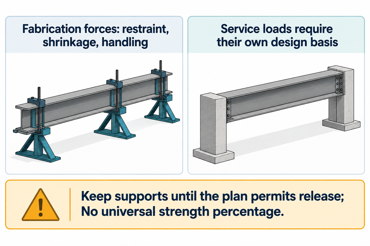
A proper tack is required to withstand the fabrication forces imposed on it due to restraint, shrinkage or handling. Service loads on a finished assembly differ from the fabrication loads imposed on its tacks. A joint that stays aligned on a bench has not thereby been demonstrated safe to lift, rotate or place in service.
Are tack welds strong?
If the alignment geometry, soundness and arrangement of the tack welds suit the applied load, they can provide substantial restraint. There’s no standard percentage of final-weld strength. Depending on the geometry, length, material and the direction of the load, strength can vary significantly. Keep specified supports in place until the handling plan permits release; visual attachment alone isn’t a capacity check.
Reasons for failure during handling that can lead to parts falling are discussed in The Fabricator’s technical discussion of tack welding. It also describes how small tack welds can cool rapidly, which makes material and procedure selection important even when little metal is deposited.
Advantages
- Preserves fit-up between assembly operations.
- Allows alignment checks before the joint is completed.
- Can work with the selected final welding process.
Limitations
- Adds local heat and possible movement.
- Creates quality requirements at each start and stop.
- May require removal or preparation before completion.
Easily overlooked when discussing the disadvantages of tack welding is that an incorrect tack can lock a poor fit-up in place. More weld metal deposited can make correction of a poor fit more difficult rather than easier.
How to tack weld: preparation and sequence
Prepare the surfaces, establish the specified fit-up, place tacks in the planned sequence, and recheck alignment prior to completing the joint. This overview organizes the work; the applicable welding procedure supplies the material-specific settings, consumables, preheat and acceptance requirements. Perform a representative trial when a new joint or setup is made. Sequence changes where shrinkage acts. Working progressively from one end can close a joint opening as the assembly moves.
- Confirm the joint. Identify the material, coating, drawing dimensions and final weld requirement.
- Prepare safely. Clean the metal surfaces using a welding-compatible method and establish the required exposure controls.
- Locate and clamp. Set the workpieces against the intended datums and check the opening.
- Apply the planned sequence. Use tack placement that controls movement without obstructing subsequent welding.
- Inspect and measure. Check soundness and fit-up before adding more restraint.
- Prepare for completion. Treat each tack as specified before making the full weld.
Balance may help, but a pattern copied from another part isn’t a qualified welding technique. TWI’s distortion guidance relates the result to joint design, preparation, and procedure, and the restraints in place.
3-Stage Fit-Up Check
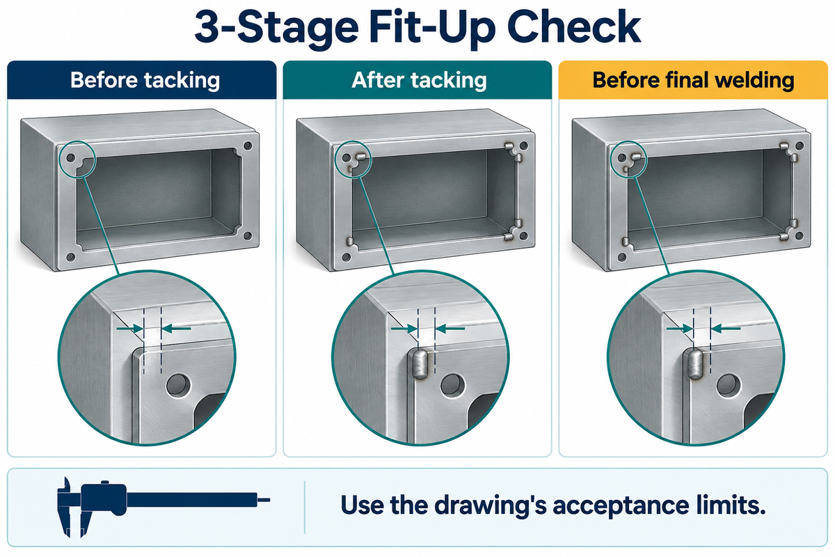
The 3-Stage Fit-Up Check compares the same critical dimensions prior to tacking, after tacking, and prior to final welding.
Illustrative shop scenario: A fabricator is assembling a rectangular enclosure whose door must close without binding. While the panels of the enclosure are clamped, the measurements of the diagonals look okay. Rather than just check the visible weld bead, the operator measures the door opening and hinge alignment. After tacking, the same measurements are made and supports retained, unless the process states otherwise. If the opening has moved, the team adjusts the fit-up before completing the seam. The final check is made using the acceptance limits drawn on the blueprint. This example describes a measurement method, and not a SIMITCH trial or a suggested tolerance; the important part is documenting the change.
There are also chemical limitations to surface preparation. ATSDR’s phosgene fact sheet cites welding metal cleaned with chlorinated solvents as an exposure route. Check cleaner compatibility and residues prior to heating. Short arc time isn’t a reason to forego fume controls. UK HSE guidance covers welding-fume controls even for small amounts of welding.
Tack weld size, spacing and joint gap
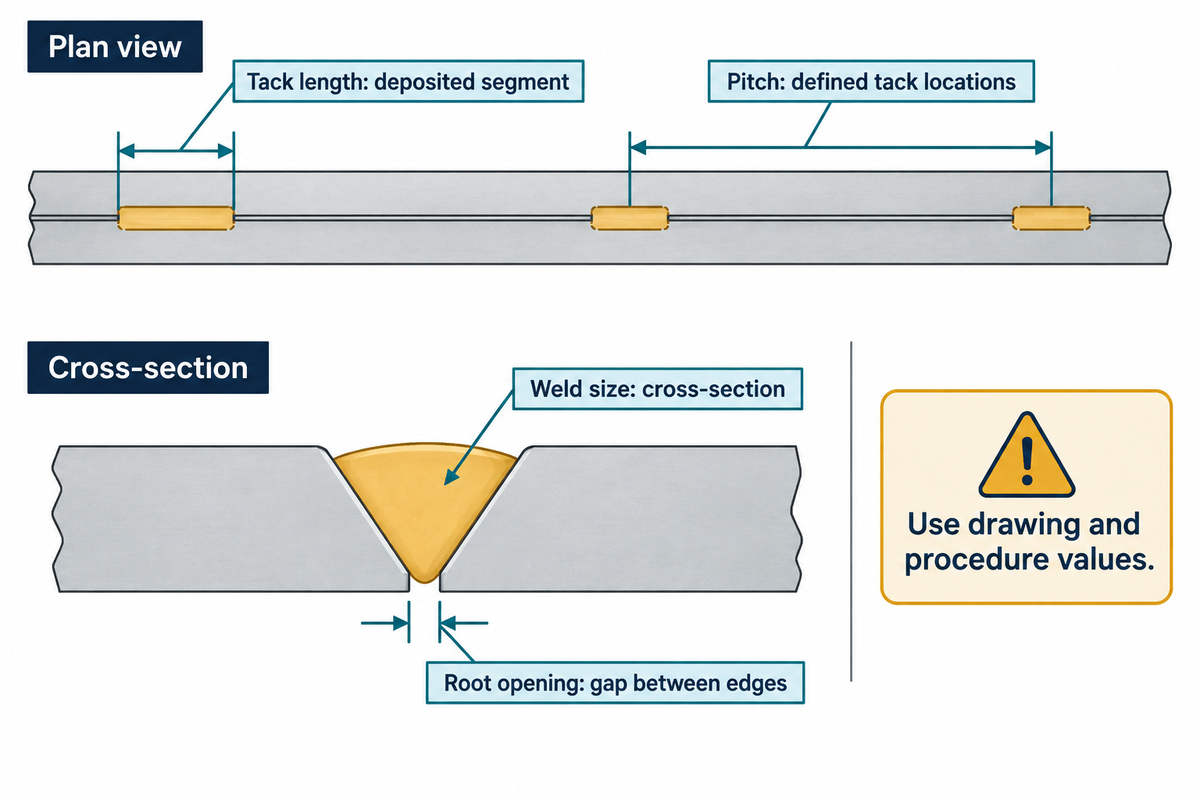
Tack length measures the deposited segment, weld size defines its cross-section, and tack spacing locates adjacent segments. Root opening defines the gap between joint edges. Keeping these dimensions distinct prevents a common drawing error: applying a spacing recommendation to the gap that the final welding procedure must bridge.
What is the usual gap of tack weld?
Root opening and the distance between tacks are different dimensions; neither has a single usual value for every tack weld. If “gap” means root opening, then use the joint preparation and welding procedure. If it means the distance between tacks, then use the tack layout. Confirm which dimension is meant before setting the fixture. The same number can’t safely answer both questions.
| Dimension | What it measures | Where the requirement comes from |
|---|---|---|
| Tack length, mm or in. | Length of an individual deposited segment | Required restraint and final-weld treatment |
| Weld size, mm or in. | Specified cross-sectional size | Joint design and applicable procedure |
| Pitch, mm or in. | Spacing between defined tack locations | Drawing or fabrication plan; define measurement convention |
| Root opening, mm or in. | Separation between mating joint edges | Joint preparation and welding procedure |
The Foundation design file makes a distinction between tacks intended for remelting and those embedded in the root. Their preferred geometries may be different. “Make every tack as small as possible” therefore leaves out the final-weld requirement.
Engineering Note
Record nominal dimensions and permitted variation from the actual drawing. Keep root opening, mismatch and tack pitch in separate fields. For structural-steel work using AWS D1.1, identify the contract edition and qualified procedure; a generic internet spacing table isn’t a substitute for either.
Tack welding sheet metal and different materials
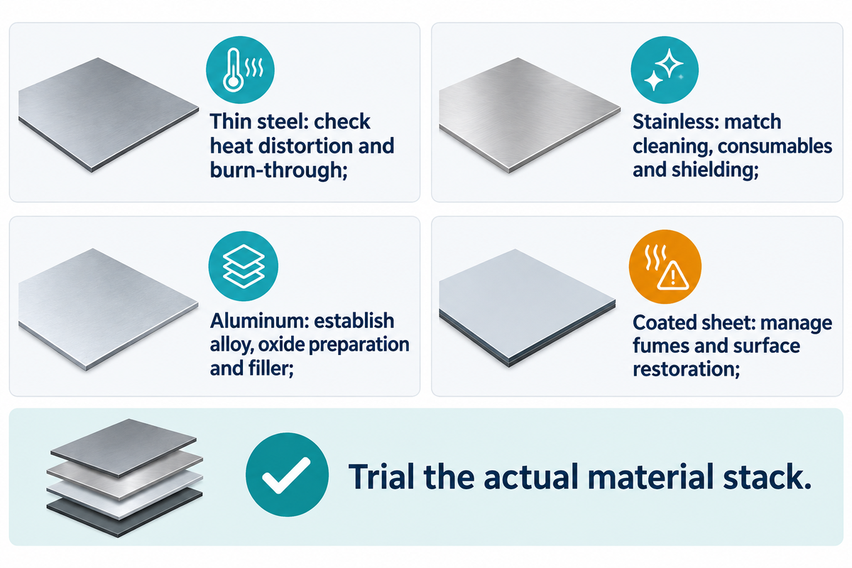
Thin sheet metal requires control over heat input and fit-up because burn-through or distortion can spoil the part before final welding begins. Uneven shrinkage can result in a panel being warped even though each individual attachment holds. Depending on the alloy and the condition of the surface, process requirements can be different. In general, process settings shouldn’t be transferred from one sheet to another simply because the thickness of the sheets is the same.
| Workpiece | Main question | Sample check |
|---|---|---|
| Thin steel sheet | Will local heating distort the panel or burn through? | Check fit-up, backside condition and finished geometry |
| Stainless steel | Are cleaning, consumables and shielding suitable for the grade? | Inspect the specified finish and joint quality |
| Aluminum | Are alloy, oxide preparation and filler choice established? | Use the actual alloy and thickness in the trial |
| Galvanized or painted sheet | How will coatings, fumes and corrosion protection be managed? | Include preparation and post-join surface treatment |
OSHA’s welding hazard guidance mentions zinc oxide associated with galvanized steel and zinc-rich paint. Its welding-fume fact sheet also states that outdoor or open work doesn’t mean there’s sufficient ventilation. Controls for the process should be based on the actual operation being done, including repeated short welds.
Illustrative finish-sensitive scenario: A sheet-metal supplier is quoting a coated cabinet panel with a visible exterior face. Welding can hold the components together, but the quote needs to consider the cost of surface preparation, thermal marking, and restoration of corrosion protection. If the design permits an adequate overlap and provides space for opposing tools, a cold mechanical joint could be worth a sample. If the cabinet instead requires a continuous sealed seam, isolated mechanical points don’t automatically provide that function. Purchasing should compare acceptable finished panels, including sealing and appearance, rather than comparing the time needed to make a single attachment. The sheet metal fastening guide develops that broader selection question.
Tack weld vs spot weld, clinching and riveting
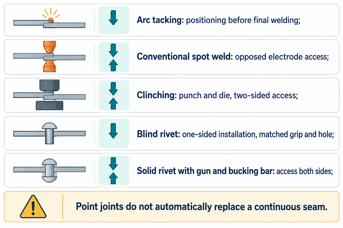
Tack welding can hold an assembly for subsequent welding; resistance spot welding, clinching and riveting can make the final connection. Choose among them by function of the seam, geometry and requirements of service and access. A process that joins two pieces of metal together at isolated points does not automatically replace a continuous weld.
| Route | Joining mechanism | Access and main limitation |
|---|---|---|
| Arc tacking followed by welding | Local fusion holds alignment before completion | Torch access, shielding and subsequent weld path must remain available |
| Conventional resistance spot weld | Resistance heat and electrode force form a local joint | Opposed electrodes need access; material stack and current path matter |
| Clinching | Punch and die plastically interlock overlapping material | Two-sided access and a suitable formable stack are required |
| Blind riveting | A selected rivet fastens a prepared joint | Installation can use one-sided access; grip and hole requirements still apply |
| Solid riveting with gun and bucking bar | The rivet shank is upset to secure the parts | Access is needed on both sides for the stated tool arrangement |
TWI’s tack-versus-spot explanation separates positioning from resistance welding. The opposed-electrode qualification in the table is deliberate. 2014 research published in the Quarterly Journal of the Japan Welding Society demonstrated a specialized indirect process with single-side electrode access. Its settings aren’t general shop practices.
The public DVS/EFB 3420 clinching summary describes a punch-and-die process of joining that eliminates the requirement of a separate joining element, namely, a rivet. The need for tooling and validation isn’t eliminated. EAA’s riveting guidance describes the access distinction between blind and solid riveting.
Illustrative access scenario: An enclosure has a rear cavity that becomes inaccessible after its last panel is installed. The team first checks whether the assembly order can preserve tool access. If it can, opposed-tool joining is still a possibility. If it can’t, a suitable blind fastening route may be worth evaluating. When assessing blind fastening, the team considers several constraints, including load direction, corrosion environment, seal, and permitted head projection. A static pull test alone does not validate a joint against fatigue or leak requirements. Before replacing a weld, the designer also assesses whether the part envelope is changed by the proposed modification. Sample requests should preserve the above constraints so quotations address the same finished part.
SIMITCH’s clinching machine range and riveting equipment range provide routes to investigate once the joint requirements are defined. Its self-piercing riveting systems are a separate equipment category from a hand-installed blind rivet.
Tack weld defects, inspection and removal
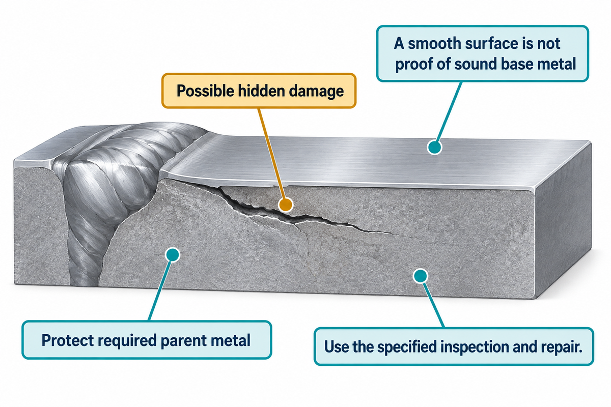
Prior to being covered by subsequent weld metal, check tacks for evidence of cracking, porosity, poor profile, misalignment, inadequate fusion and other defects using the inspection method required for the job. Other forms of non-destructive testing may be used to evaluate the quality of the joint when visual inspection cannot readily detect underbead cracks. A neat surface is useful evidence of appearance, but it cannot establish every internal quality requirement.
How to remove tack welds?
Approved methods of removing a tack include grinding. Make sure to protect the base metal, and then inspect the adjacent area. Stop before the required parent metal is removed. A tack that contains a crack or other defects must receive the specified repair. Just because the surface of the material appears to be sound doesn’t mean that the parent metal is sound.
The National Board’s historical technical article on tack welding and underbead cracking explains why surface removal can leave a damaged heat-affected region. That mechanism is pertinent to the present inspection; interpretations of historical code references shouldn’t be construed to be the project acceptance criteria.
Do
- Check the intended tack disposition before final welding.
- Remove slag and contamination as the procedure requires.
- Recheck geometry after permitted correction.
Don’t
- Hide a suspect tack under the final weld pass.
- Assume a flush surface proves sound base metal.
- Use a resistance-spot removal method without identifying the joint.
Where a tack is present, prepare its profile to allow the final weld to incorporate the tack as designed. Where a tack is removed, check the surrounding sheet and fit-up and ensure it’s sound before continuing. These are alternative inspection paths, and the shop traveler needs to define which path applies before the operator starts to finish welding.
Tack welding equipment and cost
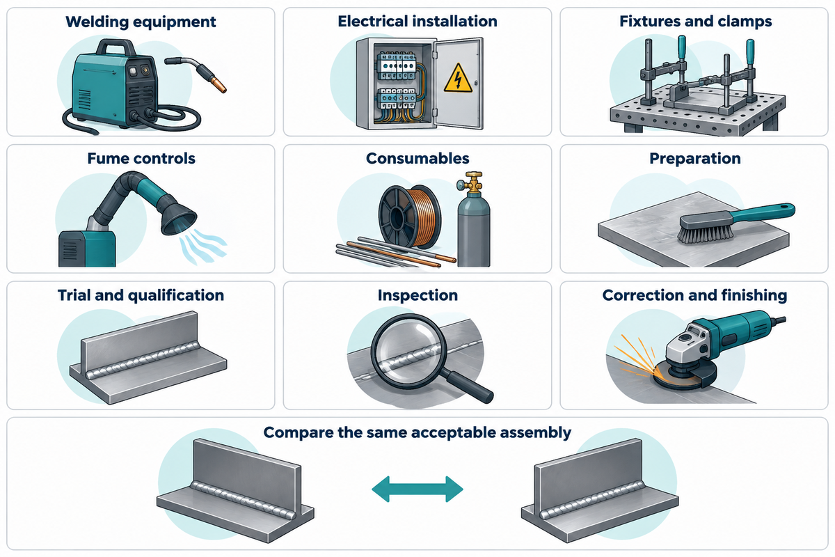
A suitable existing production welder may handle tacking, but locating, restraint, exposure controls and inspection must also be set up. Consider the cost of producing an acceptable assembly including correction and final welding. The purchase price of the equipment is only one element of this consideration.
A concrete retail reference is that Harbor Freight listed its TITANIUM MIG 140 welder, SKU 57863, at USD 499.99 on October 25, 2026. The listing is for a 120V welder. The listing specifies 120 V input and notes that welding wire is sold separately. This listing is for one US equipment offer, not an installed workstation estimate or an assembly recommendation.
Jim Worman’s National Board discussion of welding-process economics explains how inexpensive stick welding equipment can still have higher operating cost because of interruptions and consumable handling. The article is from 2013, and older price figures aren’t shown here.
| Cost item | What to specify | How to compare offers |
|---|---|---|
| Welding equipment | Process, material range and duty requirements | Compare the same intended production task |
| Electrical installation | Available supply and equipment requirements | Separate site work from machine supply |
| Fixtures and clamps | Datums, access and changeover needs | Include tooling for the actual part family |
| Fume controls | Workplace exposure assessment | Include extraction and required protective equipment |
| Consumables | Wire, electrodes, gas and wear parts | State what the initial package contains |
| Preparation | Cleaning and coating treatment | Count the work needed before the arc starts |
| Trial and qualification | Representative material and acceptance basis | Identify sample and validation responsibilities |
| Inspection | Fit-up, weld quality and finished dimensions | Include required gauges and inspection time |
| Correction and finishing | Tack removal, rework and surface restoration | Use measured shop results when estimating recurring cost |
When considering faster welding equipment, check where the assembly actually waits. Use the following map to decide what to evaluate on a given run; the map shows possible constraints, not measured improvements in cycle time.
| Stage | Delay signal | Check before changing equipment |
|---|---|---|
| Locate and clamp | Repeated adjustments before the first tack | Measure setup time; check datum access and fixture repeatability |
| Tack and recheck | Opening or alignment moves after attachment | Record dimensional change and correction time |
| Complete the weld | Tack position or profile interrupts the planned pass | Check integration with the final procedure and tool path |
| Inspect and finish | Parts wait for correction, grinding or coating restoration | Record acceptance failures and finishing time separately |
A welding helmet belongs in the safety equipment plan, but it doesn’t replace fume extraction. Similarly, a MIG welder quotation does not automatically include shielding gas or a part-specific fixture. Make explicit what’s included in each quote before totaling. For an alternative press route, SIMITCH’s pneumatic-hydraulic and servo press page distinguishes documented product families from an engineering-defined servo configuration.
Tack welding industry outlook and procurement checks
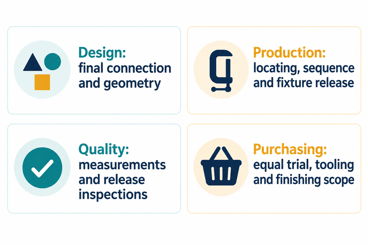
First, review the specified standard edition and consider the impact of the proposed production method on fit-up. Automation makes repeatable part presentation especially valuable, but it does not remove joint design or inspection requirements. Consider how process misalignment and variation would be handled and don’t solely trust the reported process cycle time.
The American Welding Society’s public D1.1 overview lists D1.1/D1.1M:2025-AMD1 and describes updates involving qualification, inspection and material references. One reason to identify the edition in the contract for work within its scope is to capture these types of changes.
For a new assembly, provide the supplier with the drawing, the actual material and coatings, an access envelope and acceptance criteria. Is a seal or a joint that carries cyclic loads and/or a joint that maintains a visible surface required? A sample should be made from the representative material stack; a change in material after the sample can impact the outcome.
- Design: define the required final connection and permitted geometry.
- Production: establish locating, tack sequence and allowable release of fixtures.
- Quality: specify the measurements and inspections that release the assembly.
- Purchasing: compare the same trial, tooling, installation and finishing scope. For a press-based alternative, use the servo press quotation checklist to organize the required inputs.
To use tack welding, understand what needs to be constant during the final welding process. If a new mechanical route is being considered, evaluate the entire assembly sequence before replacing isolated operations. A consistent weld starts with a repeatable setup; a mechanical joint needs an equally explicit acceptance plan.
Tack welding FAQ
These welding basics address process and drawing questions that are raised after the joint layout is finalized. The foundation design guidance clarifies the intent of the tack, while the implemented procedures control the actual work.
Can tack welds be permanent?
Yes. An acceptable tack may become part of the finished weld.
The procedure determines whether it remains, is remelted or must be removed. A tack left outside the finished joint needs its own specified disposition. Calling it temporary doesn’t exempt it from quality requirements. Nor does leaving it in place turn an incomplete joint into the permanent weld shown on the drawing.
Can you tack weld aluminum?
Aluminum can be tack welded with a process and preparation suited to its alloy and joint.
Identify the actual grade, thickness, oxide condition and required shielding before setting the equipment. Filler selection also follows the procedure. Use representative material for a trial, and inspect the resulting fit-up and joint quality. A setting that works on steel isn’t an aluminum procedure.
Can you tack weld galvanized steel?
Yes, with the required coating preparation and welding-fume controls.
The zinc coating changes both the exposure assessment and the finishing plan. Address coating removal where required, capture fumes and establish any necessary additional protection. A brief tack still heats the surface. Include restoration of corrosion protection in the job scope instead of treating the visible attachment as the finished result.
Can you tack weld with stick?
Stick welding can make tacks where the material, electrode and procedure are suitable.
Remove slag and inspect the deposit before subsequent passes. Thin sheet can be difficult to control with this process, so choose equipment for the joint rather than convenience alone.
What is a bridge tack weld?
A bridge tack spans a joint opening to hold the parts during fit-up.
The term describes a configuration, not a permitted gap or universal procedure. Establish its location and removal before final welding so it doesn’t obstruct the required root. A deposit that bridges the gap isn’t proof of acceptable fusion beneath it. Among types of tack welding, shop terms such as bridge tack or hot tack should be clarified against the actual procedure rather than treated as standardized machine settings.
What does a tack weld symbol mean?
A tack instruction identifies positioning welds; the complete drawing defines their dimensions and treatment.
Read the referenced symbol standard and drawing notes for length, spacing, acceptance criteria and removal.
Can you tack weld with TIG without gas?
Conventional TIG welding needs shielding gas to protect the electrode and weld area.
A brief tack doesn’t remove that requirement. Gas flow and any root protection follow the material and procedure. If a description promises welding without gas, identify whether it refers to a different process or a specialized environment. An attached small weld isn’t evidence that the weld pool was adequately protected or that oxidation is acceptable.
Evaluate the joint before choosing the machine
Send SIMITCH your drawing, material stack, coating and access constraints to discuss a clinching or riveting route for the assembly.
Older technical sources describe mechanisms; recent project specs determine procedures and acceptance. Supplier information and the dated retail price are attributed to their respective authors.
References & Sources
- Pay Attention to Tack and Temporary Welds — James F. Lincoln Arc Welding Foundation, Duane K. Miller.
- How to perform a successful tack weld — The Fabricator, Elia Levi.
- Preventing and correcting weld material distortion — TWI.
- Phosgene ToxFAQs — Agency for Toxic Substances and Disease Registry.
- Welding fume: protect your workers — UK Health and Safety Executive.
- Welding hazards — US Occupational Safety and Health Administration.
- Controlling hazardous fume and gases during welding — US Occupational Safety and Health Administration.
- Tack weld versus spot weld — TWI.
- Single-side resistance spot-welding research — Quarterly Journal of the Japan Welding Society, 2014.
- DVS/EFB 3420 public summary — DVS Media, April 2021.
- Rivet Gun Notes and Riveting Tips — Experimental Aircraft Association, Tony Bingelis, 1988.
- Tack Welding — National Board of Boiler and Pressure Vessel Inspectors, Michael J. Houle, 1980.
- What is the Best Welding Process? — National Board, Jim Worman, 2013.
- D1.1 Structural Welding Code: Steel overview — American Welding Society.