Get in touch with Suzhou Simitch Machinery Co., Ltd Company

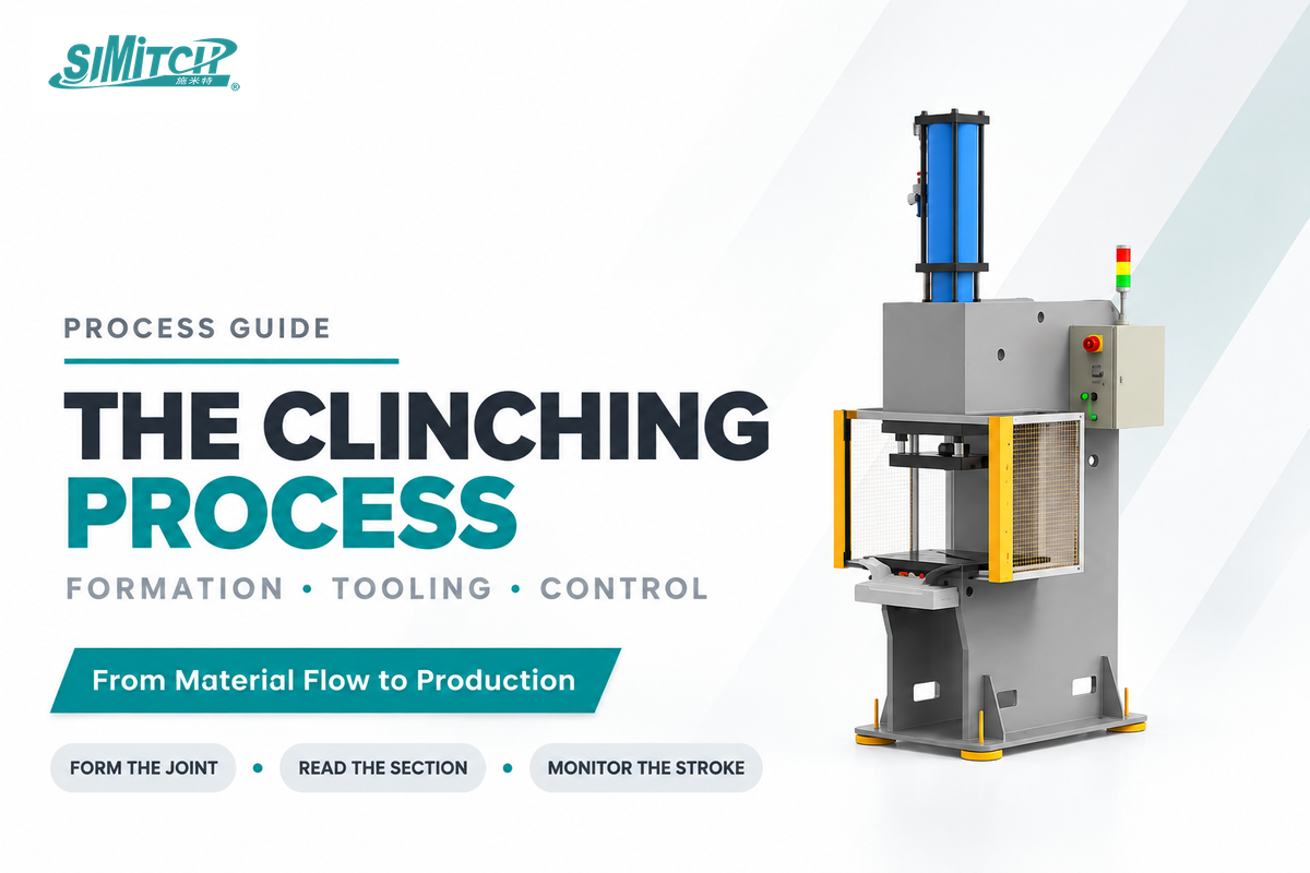
The clinching process is a type of metal joining method that forms a mechanical interlock with a punch and die. No additional rivet or screw is added. A useful question for production is to examine how the tooling moves the material, what’s contained within the joint, and what measurements reflect a change.
Key takeaway
The clinching process is a cold-forming joining method. A matched punch and die deform overlapping sheets into a retained interlock. Joint qualification combines section geometry with application-specific tests; production monitoring compares each stroke with a qualified reference.
Process at a glance
- A normal-looking button can conceal a thin neck or limited interlock.
- Conventional non-cutting clinching forms the sheets without welding heat or an added fastener.
- The key section features are neck thickness, undercut and residual bottom thickness.
- Force and displacement describe the forming stroke; service tests address the assembly’s loads and environment.
What Is the Clinching Process?
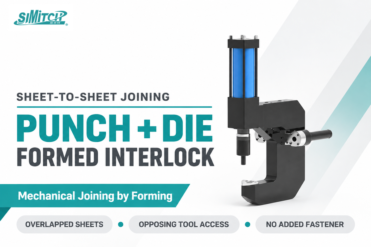
Clinching is a mechanical joining process that locks sheets together through localized plastic deformation. To understand this better, think of pressing nested pockets into the sheets, and spreading the material situated beneath the pocket’s narrow opening. The resulting undercut resists separation. A conventional round, non-cutting joint uses the sheets themselves as the connection rather than inserting a fastener.
Both sides of the joining location normally need tool access: the punch acts from one side and the die supports the other. The DVS 3420 clinching bulletin describes this joining-by-forming principle and covers component design, suitable metallic materials, technology and quality assurance.
Self-clinching hardware, a different mechanical fastening operation, incorporates a captive nut, stud or similar element into a prepared sheet. Keeping these processes separate allows a tooling engineer to identify if the intended connection is sheet to sheet or hardware to sheet.
Automotive applications include brackets and other sheet assemblies. For metal joining applications in appliance manufacturing and HVAC fabrication, the available flange and required load path govern whether clinching fits the part. The joint leaves a local recess and projection, so a flush visible face needs attention during component design.
How the Punch Forms an Interlock in 4 Stages
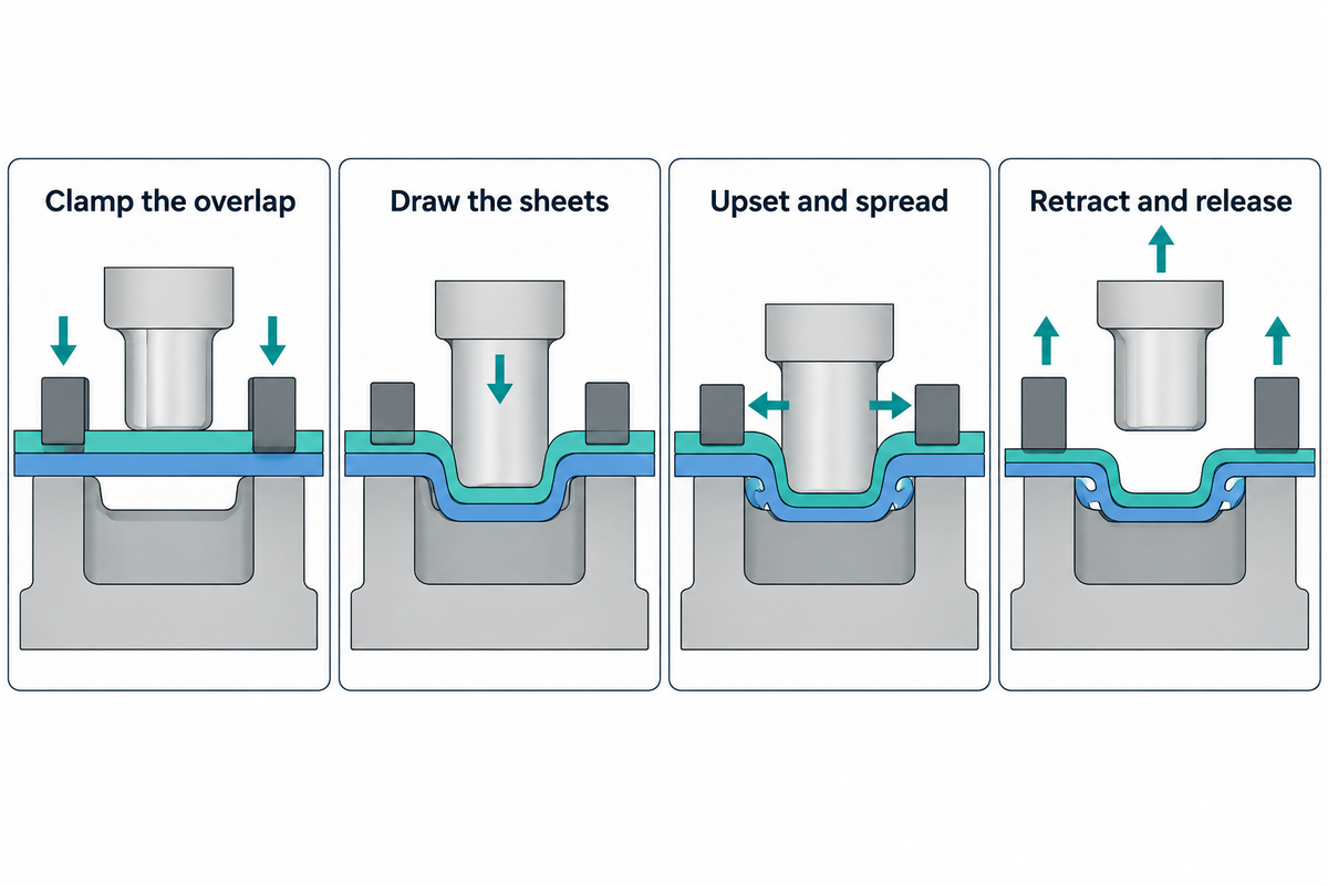
Four events describe the operation of a conventional clinching stroke. The first is clamping; the second drawing; the third upsetting; and the last is release. Material is continuously in motion. The punch drives the stack into the die; the constrained material then flows sideways. The tool withdraws and the sheets retain one another.
- Clamp the overlap. The blank holder or stripper restrains the sheets around the joining point. Its support affects how material feeds into the forming zone.
- Draw the sheets. The punch advances into the supported stack. Both metal sheets deform, and a pocket develops inside the die.
- Upset and spread the material. Continued compression redirects material into the available cavity. The upper sheet develops an undercut within the lower sheet. Neck and bottom regions become thinner as the shape develops.
- Retract and release. The punch returns and the stripper separates the workpiece from the tool. Withdrawal clearance matters as well as the space needed to reach the joint.
The design affects how the material flows. A fixed cavity constrains flow with stationary walls; a segmented die permits its moving elements to open during formation. Clinching technology also includes cutting or semi-cutting variants with different sheet paths. Their joint shapes and sealing behavior differ from the non-cutting round example.
The 2017 review, Clinching for sheet materials, describes tooling and process variants. It links tool geometry to the balance between neck thickness and interlock. Extra stroke changes that balance; it isn’t simply an extra amount of fastening strength.
Read the Joint with the 3-Feature Clinch Section
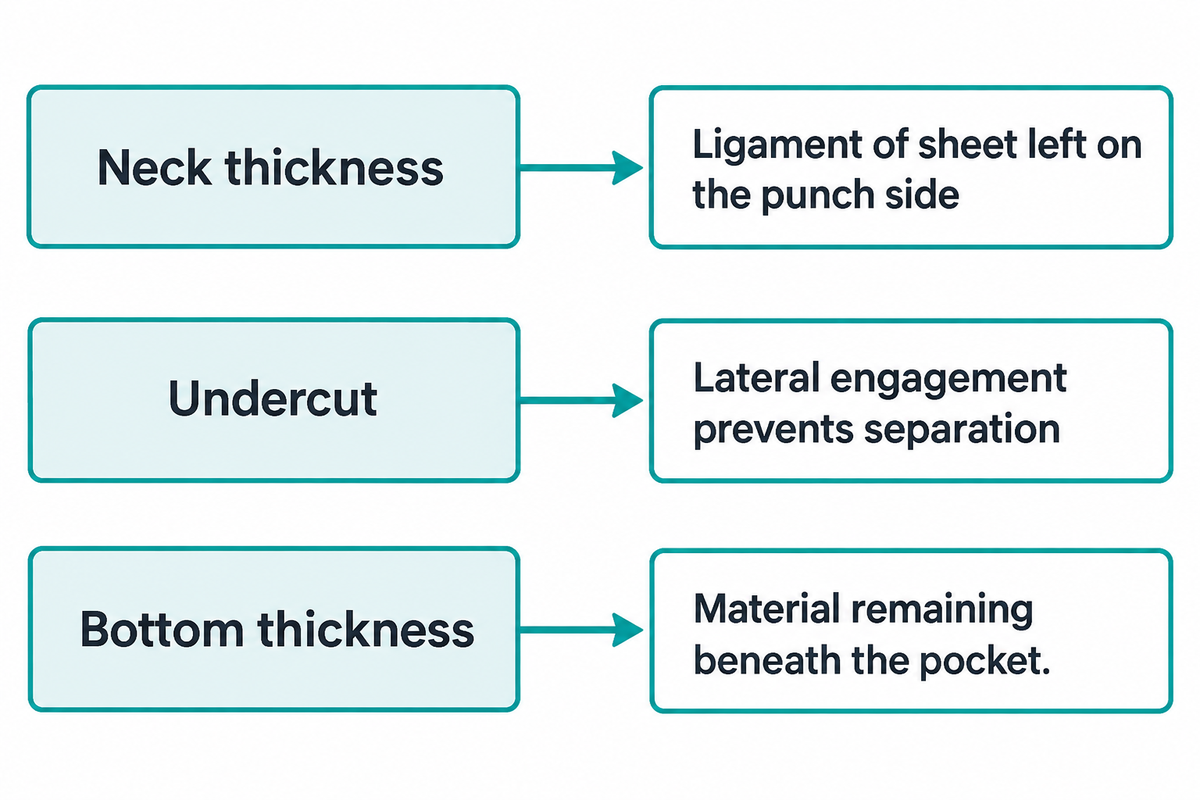
The 3-Feature Clinch Section is a way to read a prepared joint section: locate the neck, trace the undercut, then measure the residual bottom. With these observations, the next comparison or test can be chosen. An external button diameter sometimes defines part of the shape, but can also hide an internal asymmetry.
Neck thickness is the ligament of sheet left on the punch side, and the Undercut is the lateral engagement that prevents formed sheets from separating. Bottom thickness describes material remaining beneath the pocket. While they explain how the joints are formed, the acceptance values belong to qualified material and tooling.
| Feature or observation | What it can indicate | Next comparison |
|---|---|---|
| Thin punch-side neck | Limited ligament available to carry load | Compare section and fracture location with the qualified joint |
| Small undercut | Limited mechanical engagement | Examine opening or pull-out behavior |
| Changed bottom thickness | Different final forming condition | Compare stroke, stack and section together |
| Unequal necks across a section | Asymmetric material flow | Inspect alignment and examine another section plane |
| Unequal engagement around the joint | Local rather than uniform interlock | Compare additional section orientations |
| Crack through the neck | Forming damage or neck fracture | Separate as-formed cracks from damage created during testing |
| Button pulls out during loading | Interlock opens or disengages | Relate failure to load direction and measured undercut |
| Mixed tearing and opening | Combined failure behavior | Record both mechanisms rather than one defect label |
| Intact visible projection | External shape retained | Inspect the internal section and relevant mechanical performance |
Neck fracture and button separation are useful starting categories. The 2019 failure-mode study also identifies hybrid modes. A quality engineer therefore records where the material tears and how the interlock opens, rather than treating every failed joint as an undersized button.
Section orientation matters when alignment is suspect. One cut can miss the weakest region of an eccentric joint. A consistent preparation and measurement method makes changes in the mechanical properties of clinch joints easier to interpret.
Choose Clinching Tool Geometry for Material Flow
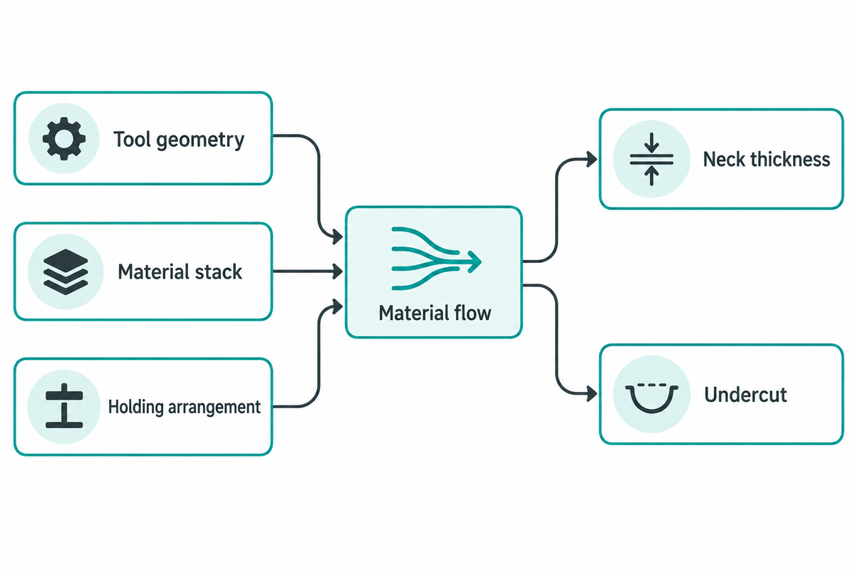
A matched punch, die and holding arrangement should be provided, for the given material stack and available access. The depth of the die, and the shape of the cavity affect where the sheets are thinned, and where the interlock forms. Total stack thickness is a starting description; it does not capture the ductility, surface condition or order of the layers.
What is a sheet metal punch?
A sheet metal punch is the tool that applies local force to form or cut a sheet against supporting tooling. In conventional clinching, the punch forms a pocket and guides the material into a matched die. A hole-punching tool shears material to create an opening, so its clearance rules aren’t a clinching recipe.
The tooling designer balances the engagement against the remaining neck material when selecting the geometry and process parameters. The tooling discussion in Nourani et al. identifies geometry and friction among the factors that influence clinch formation. Enlarging one feature may reduce another. For example, a larger punch tip radius changes the flow path and the neck/undercut balance described in the technical review. A fixed-wall and an extensible die may also require different clearance around the part.
Example: consider a formed HVAC channel with a joining flange inside the profile. The punch reaches the mark, but the die body contacts the adjacent wall before the flange sits flat. A more powerful drive doesn’t remove that collision. The tooling layout needs a suitable die envelope and support surface, followed by a withdrawal path that clears the formed button. Trialing flat strips alone would miss the access problem. Part drawings and the intended approach direction therefore belong in the tooling review before the press is selected.
Clinching tools are sold in families for different material and thickness combinations. BTM and Press Lock Technologies are examples of tooling suppliers. Their product-family names and catalogue limits belong to their own joining systems; swapping a similar-looking punch into another die can change the joint geometry.
Material Stack, Coating and Sheet Order
A formable sheet material must withstand the local drawing and upsetting required to create an interlock. A number of factors including grade, thickness tolerance, coating, sheet order, and previous forming affect this response. Mild steel and aluminum may offer workable combinations, while a harder or less ductile layer can restrict the selected conventional clinching geometry.
The Nourani et al. tolerance and misalignment study used a 10:1 plasticine analogue, alongside an actual steel comparison with 1.2 mm and 0.8 mm sheets. Tolerance and angular misalignment reduced interlock in the analogue experiments. The dimensions of the models show sensitivity; the metal stack requires its own tool-and-material evaluation.
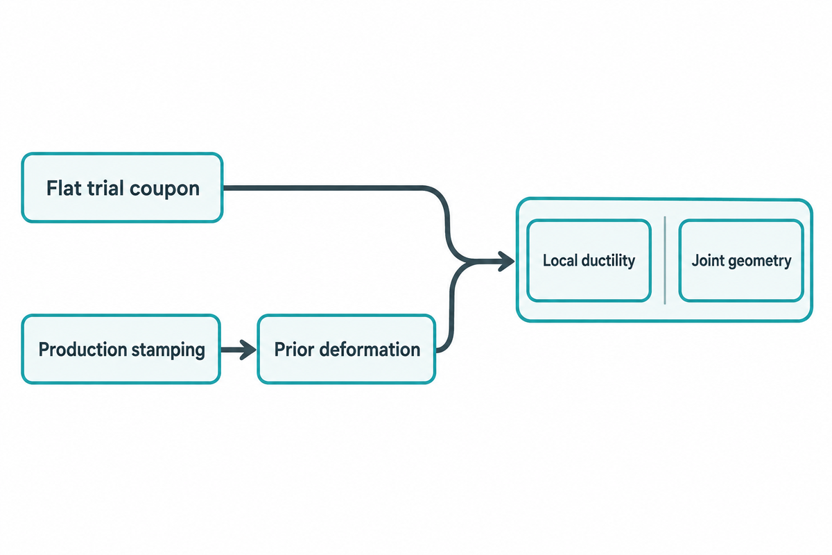
Prior deformation is another variable. A 2022 study of joint and component interactions examined HCT590x steel at 1.00 mm and 1.51 mm thickness. Pre-stretching changed joint geometry and failure behavior. Two parts made from the same nominal steel sheet can arrive at the joining station with different local ductility after forming.
Example: an appliance panel supplier replaces a flat trial coupon with a production stamping. The joining flange has already been stretched near a drawn corner. The same tool now forms a thinner neck locally, even though the material certificate and nominal thickness match. The engineering comparison uses coupons taken from the formed region as well as the original flat stock. Changing the coil specification alone would leave the upstream forming effect unresolved.
Joining dissimilar sheet metals also introduces surface and environmental questions. A galvanized coating and a pre-painted surface respond differently to local deformation. Cold-forming avoids a weld’s local heat input, but stretched coatings can still crack. For joining of dissimilar metals, corrosion exposure and the surrounding protective system remain part of the assembly design.
Test the Clinch Joint for Its Load Case
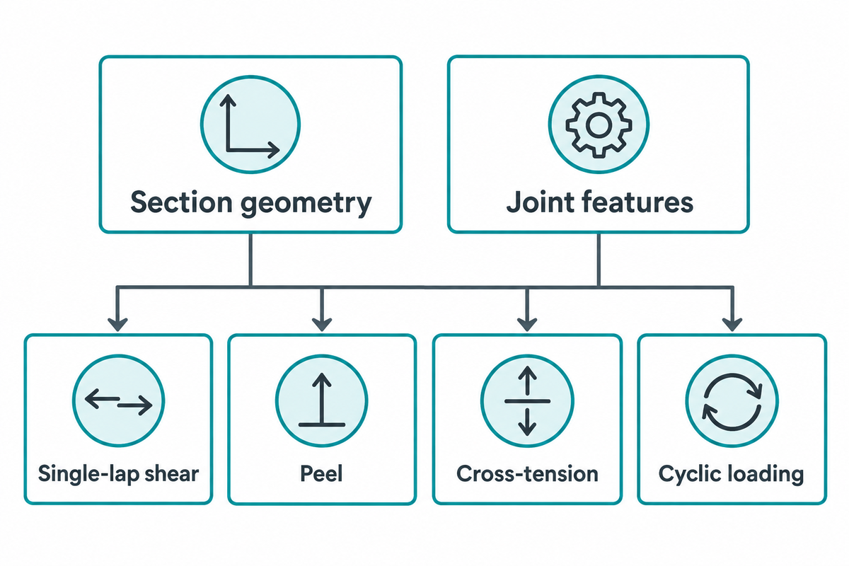
Test the joints with the loading conditions and environment the assembled structure will experience. Single-lap shear tests address one loading arrangement; peel, cross-tension or cyclic tests answer different questions. A section explains the formed geometry, while a mechanical test measures behavior under its stated fixture, loading rate and failure criterion.
How do you know a clinched joint is strong enough?
A clinched joint is strong enough when its qualified performance meets the assembly’s specified loads and failure criteria. Start with the load direction and service conditions required, and connect joint measurements to representative tests. Peak shear strength, alone, leaves opening behavior, displacement at failure, and repeated loading, unresolved.
During tensile shear testing, record more than the largest load. Load-displacement behavior and fracture location help distinguish a joint that opens from one that tears through the neck. Comparison of shear and tensile loading also explains the need for a stated specimen and load direction for a joint that’s claimed to be “strong.”
For fatigue testing, Spak et al. fatigue investigation focused on EN AW-6060 T66 joints. Results indicate material response and scatter influence fatigue predictions. Its results concern the tested variants, rather than a universal strength ratio to welding.
There are other interactions for wet and corrosive service conditions. For example, a 2025 pitting-corrosion investigation covered EN AW-6014 and includes observations from aluminum/galvanized-steel joints that were pre-corroded and fatigue loaded. The duration of exposure and the mechanism of corrosion (or other service related damage) contribute to the response of a system. Environment and cyclic loading belong together in the validation plan for an exposed assembly.
A battery housing flange may also need a separate sealing function, while an electrical connection needs suitable resistance and durability testing. The load-bearing capacity of clinched joints addresses only part of either requirement.
Control Production with Force and Displacement
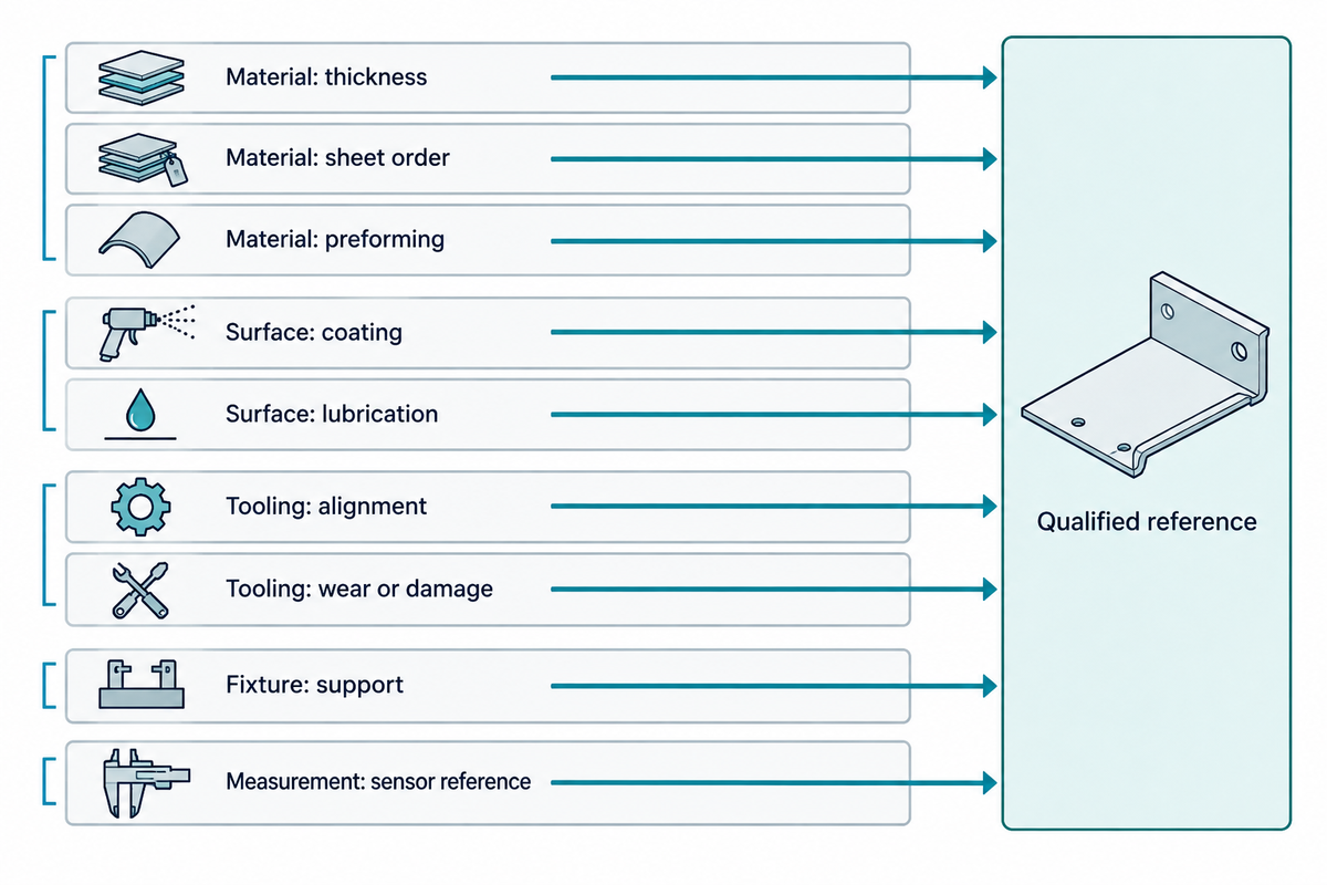
Production monitoring compares the force and displacement of punches with a reference established on satisfactory joints of the relevant stack. The curve shows how the forming process develops. Measurements and tests establish relationships between process behavior and the joint features that are critical to the application.
“The width of this acceptance range can be altered to suit the requirements of specific applications.”
Reference windows require the correct stack identity, tooling and measurement arrangement. Changing a material batch, lubricant or support condition can shift the curve. Widening a window simply to accept the new signals would be useless since the comparisons made during monitoring would no longer be valid.
| Change class | Possible process change | Useful investigation |
|---|---|---|
| Material: thickness | Different contact and forming progression | Measure the stack and compare the section |
| Material: sheet order | Different flow between punch and die sides | Check layer identity and engagement |
| Material: preforming | Different local ductility or work hardening | Compare production parts with flat coupons |
| Surface: coating | Changed friction or local coating response | Inspect coating condition and geometry |
| Surface: lubrication | Changed forming resistance | Compare surface condition and load-stroke behavior |
| Tooling: alignment | Unequal flow around the point | Inspect alignment and multiple section planes |
| Tooling: wear or damage | Changed cavity or punch contact | Inspect the tool and compare joint features |
| Fixture: support | Part motion or local bending | Check seating and support at the joining position |
| Measurement: sensor reference | Apparent curve movement without equivalent joint change | Check the measurement reference and retained samples |
Example: a high-speed production station begins rejecting joints after a coil change. The team retains the suspect assemblies and compares material identity, thickness and sections with the last accepted batch. If the bottom thickness and interlock have changed, the curve shift may reflect a changed forming condition. If geometry and test behavior remain comparable, the measurement chain and surface condition still need investigation. The quality engineer makes the disposition using the agreed acceptance plan; an operator doesn’t erase the rejects by enlarging the window.
The 2022 lateral-offset study deliberately offset tools by 0, 0.1 and 0.2 mm in two 2 mm Al 6014 sheets. It distinguished process window monitoring and measurement of internal geometry. Its CT method used 0.01 mm tin foil to reveal the interface, a research contrast aid rather than an assembly ingredient.
EFB report 595 investigated additional near-joint sensing and model-based geometry estimation, but its public summary reports that prediction accuracy did not fully meet inline-monitoring requirements. A 2026 hybrid-design study combines rules and predictive models in two demonstration tasks; new material combinations and production drift need additional validation. For routine equipment care, see the portable clinching maintenance guide.
Clinching vs Spot Welding and Riveting
Use clinching as a metal joining method when the sheets are able to create an adequate interlock and the part allows access for a punch and die. Resistance spot welding forms a local metallurgical connection through electrical heating; self-piercing riveting adds a rivet that flares into the lower sheet. Each joining technology has different material, access and consumable requirements.
| Design question | Clinching | Resistance spot welding | Self-piercing riveting |
|---|---|---|---|
| Connection mechanism | Formed sheet interlock | Weld nugget | Flared rivet and retained sheets |
| Added element per joint | No separate fastener | No rivet or screw | Rivet |
| Material response | Local formability governs flow | Electrical and metallurgical compatibility matter | Rivet penetration and lower-sheet deformation matter |
| Surface considerations | Coating stretches during forming | Local heat affects surface and coating | Coating responds to piercing and forming |
| Assembly checks | Section, loads and function | Weld quality, loads and function | Rivet setting, section, loads and function |
TWI’s comparison of mechanical joining and spot welding focuses on fitness for purpose. Thick organic coatings can affect mechanical joining as well. Joining dissimilar materials without heat avoids some welding constraints, but local formability and corrosion remain relevant.
A spot welded coupon and a clinched coupon need comparable specimens and load directions before their strengths can be compared. The strength of a weld varies with its material and welding condition, just as the strength of clinched connections varies with geometry and stack. For other joining techniques, the sheet metal fastening methods guide covers the wider metal assembly choice.
From Tooling Trials to a Production Setup
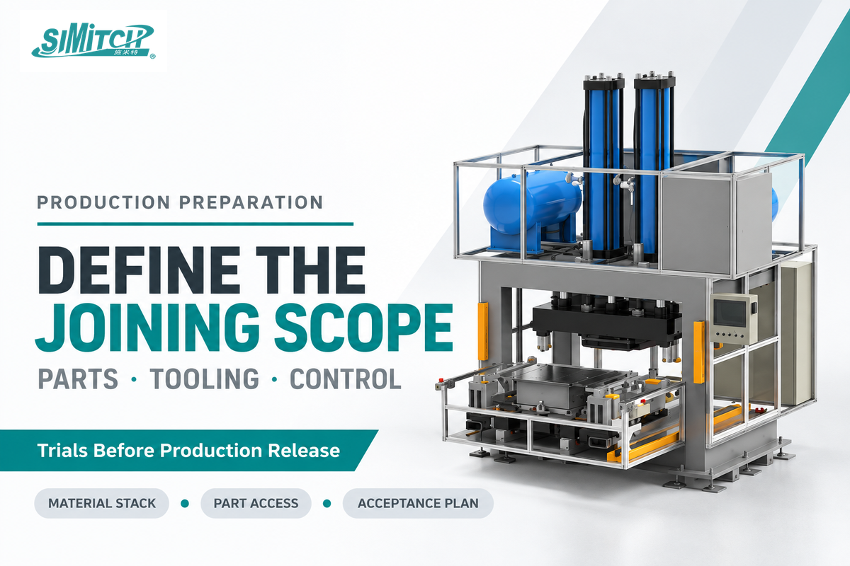
During production setup, use representative parts and known joint requirements, and connect tooling trials to the fixture and control plan. A punch and die pair and a monitoring press are different purchasing scopes from that of an integrated joining cell. Tooling costs and delivery also differ with those purchasing scopes rather than a common price per clinch. For equipment selection and joint approval, see the clinching equipment guide.
A useful quotation identifies standard or custom tooling, tool holders, access extensions, workholding and sample evaluation. Development time is spent in reaching an agreed joint configuration. Stock shipment of an existing tool is a separate milestone from the approval of a custom stack or commissioning of an automated cell.
Tooling suppliers and monitoring specialists
Tooling suppliers like BTM and TOX have their own tool families. Displacement/force measuring and evaluating equipment, and systems, are supplied by monitoring technology specialists. It’s the responsibility of a system integrator to assemble and integrate the required functions and controls with the press, fixtures and the production system. The mechanical performance of clinched assemblies still needs an agreed application test plan across those responsibilities.
Simitch supplies intelligent joining equipment and system solutions for automotive components, energy storage systems, photovoltaics, home appliances and HVAC applications. Its Pneumatic and servo-press options address different control and drive systems for manual and automated production.
For an application review, provide:
- Material grades, layer order, nominal thickness and tolerances, including coating and prior forming.
- Part drawings showing joint locations, flange widths, approach directions and withdrawal clearance.
- Load directions and required shear, opening, fatigue, sealing or electrical performance.
- Production sequence, rate, workholding and traceability needs.
- Acceptance measurements, representative samples and responsibilities for testing and release.
Process engineers can review Simitch clinching machines and joining-system options or send the material stack and part drawing to Simitch for a tooling and production discussion.
Frequently Asked Questions
Can clinching join coated or dissimilar sheets?
Yes, clinching can join metal sheets with suitable coatings and dissimilar material combinations.
Material formability and the selected tooling determine whether enough interlock develops without unacceptable cracking. Joining dissimilar sheets also requires attention to layer order and corrosion exposure. A pre-painted finish can stretch or crack locally even though the joining operation uses no welding heat. Coating condition, mechanical loads and any sealing function therefore belong to the application trials.
What are the disadvantages of clinching?
Clinching needs suitable sheet formability, tool access and space for the local joint shape.
The recess and projection can interfere with a visible surface or close-fitting assembly. Limited neck thickness or engagement can restrict performance in a particular load direction. Material or thickness changes may require another tool combination and evaluation. Compared with traditional welding, clinching avoids a weld cycle but introduces its own forming and inspection requirements. A joint layout should account for these constraints early.
Which drive types are used for clinching?
Pneumatic, hydro-pneumatic, hydraulic and servo-electric drives are used in clinching equipment.
The drive supplies the stroke and forming force; the matched tooling determines the local material flow. Servo control can support programmed motion and signal capture. Hydro-pneumatic systems combine pneumatic operation with a hydraulic force stage. Drive selection also considers duty, available utilities, installation space and the production control system. The joint still requires evaluation on its intended stack.
Can a clinched joint be taken apart?
A conventional clinched joint is intended as a permanent connection.
Separation usually damages the formed interlock or surrounding sheets. Removable assemblies generally need a fastening method designed for disassembly.
Is clinching the same as cold welding?
No. Conventional sheet clinching relies on a mechanical interlock.
Cold welding describes solid-state bonding between metal surfaces under suitable conditions. The absence of a welding heat source doesn’t make every cold-forming connection a cold weld. During sheet metal clinching, the punch and die create a shape that retains the layers. Some published work discusses local bonding effects in particular combinations, but the formed interlock explains the conventional process. This distinction also separates clinching from self-clinching nuts, where sheet material flows into a feature on an added fastener, and from self-piercing rivets, where the added rivet flares within the stack.
Can one tool set handle every sheet stack?
No. A tool set has an application range rather than universal stack compatibility.
Different materials, thicknesses and layer orders change how the material flows. A tool family may cover several qualified combinations, while another stack needs different geometry. A change in coating or prior forming can also require renewed evaluation.
References & Sources
- He et al., Clinching for sheet materials, 2017.
- Nourani et al., Multiscale Analogue Modelling of Clinching Process to Investigate Thickness Tolerance and Tool Misalignment, 2022.
- Failure modes of mechanical clinching in metal sheet materials, 2019.
- Characterisation of lateral offsets in clinch points with computed tomography and transient dynamic analysis, 2022.
- DVS 3420, Clinching: basics, 04/2021 public abstract.
- TWI, Monitoring the clinching process for quality assurance.
- TWI, Clinching and self-piercing riveting compared with spot welding.
- Analysis of the interactions between joint and component properties during clinching, 2022.
- Spak et al., Estimation of fatigue life for clinched joints with the Local Strain Approach, 2021.
- Numerical investigation of pitting corrosion in clinched joints, 2025.
- EFB research report 595, public project summary.
- A hybrid knowledge based and data based approach for efficient clinch joint design, 2026.