Get in touch with Suzhou Simitch Machinery Co., Ltd Company

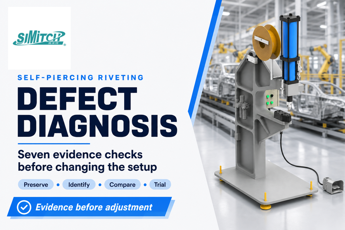
Self piercing riveting defects are usually diagnosed from related evidence. Preserve the original joint, record the top and die-side symptoms, and verify the material and tooling identities. Inspect a traceable section, compare the force-displacement signal, change one bounded variable, and confirm repeatability. Anomalies such as raised heads and cracked buttons provide clues. None identifies one universal cause by itself.
Seven checks before changing the setup
- Preserve the baseline joint and its production identity.
- Record the rivet-head and die-side condition.
- Separate an as-formed defect from a test failure.
- Verify sheet, adhesive, rivet, die, fixture, and recipe revisions.
- Measure a traceable section without treating one cut as the whole joint.
- Reconcile physical evidence with the process trace.
- Run a controlled trial and release only against project criteria.
Identify the Defect Before Changing the Riveting Process
Start with containment and observation. At least one suspect joint is kept unaltered and machine records and an approved baseline are kept. The identity of the part, lot, station, tool set, recipe change, time, operator, or automatic cycle is labeled. If a joint has been sectioned or tested mechanically, say so. Lack of original evidence is an unknown, not a pass.
Why are my rivets not working?
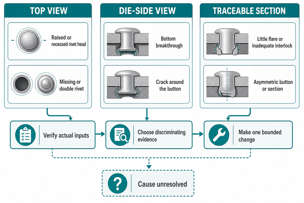
Self-piercing rivets can appear wrong because of a change in the material stack, mismatch of the rivet or die, shifted sheets, unsupported joint, or process drifting. Symptoms can be a result of different root causes. Inspect both sides of the joint, check the actual inputs, and choose the next check that separates competing explanations before changing force or position.
| Defect type or observed condition | Competing explanations | Discriminating evidence | Bounded next step |
|---|---|---|---|
| Raised or recessed rivet head | Stack thickness, rivet length, material response, die support, or endpoint drift | Actual stack and rivet identity, head-height record, section, and trace comparison | Restore the verified input or trial one documented change |
| Little flare or inadequate interlock | Rivet, die, stack order, material condition, or incomplete formation | Centered section with dimensions tied to sample identity | Review the stack-specific rivet and die combination |
| Bottom breakthrough | Wrong combination, lower-sheet variation, alignment, or excessive penetration | Die-side photo, section, lower-sheet identity, alignment, and recipe | Contain the lot and reproduce under controlled inputs |
| Crack around the button | Local ductility, stack order, die geometry, coating, adhesive condition, or alignment | Crack location, material certificate, section, and named mechanical test | Escalate to the design authority; do not accept from appearance alone |
| Asymmetric button or section | Punch-die misalignment, sheet movement, fixture support, or off-center cut | Alignment check plus a documented section plane | Separate fixture alignment from section-preparation error |
| Missing or double rivet | Feed, presence sensing, sequence, or recovery logic | Part record, rivet count, feed history, and station event log | Contain affected parts and verify the detection sequence |
| Rivet buckling | Rivet selection, support, alignment, stack response, or instability during setting | Section orientation, rivet identity, tool alignment, and trace shape | Recheck the approved combination and alignment before a new setting |
| Sheet gap or separation | Part fit, fixture support, adhesive distribution, debris, or local distortion | Pre-join fit record, fixture check, section, and adhesive evidence if used | Correct the verified fit or support condition, then retrial |
| Trace drift with no sampled visual defect | Material or tool drift, sensor change, wrong baseline, or missed physical condition | Reference identity, sensor check, wider physical sample, and section evidence | Hold release until the signal change is explained |
The Welding Institute’s guidance asks inspectors to check both the top sheet and the die side, including head seating, cracks, distortion, button symmetry, and visible rivet tail. Its detailed-examination guidance adds section symmetry, head gap, interlock, and remaining material around the rivet foot. These checks address different questions. A visual inspection of the joint is a quick check; a section gives a more clear picture of the local internal geometry of the joint.
Decision rule
If there’s physical damage, contain and investigate it. If only the signal differs, confirm the part, material, tool, and recipe identities before interpreting the curve. If the original condition wasn’t recorded, label the cause unresolved instead of reconstructing certainty from a fracture surface.
Separate SPR Formation Defects From Test Failures
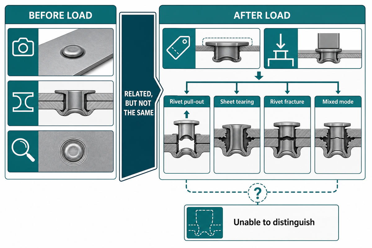
An as-formed defect exists when the rivet is set. A mechanical test failure describes how a defined specimen behaved under a named loading condition. The two may be related, but aren’t the same. For a self-piercing riveted coupon, the observed failure mode and joint strength are tied to named loading conditions. A pull-out, sheet tear, shear fracture, or rivet fracture after loading doesn’t necessarily indicate that the original joint had a defective head seat, poor interlock, or a cracked button. Conversely, an attractive section doesn’t necessarily mean that a specified strength or fatigue limit was achieved.
What failures can occur in riveted joints?
Joint type and loading condition affect whether a tested joint fails by rivet pull-out, sheet tearing near the rivet, rivet fracture, or a mixed mode. Record the specimen geometry, load direction, rate or cycle conditions, and the joint’s condition before loading. The observed mode belongs to that test and shouldn’t be considered for a universal defect list.
ISO 12996:2013, confirmed current in 2024, specifies specimen geometry and a tensile-shear test procedure for single mechanical joints. Its public scope supports consistent tensile testing, not a universal visual or cross-section acceptance limit. A separate study of button cracks in defined AA6008T61-bottom-layer stacks reported different effects in a lap shear test and T-peel tests. That result means the loading mode must stay visible in the report. It does not authorize button cracks.
When the before-load record is missing: classify the specimen as unable to distinguish formation condition from test-induced damage. Use another traceable sample or repeat the controlled test. Do not justify equipment replacement from one post-test photograph.
Check Sheet Materials Before Choosing a Rivet and Die
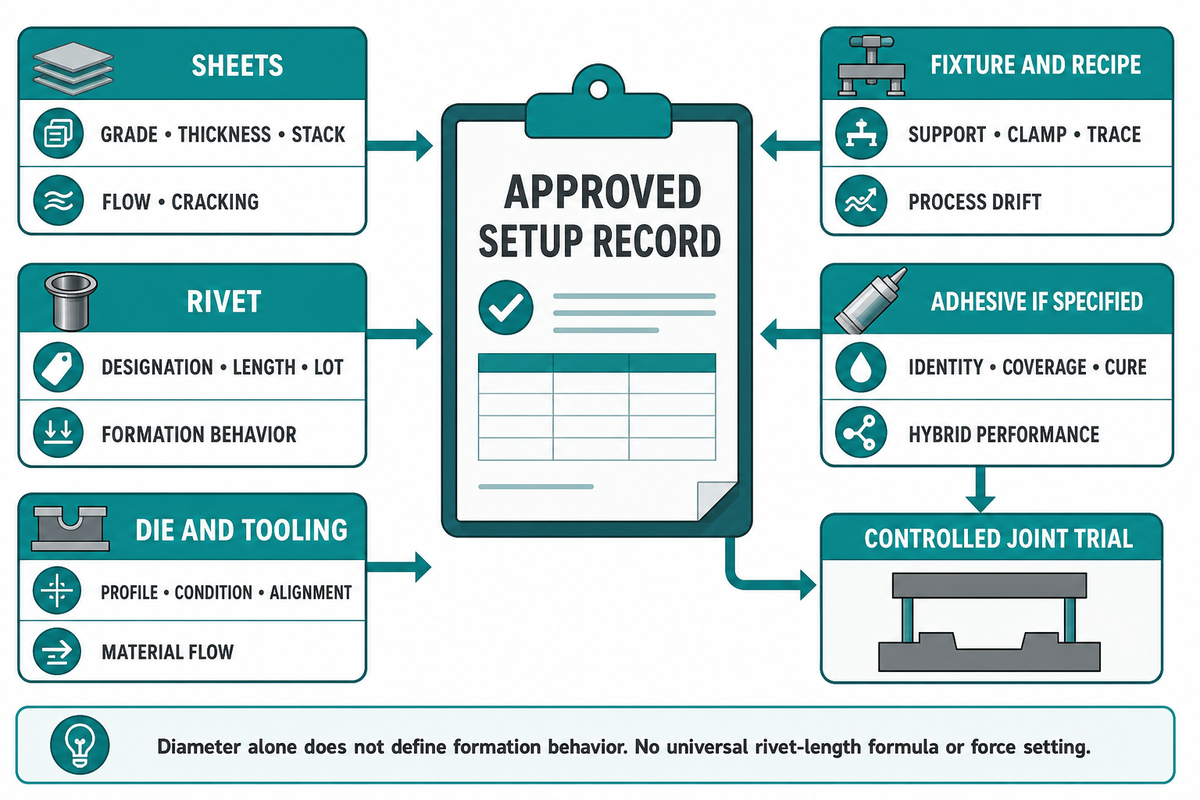
A drifting input can make a previously stable recipe invalid. Check the approved setup for actual sheet grade, temper, thickness, layer order, coating, surface condition, adhesive system, rivet designation, die designation, fixture support, and recipe revision against the actual. Purchase descriptions such as “aluminum sheet” or “same rivet diameter” are too broad for a defect analysis.
| Input | Evidence to compare | Why it matters |
|---|---|---|
| Sheets | Grade, temper, actual thickness, layer order, coating, and lot | Changes piercing, flow, support, and cracking behavior |
| Rivet | Full designation, length, hardness family, coating, and lot | Diameter alone does not define formation behavior |
| Die and tooling | Profile, depth, revision, condition, alignment, and maintenance record | Controls support and lower-sheet material flow |
| Fixture and recipe | Part support, clamp condition, endpoint, and trace reference | Separates process drift from input mismatch |
| Adhesive, if specified | Identity, storage and age, application, coverage, gap, and cure record | Hybrid-joint performance can depend strongly on the adhesive system |
A peer-reviewed study on defined EN AW-6016 lap joints showed that the adhesive layer in the riv-bonded specimens influenced both the static and fatigue behavior of the specimens. Representative rivet sections in that study had acceptable geometry. The reduced-bonding-area tests were performed on adhesive-bonded specimens. Therefore, they don’t provide evidence of inadequate adhesive coverage for a riv-bonded joint. The diagnostic lesson remains bounded: a hybrid joint needs adhesive and cure evidence as well as rivet and die records. Similar care is warranted when dissimilar materials alter the behaviour of the rivet during formation.
Don’t use a universal rivet-length formula or “add more force” as the first correction. Don’t infer aluminium rivets merely because the sheets are aluminium. Self-piercing riveting is a different method of joining from conventional riveting and resistance spot welding, so their repair rules and process settings can’t be interchanged. Simitch’s specific SPR equipment guidance also advises that more force isn’t always the right solution. An assessment of the actual stack and tooling should be performed rather than using a setting from a visually similar assembly.
Read the Section Without Turning a Study Into an Acceptance Limit
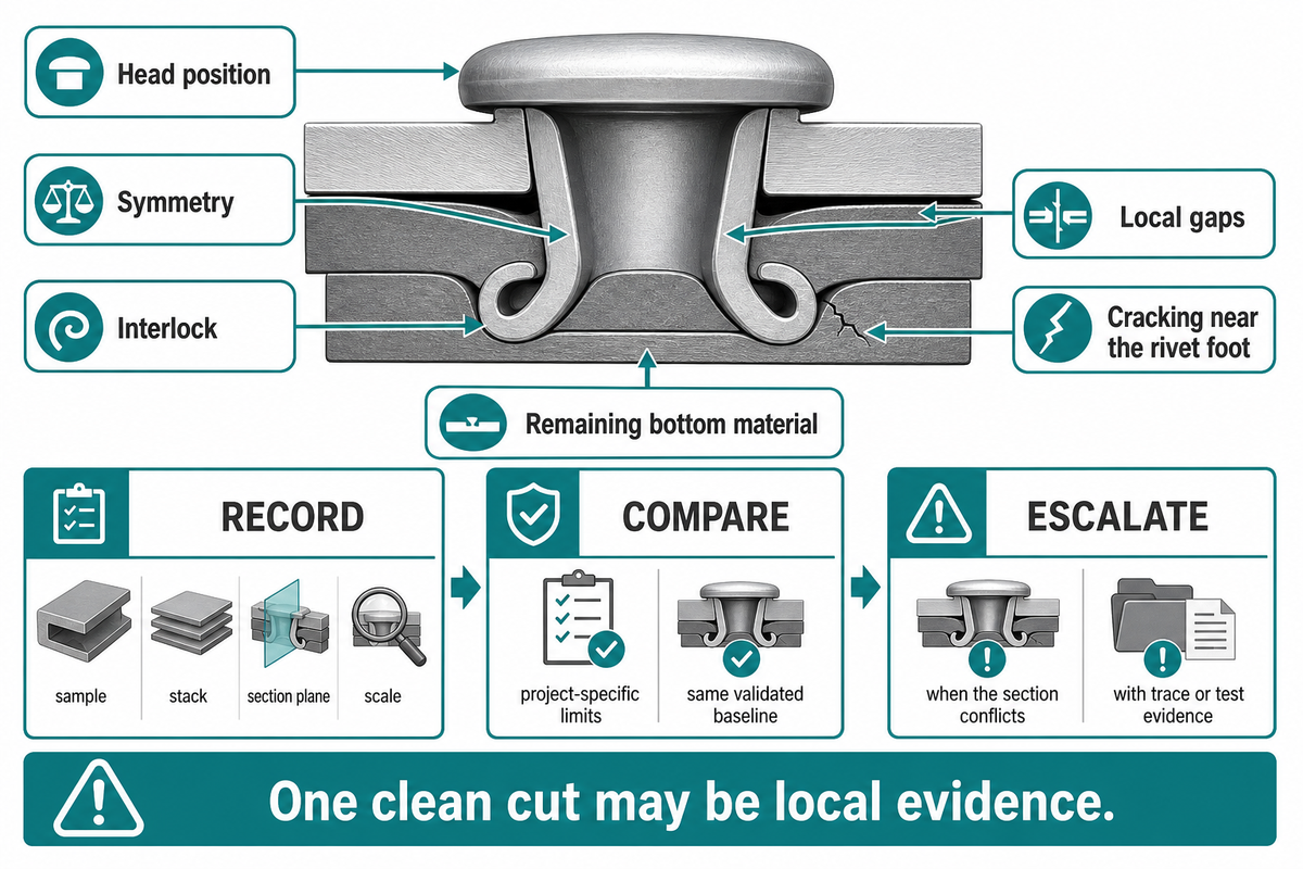
A section may show rivet-head position, symmetry, interlock, remaining bottom material, local gaps, and cracking near the rivet foot. The quality of self-piercing formation is thus assessed based on multiple features rather than one dimension. Include the sample identity, preparation method, section plane, magnification, measurement definitions, and project limits next to the image. Without those data, an impressive polished photo may look convincing, yet may not allow an audit.
The section plane matters. A 2021 computed-tomography study intentionally damaged SPR samples and took multiple radial sections. In its example of rivets, the defect was present in only a portion of the radial views. The authors noted that a conventional macro-section might miss that defect. This doesn’t establish a general miss rate or a required number of cuts. It shows that a single clean cut may be local evidence.
Record
Sample, stack, rivet, die, recipe, section plane, image scale, and measurement definition.
Compare
Project-specific limits and a validated baseline for the same joint configuration.
Escalate
Asymmetry, cracking, breakthrough, missing coverage, or conflict with trace and test evidence.
Published interlock values are especially vulnerable to misinterpretation. A primary study of a defined AA5754 H111 stack reported that in its dataset, conventional linear X and Y interlocks didn’t accurately predict peel strength, whereas a volume-based interlock performed better. This study doesn’t negate the measurement of sections. It limits the scope of the general claim: A familiar dimension may be important for formation control without being a universal strength predictor.
Compare Inspection Methods for SPR Joint Quality

There are many methods of inspection that assess different things. A top view or a die-side view can assess exterior conditions, and a section can assess local internal geometry. A mechanical test evaluates a specified specimen under a specified load. In most cases, the relevant question isn’t which method is the best, but which hypothesis can the next method be used to answer?
| Trace | Physical sample | Interpretation | Action |
|---|---|---|---|
| Within validated band | Meets project criteria | Evidence agrees for this sample and configuration | Continue defined sampling and trace retention |
| Within validated band | Damaged or outside criteria | Possible blind spot, wrong reference, wrong sample link, or condition outside the validated fault set | Contain; verify identity; challenge the monitoring plan |
| Outside band | Meets sampled physical criteria | Process changed, measurement drifted, or the sample missed the affected condition | Hold release until the deviation is explained |
| Outside band | Outside criteria | Agreement on abnormality, not yet on root cause | Use section, input, fixture, and maintenance evidence to isolate cause |
The Welding Institute describes force-displacement monitoring as comparison with a benchmark curve and an experimentally established tolerance band. It warns the correlation between monitor indications and joint properties may not be precise. A green curve therefore cannot overrule a cracked or penetrated sample. The related guide on force-displacement curve validation describes how a reference window is qualified.
Keep the reference trace, material revision, tool revision, recipe, and physical sample ID together. This arrangement prevents comparing a suspect joint to an incorrect baseline and accepting a monitoring package without evaluating the faults that are of concern in the actual stack.
Verify the Fix Before Releasing Recurring Faults
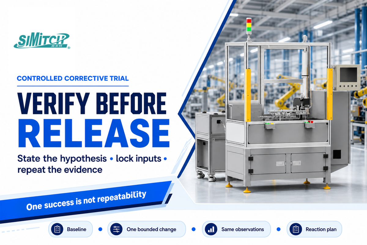
A corrective trial must be guided by a stated hypothesis. Preserve the baseline, change one bounded input where practical, and keep all other recorded conditions stable. Compare the same levels of observation before and after the condition is varied. If there’s a need to change a number of variables together, then treat the result as a new setup that needs qualification rather than proof of one root cause. The broader guide to planning an SPR joint trial covers feasibility and qualification inputs.
| Illustrative field | Baseline | Controlled trial | Release evidence |
|---|---|---|---|
| Hypothesis | Bottom-sheet crack linked to an input mismatch | Restore the approved input identity | Named owner accepts against project criteria |
| Locked inputs | Recorded stack, fixture, die, rivet, and recipe | Same except for the declared change | Revision-controlled trial sheet |
| Observations | Top, die-side, trace, section, and named test | Same observation set and definitions | Repeatability across relevant variation |
| Reaction plan | Contain on physical damage or trace deviation | Stop if a new defect appears | Documented limits, escalation, and sample retention |
A single successful demonstration doesn’t assure absence of a repeated fault. Challenge the revised configuration against the defined scope of variation of the material, tools, processes and environment. Review the first production evidence after release. If the defect returns, compare identities and wear state before increasing force or widening the monitoring band.
Use numerical analysis when the mechanism remains unclear
Finite element modeling and other numerical analyses can compare mechanisms such as local material flow, residual stress distribution, or sensitivity to geometry. The failure model, contact definition, material data, and boundary conditions, however, must be calibrated against physical specimens from the relevant configuration. Simulation can support a trial and minimize the number of blind changes. It can’t perform any self-validation nor replace mandatory joint tests.
Request a Traceable SPR Defect Trial From the Supplier

Send the supplier a defect handoff that describes the symptom and associates it to the actual assembly. Provide the stack drawing, material certificates or exact designations, layer order, coating and adhesive information, rivet and die information, defect and section images, trace files, fixturing information, rate and throughput data, and the project acceptance owner. Also ask the supplier what evidence they’ll return for each trial modification.
Defect-to-Trial Evidence Sheet
- Observed condition
- Bottom-sheet crack at the die-side button, tied to sample and lot
- Questions to isolate
- Material identity, stack order, adhesive state, rivet/die match, alignment, support, and recipe
- Supplier records
- Input list, revision-controlled settings, force-displacement trace, exterior images, documented section, and named test result
- Unknown branch
- If the original joint or trace is missing, root cause remains unresolved
- Release authority
- Customer design or quality owner named in the trial plan
To summarize, for a constrained equipment discussion, tie the required sample records to the operations actually provided. Simitch describes servo riveting assembly systems for SPR joining and system integration. Capability questions can be answered with the first-party documents. The first-party page does not independently prove defect-elimination rates, process universal windows, or customer acceptance for a particular customer stack.
Normalize defect-investigation scope before comparing price
Each supplier must price the same work. The American Society for Quality classifies quality costs as prevention, appraisal, internal and external failures. In the context of an SPR investigation, this analysis would determine which supplier performs sample preparation and inspection, sectioning, trace analysis, controlled experiments, reporting, retesting, scrap analysis, and handling of rejected products. This is a scope framework, not an SPR price model.
APQC’s public historical review identifies that organizations use different quality costs definitions and calculations. That supports a practical caution: two totals aren’t comparable until their components and calculation boundaries are equal. Don’t use the APQC participant counts as a current SPR benchmark. Request actual commercial figures from each supplier.
| Scope item | Included? | Required return | Buyer owner |
|---|---|---|---|
| Sample preparation and sectioning | Supplier states quantity and method | Traceable images and measurements | Quality engineering |
| Controlled equipment trial | Supplier states variables and repetitions | Revision-controlled trial report and traces | Process engineering |
| Retest and reject handling | Included or separately priced | Disposition, limitations, and follow-up terms | Procurement and quality |
Send Simitch the stack drawing, defect photos, linked trace, required throughput, and acceptance owner. Ask for a trial plan that preserves sample identity and returns section, signal, and revision evidence for the actual joint.
What Changing Materials Mean for Defect Monitoring
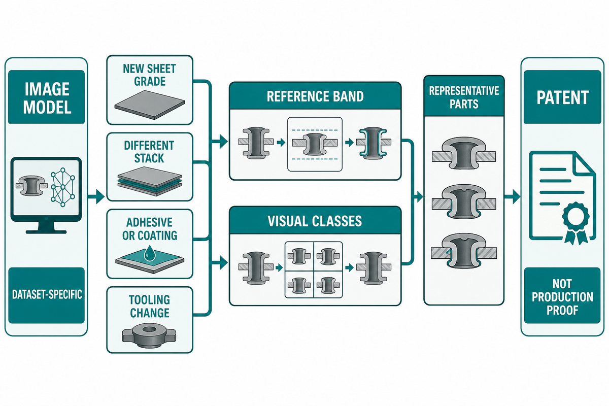
New sheet grades, different stack up materials, adhesives and coatings can change both joint design and the signal used to monitor it. In an aluminium car body, a change from one sheet family to another can shift the validated process response. Carbon fiber reinforced layers and other dissimilar stacks can add different forms of damage and raise support questions. It’s required to validate the reference band and visual classes with representative parts after a material or tooling change.
Peer-reviewed studies published in 2023 and 2024 describe image- and attention-based methods for SPR defect detection. One open study built its reported results from a constructed image dataset, including augmentation. These defect-detection methods can support quality control research for new joining techniques, but a monitoring model trained on one image set or stack should not be treated as validated for another. The studies do not establish universal production accuracy, internal-geometry coverage, or transfer to a purchased cell without representative validation.
Published patent applications also describe artificial-intelligence approaches to joint-quality prediction. While a patent records a proposed invention and ownership claim, it is not proof of deployment, certification, or production performance. Keep research direction separate from the acceptance evidence required for the customer’s materials and process.
Frequently Asked Questions
Which self-piercing riveting defects are common?
Commonly investigated conditions in a joint include raised or recessed rivet heads, inadequate flares or interlocks, bottom sheet breakthrough, button or sheet cracking and asymmetric formation. Rivet buckling and missing or double rivets are also conditions that can be investigated. The applicable drawing, joint specification, and design authority decide acceptance. A generic defect list doesn’t define allowable limits.
How are self-piercing riveting defects measured?
Use linked exterior observations, section measurements, process traces and required mechanical tests. Record the sample, stack, rivet, die, recipe, section plane, and measurement definition. Head position, interlock, remaining material and symmetry answer questions; named mechanical tests answer defined loading questions.
What self-piercing riveting defects are allowed?
Only the client specification, the authorized design or quality owner can define ‘allowed conditions’. Mechanisms and inspection methods are described in published studies, but their results and conclusions apply to the materials, geometries, tooling and loaded cases of the studies. An ‘auto pass’ signal for a machine can’t waive a crack or dimensional limitation in the approved conditions.
What are self-piercing rivets?
Self piercing rivets are semi-tubular fasteners that are driven through the upper sheets or plate into a supported lower sheet. The rivets pierce and flare in the stack to create interlock, typically without a preceding hole. Please refer to the broader self-piercing riveting process overview for general operating principles.
Can a defective SPR joint be repaired by riveting it again?
Don’t re-hit, add a rivet, enlarge a hole or substitute another joining method without an approved repair procedure. The defective joint must be retained, and the affected assembly must be identified first. Repair can alter load paths, edge distance, sheet damage, sealing and corrosion protection, and affect access for inspections. The Product Design Authority must define the repair method and evidence.
What does riveted joint mean?
A riveted joint uses one or more rivets to connect components mechanically. Conventional solid riveting, blind riveting, and self-piercing riveting form their joints differently. Their defect language and corrective actions can’t be exchanged without checking the process and product specification.
Why did defects return after a successful trial?
Compare the production material lot and thickness, coating or adhesive condition, rivet and die lots, tooling wear, alignment, fixture support, recipe revision, and monitor reference with the successful trial. The trial may also have missed normal variation. Use the retained baseline and reaction plan to identify which input changed before widening limits.
References and Sources
- A review of self-piercing riveting process, joint failure, and quality monitoring, Chinese Journal of Mechanical Engineering.
- Simple visual inspection of SPR joints, TWI.
- Detailed examination of an SPR joint, TWI.
- Monitoring the SPR process for quality assurance, TWI.
- ISO 12996:2013, Mechanical joining, destructive testing of joints, specimen dimensions and test procedure for tensile shear testing of single joints, ISO.
- Volumelock as a strength-prediction approach for a defined SPR dataset, open-access primary study.
- Automatic extraction of cross sections from CT data of mechanical joining elements, Discover Applied Sciences.
- Load-bearing capacities and fracture modes of SPR, adhesive-bonded, and riv-bonded aluminum joints.
- Cost of Quality, American Society for Quality.
- The Challenging Cost of Quality, APQC.
About Simitch: Established in 2006 in Taicang, Jiangsu, Simitch develops intelligent joining equipment and system-level solutions, including hydro-pneumatic boosters, precision servo pressing, clinching, riveting, SPAC, and SPR technologies. They serve the automotive components, energy storage batteries, solar PV, home appliances, and HVAC markets.