Get in touch with Suzhou Simitch Machinery Co., Ltd Company

Quick Specs
| Common processes | Self-piercing rivet (SPR), blind rivet, orbital rivet, lockbolt |
| Typical actuation | Manual, pneumatic, hydraulic, servo-electric |
| Example force envelope | 80 kN / 200 mm stroke / 0-333 mm/s (servo riveting class) |
| Applicable OSHA baseline | 29 CFR 1910.212 (general machine guarding) |
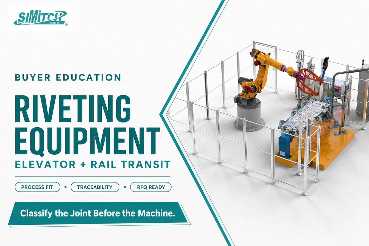
Riveting equipment for elevator & rail transit refers to a narrow set of joining processes — self-piercing, blind, orbital, and lockbolt riveting — matched to fastening tasks that welding or adhesives cannot always reach or that assembly teams do not want to reverse. This guide walks through what these machines actually do, where they show up on an elevator car or a railcar, how they compare with adjacent joining methods, and what the underlying standards and monitoring technology can and can’t promise a buyer.
For product-family context, see SIMITCH riveting equipment.
Key Takeaways
- A peer-reviewed 2023 study confirms that the standard force-displacement monitoring method used on self-piercing riveting can’t detect several real defect types, including rivet offset and sheet cracking.
- Riveting machines are explicitly excluded from OSHA’s mechanical power press standard (1910.217); general machine guarding under 1910.212 is the applicable federal baseline instead.
- Elevator and rail-transit fastening decisions hinge on structural classification, whether a joint is load-bearing, before any process or machine choice.
- Industrial riveting equipment is shifting toward servo-controlled machines that log force and displacement per cycle, corroborated by multiple independent equipment makers, not one vendor’s marketing claim.
What Counts as Riveting Equipment for Elevator and Rail Transit Manufacturing?
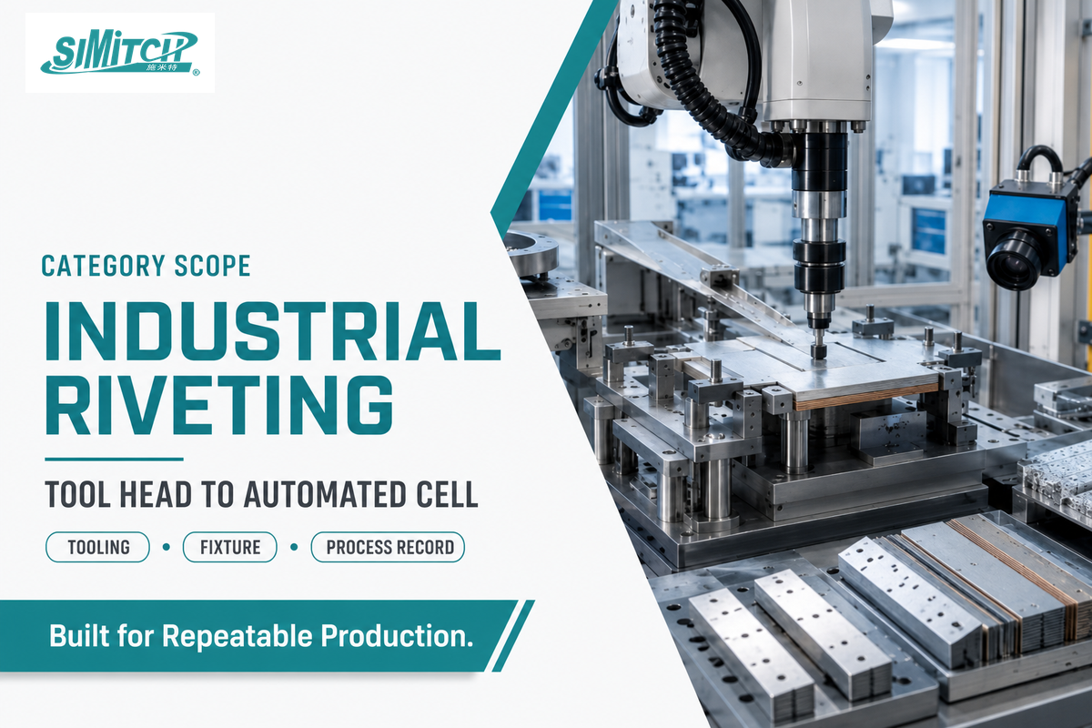
Riveting equipment for elevator & rail transit manufacturing is industrial machinery that sets mechanical fasteners, rivets, into sheet-metal plate, panels, or structural assemblies without heat or a threaded connection. That definition separates it immediately from a hand-held pop-rivet kit (the family of pop rivet tools most people already own): the equipment covered here ranges from bench-mounted presses to fully automated, part-program-controlled cells, sized for repeatable production rather than one-off repairs.
In practice, the rivet does the work a bolt or a weld bead would otherwise do. A driven or formed rivet mechanically locks two or more sheets together, and depending on the process, either deforms through a pre-drilled hole (blind riveting) or pierces and reshapes the material itself (self-piercing riveting). Industrial machines automate the drilling, feeding, and setting steps that a hand tool leaves to the operator across material stacks that must be qualified for the selected rivet family, tool head, and die.
Elevator manufacturing and rail-transit production share a common demand: high-mix assembly of sheet-metal panels, brackets, and structural members where access is often limited to one side, and where every fastened joint needs to be traceable back to a specific machine cycle. In markets where “lift” is the standard term for elevator, this equipment category is identical — only the terminology changes, not the machinery. From here, this guide works through the process types, the application context, and the standards that shape a buying decision, not a specific vendor’s configuration, which is covered on Simitch’s riveting equipment configuration page for elevator and rail transit.
Types of Riveting Processes and Machines
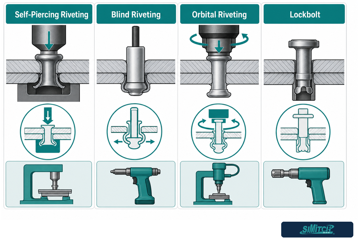
A riveting tool sets and forms a rivet in one motion, in contrast to a screw or bolted connection, which needs a matching thread cut into the material first; the goal in either case is to attach two or more sheets permanently. Riveting machines fall into four process families, self-piercing, blind, orbital, and lockbolt, each built around a different way of forming the rivet, and each with its own tooling and access requirements. Rivet diameter and grip length must match the specific material stack. Picking the wrong family for a given joint is a recurring source of downstream defects in the fault taxonomy published by Design World; the underlying rivet-setting mechanisms themselves are tested against ISO 12996‘s mechanical-joining test procedure.
Self-piercing riveting (SPR) — sometimes searched as a self piercing riveting machine or a general-purpose riveting press machine — drives a semi-tubular rivet through the top sheet and partially into the bottom sheet without a pre-drilled hole, forming an interlock rather than a clean punch-through. It needs a die on the far side of the joint, so both sides of the material stack must be reachable. Blind riveting installs a rivet from one accessible side through a pre-drilled hole: a mandrel is drawn through the rivet body, expands the far end, then snaps off — the process that makes it ideal when the back of the panel is closed off. Orbital riveting (an orbital riveting machine) uses a press head that hammers or rolls a rivet shaft down in a circular motion, suited to solid, tubular, and compression-tubular rivets on parts that can tolerate the radial forming load. Lockbolt systems pair a pin with a swaged collar for a high-clamping-force joint that resembles a rivet in installation but performs closer to a structural bolt.
Actuation is a separate choice layered on top of process type. A handheld rivet gun or a bench-mounted arbor press suits low volume and field repair. Pneumatic tools trade some precision for speed and lower cost while using the buyer’s available shop-air supply. Hydraulic systems package high force into a compact head. Servo-electric systems add programmable force and displacement control, at a cost premium that can make sense when a line runs multiple part variants.
⚠️ Common Failure Modes
Design World’s fault taxonomy for blind riveting names five recurring problems traced back to setup, not the rivet itself: a high mandrel break (grip thickness too thin, oversized hole), a pull-through (grip range above maximum, undersized nosepiece), a popped head, an incorrect rivet location from misaligned tooling, and a sheared secondary head from insufficient rivet length. In each case, the wrong nosepiece or improper tooling alignment shows up as the underlying cause more often than a defective fastener.
What are the four types of rivets?
The four riveting process families — self-piercing, blind, orbital, and lockbolt — correspond to four distinct rivet-setting mechanisms rather than four physical rivet shapes. Self-piercing rivets are semi-tubular and pierce their own hole; blind rivets rely on a mandrel that snaps off after expanding the rivet body; orbital-set rivets can be solid, tubular, semi-tubular, or compression-tubular depending on the joint; lockbolt fasteners pair a grooved pin with a swaged collar.
Buyers selecting equipment should confirm which rivet family a machine is built around before comparing force ratings, since a press sized for orbital forming will not set a self-piercing rivet without a different tool head and die.
Where Riveting Fits in Elevator Car Manufacturing
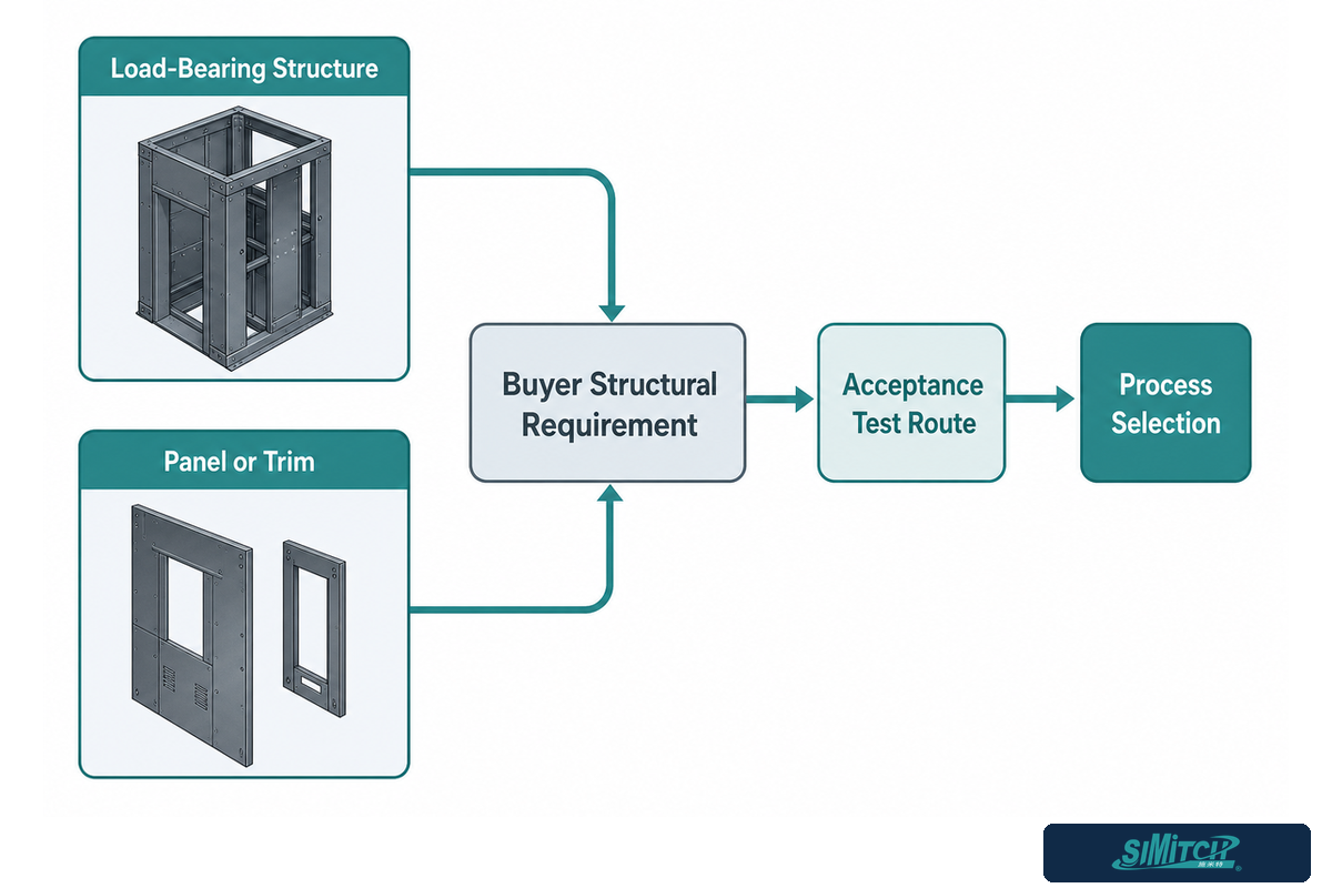
Elevator car manufacturing uses riveted joints on panels, door assemblies, and guide-rail-related brackets where the connection needs to hold its position through repeated door cycles and car travel without loosening. Car-bottom, frame, and cabin-panel structure generally carries some load; door components and trim more often do not, and that distinction should be settled before any fastening method is chosen.
What follows is general sheet-metal assembly engineering practice, not a verified elevator-industry standard or code: before specifying riveted joints on any elevator structural member, confirm which connections are classified as load-bearing under the applicable local elevator code and which are cosmetic or non-structural, then match the acceptance criteria — sample testing, sectioning, or non-destructive checks against a recognized procedure such as ISO 12996 — to that classification. Panel and door-frame fastening in general industrial assembly most often favors blind or self-piercing riveting for its one-pass installation and consistent finish; anything identified as load-bearing should be engineered and validated against the buyer’s own structural requirement, not assumed from a generic process description.
Where Riveting Fits in Rail Transit and Rolling Stock
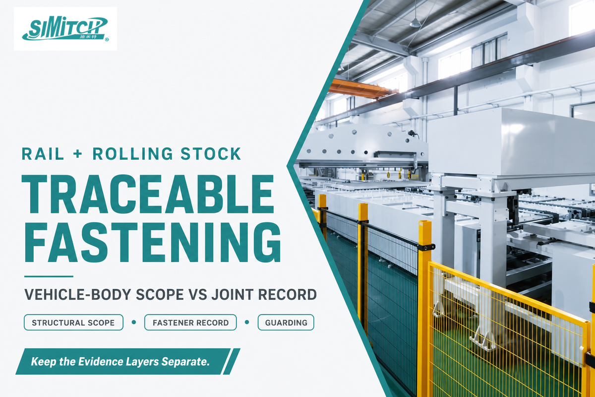
Rail-transit and rolling-stock assembly, spanning both railroad freight equipment and passenger train manufacturing, uses riveted and other mechanically fastened joints on side frames, bogie components, and lightweight roofing panels, alongside welded and bolted connections chosen for their own reasons on other parts of the car.
EN 12663-1:2010+A2:2023, the current railway-vehicle-body structural requirements standard, sets the minimum structural loads a locomotive or passenger-rolling-stock body must withstand — it governs vehicle-body-level structural validation, not the qualification of an individual riveted joint or the selection of riveting equipment itself.
Rail vehicle manufacturers treat fastener traceability as a compliance requirement, not an optional extra. Stadler Rail AG reports that thousands of threaded and nonthreaded fasteners are used to assemble a railcar.
“For reasons of product liability, our fastening processes require exact inspections and complete documentation. This ensures that every fastened joint is still traceable years later.”
That traceability requirement is a useful buyer checklist item in its own right: a riveting cell for rail-transit work should be able to record which fastener, which cycle, and which acceptance result belongs to which joint, years after the car has entered service, not simply confirm that a rivet was set.
Riveting vs Welding vs Clinching vs Threaded Fasteners, The Riveting Process Fit Ledger
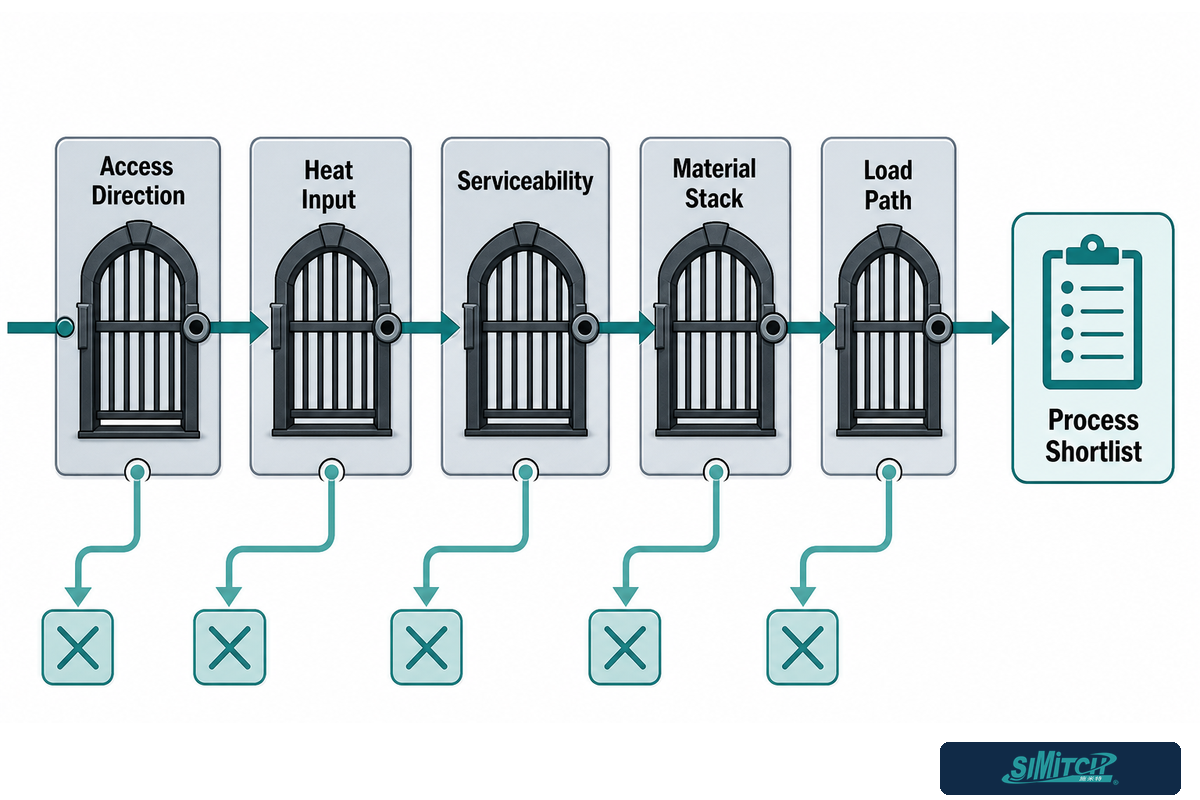
Riveting outperforms welding, clinching, and threaded fasteners on jobs that need one-sided access, no heat input, and a joint that’s easy to inspect after the fact, but each alternative wins on its own set of jobs, and no single joining method is correct across an entire elevator or railcar structure. That comparison lays out the tradeoffs by the dimensions that actually change a buying decision, not a generic quality ranking.
| Dimension | SPR Rivet | Blind Rivet | Orbital Rivet | Weld | Clinch | Threaded Fastener |
|---|---|---|---|---|---|---|
| Access needed | Both sides (die-side reaction) | One side only | Both sides | Both sides (electrode/torch) | Both sides (punch/die) | Depends on nut/insert type |
| Heat input | None | None | None | High — distortion risk | None | None |
| Reversible / serviceable | No (drill out) | No (drill out) | No (drill out) | No (cut/grind) | No (drill/pry) | Yes |
| Pre-drilled hole required | No | Yes | Usually yes | No | No | Yes |
| Dissimilar materials | Good (with validation) | Good | Good | Limited | Good | Good |
| Typical elevator/rail use | Panels, brackets | Closed-back panels, trim | Solid/tubular fastening points | Primary structural frames | Light-gauge assemblies | Removable panels, access covers |
| Equipment cost tier | Mid-high | Low-mid | Mid | Mid-high | Mid | Low |
| Governing standard family | Mechanical joining (ISO 12996) | Blind-rivet/lock-bolt (ISO 13469) | Mechanical joining (ISO 12996) | Welding procedure standards | Mechanical joining (ISO 12996) | Fastener/torque standards |
| Limitations / Not suitable for | One-sided-access-only joints | High shear-load structural joints | One-sided-access-only joints | Heat-sensitive coatings, thin sheet warping | High-strength steel above typical clinch capacity | Vibration-loosening without locking hardware |
Simitch manufactures self-piercing riveting, servo riveting, clinching (including roll clinchers for continuous seam work), SPAC self-clinch fastening, and hot-melt connection equipment within one product line. That range lets a buyer compare several joining routes against the same part, material stack, access direction, and load path instead of starting from one preselected process.
Industrial Riveting Machine Classes at a Glance
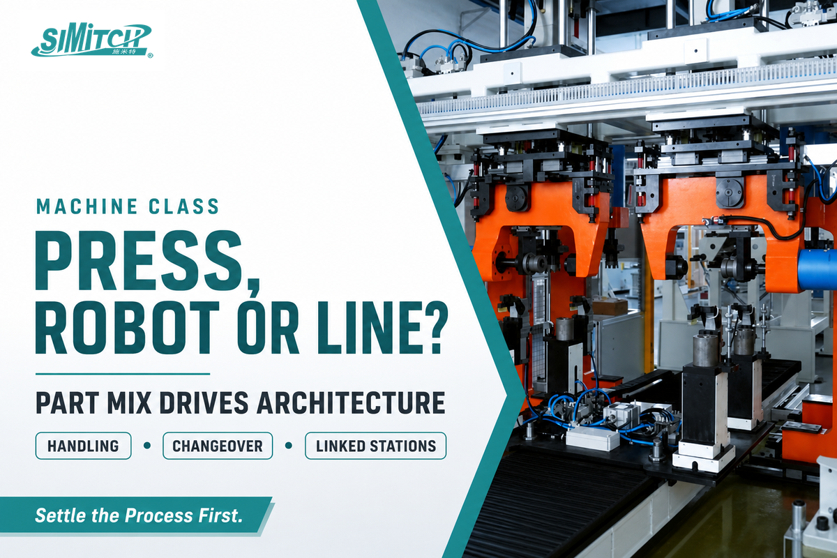
Industrial riveting machines fall into four broad classes, C-frame presses, portable/handheld tools, robotic cells, and integrated production lines, and the right class depends far more on part-mix and volume than on any single process choice covered above. A standalone press suits a stable, high-repeat part family; a robotic cell earns its cost when several part variants share a line. Whichever class a buyer chooses, the joint it produces still has to pass a recognized test procedure such as ISO 12996, so machine class is a production-economics decision layered on top of the process choice, not a substitute for it.
| Comparison Point | Portable / Handheld | C-frame / Bench Press | Robotic Cell | Integrated Line |
|---|---|---|---|---|
| Best fit | Field repair, low-volume, large or fixed parts | Stable, high-repeat part family | Several reachable part variants | Multiple linked process steps |
| Typical automation | Operator-driven; no automatic tool change | Semi-automatic to fully automatic single-station | Robot motion with automatic tool/die change | Line-level control, data collection, interlocks |
| Typical cost range | Low | Low-mid | Mid-high | High |
| Typical cycle time | Operator-paced | Part- and tooling-dependent | Program- and handling-dependent | Set by the slowest linked station |
| Operator skill required | Basic | Basic to intermediate | Intermediate, robot programming | Intermediate to advanced, line integration |
| Floor space footprint | Minimal | Small, fixed | Moderate, reach envelope | Largest, multi-station |
| Changeover between part variants | Not applicable, single-purpose | Minutes to hours, tooling swap | Minutes, program plus tool change | Longest, full line reconfiguration |
| Force range achievable | Lowest | Low-mid | Mid-high, servo class | Highest, multiple stations |
| Maintenance complexity | Low | Low-mid | Mid, robot plus tooling | Highest, multiple integrated systems |
An automatic rivet machine built into an integrated line adds that data-collection layer on top of the basic setting function. One published Simitch servo riveting assembly system is rated for roughly 80 kN of force across a 200 mm stroke, running 0-333 mm/s, with force repeatability around ±2% and displacement repeatability near 0.01 mm . Numbers in that range describe one model example, not an industry norm — force and stroke requirements should be sized to the specific joint and part geometry, not read off a spec sheet in isolation.
Robotic riveting cells add a layer most buyers underestimate: alignment. Before a rivet is set, the tool head must align perpendicular to the joint surface, with alignment pins or vision-guided orientation checks confirming the part is positioned precisely enough for the process to remain inside its programmed force window. Repeatability depends on slide travel, fixture stiffness, mounting rigidity, and ambient conditions; a force rating alone does not establish position accuracy. Robot brands such as Fanuc are commonly paired with a riveting or clinching end-effector to give a cell flexible reach across several part variants; large panels may need separate handling equipment, and any pre-existing bend or roller-formed edge should be checked against the tool’s clearance envelope before a program is written. None of this changes the process choice covered earlier in this guide. It changes how reliably that process repeats once a robot, rather than an operator, drives the tool head. Cycle time and fixture flatness should be proven on the buyer’s actual part during acceptance testing.
What Riveting Process Monitoring Can (and Cannot) Prove
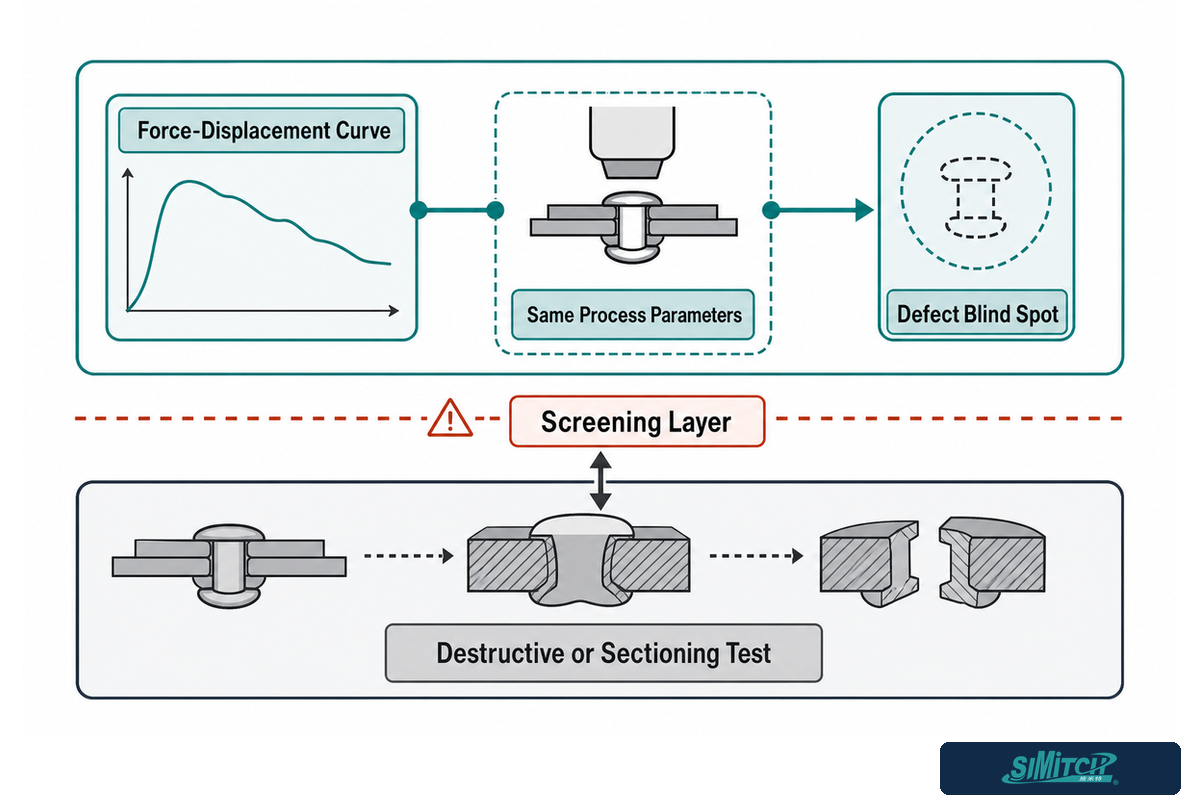
Force and displacement monitoring during riveting flags process deviations in real time, but it doesn’t by itself prove a joint meets its mechanical requirements — a peer-reviewed 2023 study found that the standard tolerance-band monitoring method used on self-piercing riveting is unable to detect several real defect types even when the recorded curve looks acceptable.
That study, published in Scientific Reports and indexed by the U.S. National Institutes of Health, describes a tolerance-band method that compares a joint’s force-displacement curve and offset against a preset acceptable band, then warns that it “is not only insensitive to lateral displacement but also unable to monitor defects such as rivet offset, sheet cracking, button cracking, button drop.” In plain terms: a curve that lands inside the tolerance band can still hide a joint that failed in one of those specific ways.
💡 Pro Tip
A related peer-reviewed paper on force-displacement monitoring adds a second limitation worth asking a vendor about directly: the curve is only valid for judging quality “within the same process parameters” — a monitoring setup calibrated for one rivet length and material hardness does not automatically transfer to a different combination.
None of this argues against monitoring — a modern servo riveting system that records force and displacement per cycle is still far more traceable than a machine with no feedback at all, and that data is exactly what supports the traceability commitment described in the rail-transit section above. Read honestly, monitoring is a screening layer, not a substitute for destructive or sectioning tests on a validated sample set when a joint is safety-relevant.
Standards That Govern Riveted Joints in These Applications
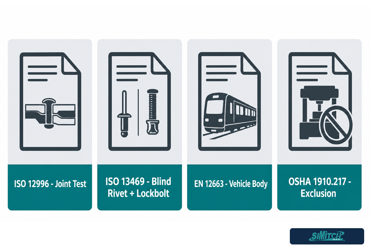
Riveted joints in elevator and rail-transit assemblies sit at the intersection of general mechanical-joining test standards, general machine-safety law, and vehicle- or building-level structural codes — no single standard covers “riveting equipment” as a category the way a pressure-vessel code covers boilers.
| Standard | What it actually covers | What it does not cover |
|---|---|---|
| ISO 12996:2013 | Specimen geometry and tensile-shear test procedure for single mechanical joints (generic “mechanical joining” scope) | Not a clinching- or riveting-specific certification; not a machine-selection standard |
| ISO 13469 | Testing procedures for interference-fit/form-fit blind-rivet joints and lock-bolt joints specifically | Does not cover self-piercing riveting — a different rivet process family |
| EN 12663-1:2010+A2:2023 | Minimum structural requirements for railway vehicle bodies (locomotives, passenger rolling stock) | Vehicle-body-level structural validation only — not a riveted-joint-process qualification standard; freight wagons fall under EN 12663-2 |
| 29 CFR 1910.217(a)(5) | Explicitly excludes riveting machines from OSHA’s mechanical power press standard | Not affirmative riveting-machine regulation — general 1910.212 point-of-operation guarding is the applicable federal baseline instead |
That last row surprises most buyers who assume an OSHA citation naming “riveting machines” must be a dedicated safety rule for them. It’s the opposite: 1910.217(a)(5) lists riveting machines among the equipment explicitly carved out of the mechanical-power-press standard, alongside press brakes and forging hammers. Safeguarding obligations for a riveting cell instead fall under the general point-of-operation guarding requirement at 1910.212, which applies to industrial machinery broadly rather than naming any single process.
From Guide to RFQ, The 3-Signal Procurement Trigger
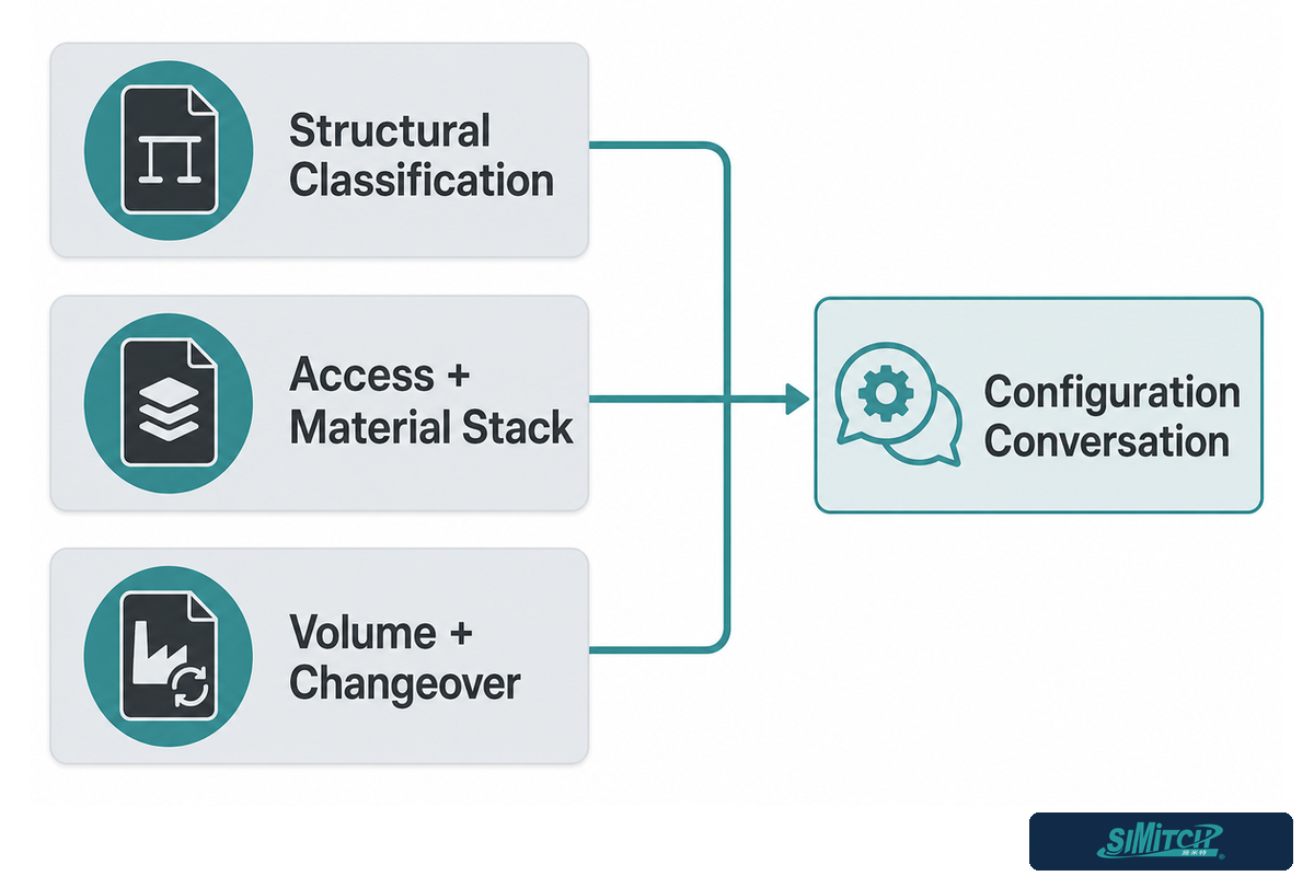
Three signals indicate a buyer is ready to move from research into a vendor RFQ: a confirmed structural classification for the joint, a known access direction and material stack, and a settled production-volume and changeover pattern. Without those three answered, even a detailed equipment quote is guesswork on both sides.
| Signal | What “ready” looks like | If not ready |
|---|---|---|
| 1. Structural classification | Buyer’s engineering team has confirmed load-bearing vs. non-structural status and the applicable acceptance route | Resolve internally or with a structural engineer first — a vendor cannot classify the joint for you |
| 2. Access & material stack | Drawings show one- or two-sided access, material types, thicknesses, and coatings at the joint | Request a sample part or drawing review before quoting a process |
| 3. Volume & changeover | Expected production rate and number of part variants per line are known | A rough range is enough to start — exact numbers can follow in the RFQ itself |
Once those three signals are answered, the next step is a configuration conversation, not another article. A configured cell usually carries a longer engineering and commissioning path than a standalone tool, so starting that conversation before the project schedule is fixed reduces avoidable redesign. Simitch’s riveting equipment configuration matrix for elevator and rail transit walks through dedicated-station, robotic-cell, and integrated-line options against exactly these inputs, and Simitch’s broader engineering services team can help scope an integration beyond the equipment itself. Start a Configuration Review →
Industry Outlook, Automation and Real-Time Monitoring
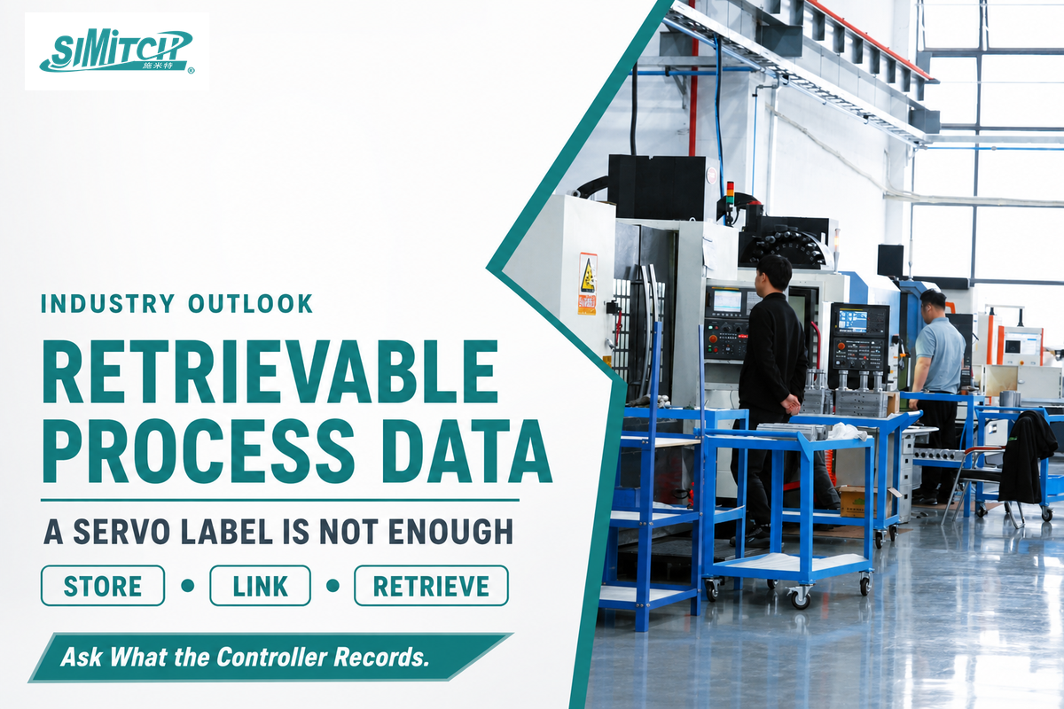
Riveting equipment is shifting toward servo-controlled machines that log force and displacement on every cycle, and that shift is changing what buyers should expect from new equipment, not because one manufacturer says so, but because multiple independent riveting-equipment makers have converged on the same direction. (Updated August 2026)
Current servo-product literature increasingly promotes per-cycle stroke and force monitoring, but the useful distinction is not the servo label itself. It is whether the controller stores a retrievable record, ties that record to the part and fastener, and exposes the data in a format the buyer can retain through the vehicle’s service life. That is the same traceability priority named by Stadler Rail AG’s bogie-assembly team.
Published estimates span roughly $300 million at the narrow end to multi-billion-dollar categories because some reports count hand tools while others include dedicated machines or combined drilling and riveting systems . Fortune Business Insights, for example, reports the broad automated drilling and riveting systems category at $5.02 billion in 2025 and $9.02 billion by 2034. The low-end range is not source-locked in this run, and the Fortune figures are a single-source forecast for a category much broader than the elevator and rail-transit equipment focus here; treat the entire paragraph as directional background, not as a plant-sizing input. The buyer’s real planning inputs are part mix, access direction, joint classification, target production rate, changeover frequency, and the evidence required at acceptance.
For a buyer evaluating equipment now, the practical takeaway is to ask what a machine actually records per cycle, not just whether it has a “servo” label — the same monitoring-limitation research covered earlier shows why a display-only readout is not the same as a retrievable record. Force and displacement data that lives only on a screen during the cycle offers little of the traceability value described earlier in this guide; data that is stored, timestamped, and retrievable years later is the difference that matters for both elevator and rail-transit acceptance requirements.
Frequently Asked Questions
Q: What is the recommended minimum spacing between rivets?
Minimum rivet spacing depends on rivet diameter, material thickness, and the applicable joint design standard rather than one fixed number that applies across every application or industry.
Industrial fastener guides often express spacing and edge distance as multiples of rivet diameter, but a generic multiplier is not a release criterion. The governing joint design standard, the buyer’s engineering drawing, and the specific material stack take precedence. Treat any published multiplier as a screening aid only, then record the chosen pitch and edge distance on the drawing and validate representative coupons or assemblies under the actual load direction before production approval. Changing rivet diameter, sheet thickness, die geometry, or material grade should reopen the spacing check. For self-piercing riveting, use the rivet-and-die maker’s joint-strength testing because pierce geometry changes how adjacent joints interact under load.
Q: What types of rivets are commonly used in aircraft?
Aircraft assembly is not this guide’s focus, but it is a common cross-reference: solid rivets remain the dominant fastener on airframe skins, installed with automated gantry and C-frame riveting equipment.
Aerospace riveting equipment makers such as an Electroimpact riveter or a Drivematic machine build automatic gantry, C-frame, and D-frame riveters for wing-panel and fuselage assembly, most often installing solid rivets, hi-loks, and lockbolts with automatic tool change between drill chucks, anvils, and injectors. Its engineering drivers — weight, fatigue life, and access from a moving gantry — differ meaningfully from elevator or rail-transit sheet-metal work, so aerospace equipment specifications should not be applied directly to a non-aerospace riveting decision.
Q: Does riveting equipment require different tooling for elevator car panels versus railcar structural members?
Yes, tooling selection follows the specific joint’s access direction, material stack, and structural classification, and those three inputs usually differ between elevator car panels and railcar structural members.
Elevator car panels and door assemblies are frequently thinner-gauge sheet metal with one-sided access constraints, favoring blind or self-piercing riveting with lighter force requirements. Railcar structural members, side frames and bogie components in particular, carry higher structural loads and may combine riveting with welding or bolted connections on the same assembly, which usually calls for higher-force equipment and more rigorous joint traceability records. Confirming both parts’ drawings before tooling selection avoids a mismatch discovered only after equipment purchase.
Q: How is a riveted joint inspected after installation?
Inspection generally combines in-process force and displacement monitoring with periodic destructive or sectioning tests carried out on a defined sample basis, since monitoring alone cannot confirm every possible defect type.
A first-off part should be checked physically before production starts, after which in-process monitoring can flag cycle-to-cycle deviations. Because monitoring cannot detect every defect mode, the control plan should define when destructive or sectioning tests are required and how the sampling frequency changes with joint criticality, process stability, material changes, tooling changes, and the buyer’s acceptance criteria.
Q: Can automated riveting equipment be retrofitted into an existing production line?
Yes, retrofitting is possible when the existing line already has a workable part reference, access path, safety boundary, and control interface in place before the new equipment arrives.
Retrofitting a robotic or automated riveting cell into an existing line generally requires confirming the current layout, sequence, and control interface before a vendor can commit to an integration method.
Q: What’s the difference between this guide and Simitch’s riveting equipment page?
The article explains riveting processes, applications, and standards in general terms; the separate Simitch equipment page walks a specific buyer through configuring an actual machine for their exact part.
Think of this article as the research step and the Simitch riveting equipment page as the configuration step. This guide does not recommend a specific machine, station type, or vendor; it explains the process landscape so that the configuration conversation, when a buyer is ready for it, starts from informed questions rather than a blank page.
About This Analysis
This guide draws on OSHA and ISO standards text, a peer-reviewed 2023 study on self-piercing riveting quality monitoring, and trade-press reporting on rail-transit fastening practice, cross-checked against Simitch’s own published equipment specifications where a first-party data point is used. Standards references reflect the versions confirmed at the time of research (August 2026); buyers should verify current editions before citing them in a specification.
Simitch has manufactured intelligent joining equipment since its founding in September 2006 in Taicang, Jiangsu, a region known as a hub for German industrial enterprises.
References & Sources
- 29 CFR 1910.217, Mechanical Power Presses — U.S. Occupational Safety and Health Administration
- Non-destructive monitoring of forming quality of self-piercing riveted joints — Scientific Reports, 2023, U.S. National Institutes of Health (PMC)
- ISO 12996:2013, Mechanical joining — International Organization for Standardization
- ISO 13469, Form-fit blind rivets and (lock) bolt joints — International Organization for Standardization
- BS EN 12663-1:2010+A2:2023, Structural requirements of railway vehicle bodies — BSI Standards Publication (distributed via ANSI webstore)
- Railcar Manufacturer Masters High-Mix Production — ASSEMBLY Magazine
Related Articles
- Self-Piercing Riveting (SPR) Machines — Simitch’s SPR equipment line, including access and die-side requirements
- Servo Riveting Assembly Systems — force/displacement-monitored servo riveting equipment specifications
- Clinching Machines & Equipment — rivetless sheet-metal joining as a comparison point to riveting
- Riveting Equipment for Elevator & Rail Transit (Configuration Matrix) — Simitch’s vendor-configuration tool for this exact application
![Hot-Melt Connection Molds & Equipment Guide [2026]](https://simitch.com/wp-content/uploads/2026/09/hot-melt-connection-molds-equipment-guide-featured-768x512.png)