Get in touch with Suzhou Simitch Machinery Co., Ltd Company

What Is Spot Welding and When Should You Use It?


Spot welding is a resistance welding process that joins overlapping metal sheets using electrode force and heat from an electric current. A melting weld nugget connects the sheets and electrodes hold the pressure as it cools.
Standard resistance spot welding fits on lapped joints that have access to the localized area and clearance for electrodes at both locations. That configuration may or may not work depending upon the part’s material grade, surface coating, and loads. Once a viable joint is determined, compare equipment scope and the price per good assembly.
By XCX
Resistance spot welding: definition and joint formation
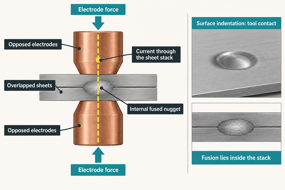
Resistance spot welding welds an internal joint into a stack of overlapped sheets. Electrodes draw current and apply pressure at the available weld spot. Electrical resistance heats a short segment of this current path causing it to melt a small volume of material.
The surrounding sheet remains largely intact, while the cooled nugget transmits force between the joined sheets.
The fundamentals of spot welding are easier to picture as a clamped electrical circuit. Current flows in through the electrode, passes through the contacting sheets, and out through the opposite electrode. TWI’s process guide describes how and why copper alloy electrodes transmit the current so well while focusing the majority of the heat into the work pieces.
Conventional spot welding generally uses neither filler wire nor shielding gas. The electrodes will still degrade and the coolant will still be used. Spot welding is a type of fusion joining, where a visible indentation marks tool contact while the fused connection lies within the stack.
Spot welding process: squeeze, weld, hold, release
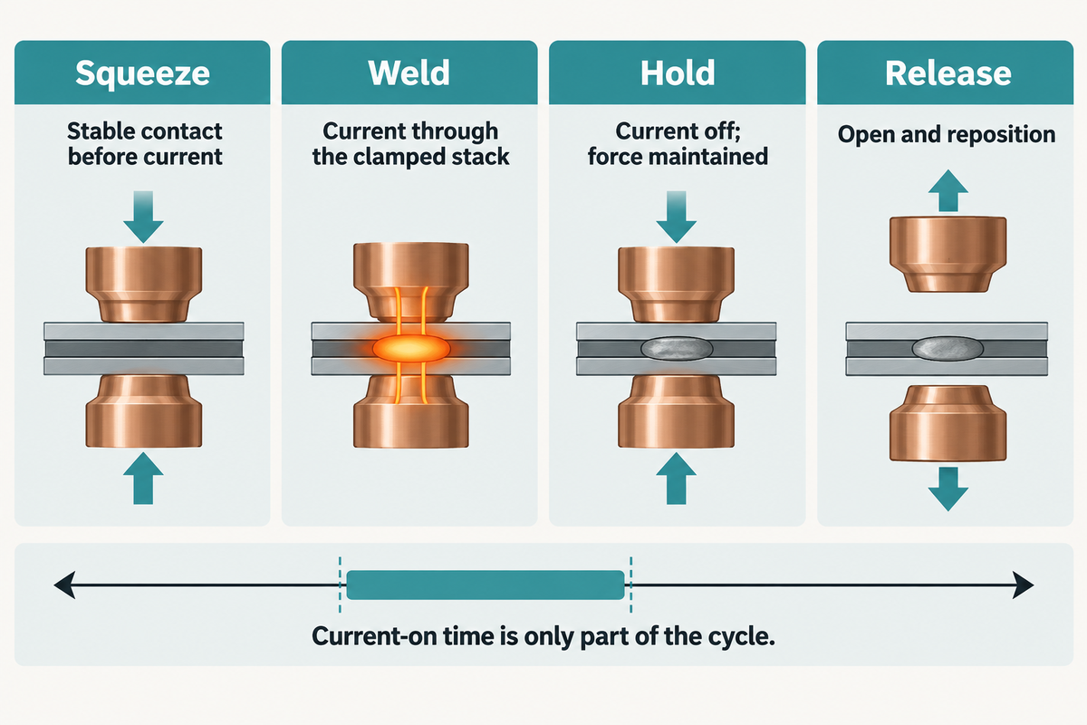
The spot welding process clamps the sheets, applies current, holds force after current is stopped, then releases the part. This time establishes contact, creates the nugget, and supports solidification. Current on time is only part of the cycle; electrode movement, part placement and handling also use production time at that station.
How does a spot welder work?
A spot welder directs the regulated current through the sheets between electrodes. Resistance converts electrical energy into welding heat at the joint. When the desired duration of the heat application expires, the current stops and electrode force persists.
After the molten region solidifies, the electrodes separate and the workpiece advances to the next position.
- Squeeze: bring the electrodes together and establish stable contact before current flows.
- Weld: deliver the specified current schedule through the clamped stack.
- Hold: stop current while maintaining force as the joint solidifies.
- Release: open the electrodes and reposition the assembly.
The current-on time in Pittner and Rethmeier’s 2022 case study (0.26 seconds) was compared with the gun process time (1.5 seconds). Their cap-profile configuration required 21.9 seconds per robot for ten spots plus movement. The measured boundaries explain how a short pulse can coexist with a longer assembly cycle.
Spot welding materials: steel, aluminum, copper and mixed stacks
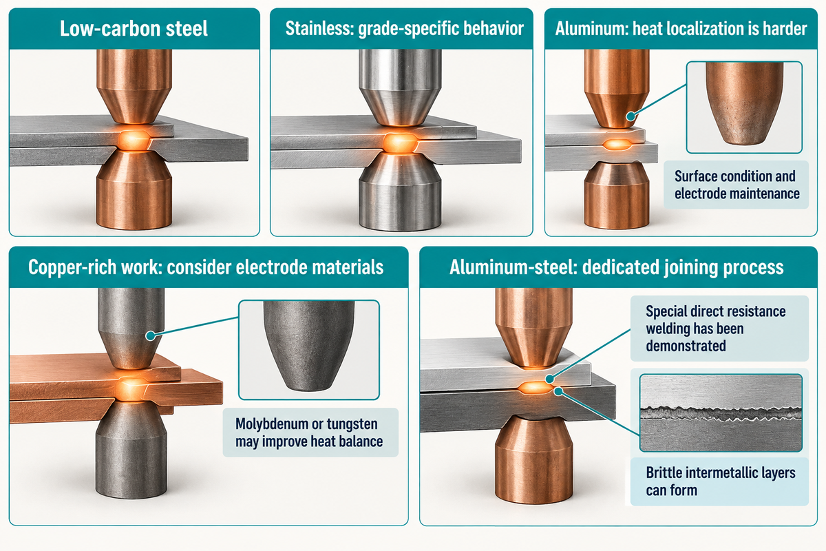
Low-carbon steel is a familiar candidate for resistance spot welding, while stainless steel, aluminum and copper require material-specific decisions. Conductivity, coating and electrode compatibility will all alter thermal interactions. A combined stack of aluminum and steel will pose additional metallurgical challenges, different to either material on their own, and this demands a dedicated joining process.
Coated sheet introduces an additional interaction at the electrode face. Zinc pickup can change the contact surface, making dressing and replacement part of process control. Stainless steel grades have varying thermal and electrical behaviour; the type number doesn’t give the particular schedule.
Can you spot weld aluminum?
Yes, aluminum can be resistance spot welded with the right equipment, electrodes and process control. The low electrical resistance and high thermal conductivity of aluminum make heat localization more challenging than with steel. Surface oxide and high electrode wear also influence repeatability, which makes surface condition and electrode maintenance critical to an aluminum process.
TWI’s aluminum guidance gives a commercial-quality example for 1.2 mm mill-finished sheets: 22–28 kA, 3–5 kN and 40–100 ms. These example conditions apply to that surface and sheet specification. Special direct resistance spot welding of aluminum to steel has also been demonstrated. AHSS Insights’ technical review describes zinc-coated H220 steel joined to aluminum alloy 6008-T66, with liquid aluminum wetting solid steel. The interface can form brittle intermetallic layers; electrode geometry changes that interface and the resulting joint.
For spot welding copper, electrode materials such as molybdenum or tungsten can provide a more suitable heat balance than conventional copper alloy tips. Separately, the public procedure scope of ISO 14373:2024 covers two or three low-carbon-steel sheets with a maximum single-sheet thickness of 0.4–3.0 mm. For unequal thicknesses, the sheet-thickness ratio must not exceed 3:1.
Spot weld access: advantages and disadvantages of the joint layout
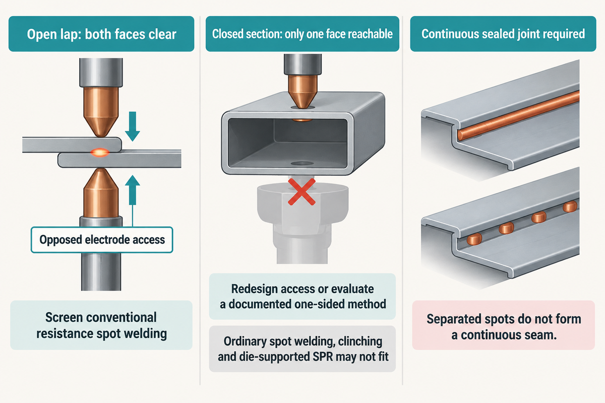
Opposite electrode access enables a conventional spot-welded joint. Both tips need to be able to access the same place and pinch the overlap without hitting flanges, fixturing, or other features. The advantages of spot welding feature localized joining and automation options; electrode clearances and opposite electrode impressions are practical disadvantages of spot welding for enclosed or cosmetic components.
This Access-and-Material Joining Route Table below blends material behavior with tooling geometry. Select the row matching your drawing as the initial selection; for a blocked tool path, the route changes before production rate becomes relevant. The geometry questions are developed further in our sheet metal joint design guide.
| Input condition | Initial route | Exclusion or next route |
|---|---|---|
| Low-carbon steel lap; both faces clear; shear-dominated load | Screen conventional resistance spot welding | Peel or fatigue duty adds separate joint tests. |
| Stainless lap; both faces clear; corrosion-sensitive service | Grade-specific resistance welding | Surface and corrosion performance remain part of acceptance. |
| Zinc-coated steel; both faces clear | Coating-specific schedule and tip care | AHSS crack sensitivity needs material-specific treatment. |
| Aluminum-only lap; both faces clear | Aluminum resistance-welding trial | Steel schedules and electrode life do not transfer directly. |
| Aluminum–steel lap; both faces clear | Compare validated thermal and mechanical routes | Interface metallurgy can control the thermal joint. |
| Copper-rich thin connection; both faces clear | Precision resistance-welding route | Conventional copper alloy tips may give unsuitable heat balance. |
| Closed section; only one face reachable | Redesign access or evaluate a documented one-sided method | Ordinary spot welding, clinching and die-supported SPR cannot be assumed to fit. |
| Heat-sensitive coating; punch and die accessible | Compare suitable mechanical joining | Material ductility, tool marks and service loads govern suitability. |
| Continuous sealed joint required | Evaluate seam joining or an appropriate sealing system | Separated weld spots do not form a continuous seam. |
| Threaded attachment required; prepared hole accessible | Evaluate a self-clinching nut or stud | This fastener route differs from rivetless sheet clinching. |
Welding parameters: current, weld time, force and electrode condition
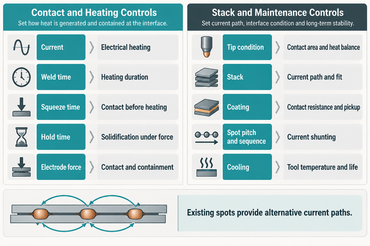
Welding current, weld time, electrode force & contact condition cooperate to form nuggets. More heat input can move a weak weld toward fusion, but excessive input can cause expulsion. Electrode shape, sheet fit and cooling broaden or narrow that window, so a current setting depends on the entire stack and welding schedule.
The simplified relationship Q = I²Rt describes heat energy: current squared times resistance times time. It doesn’t calculate temperature or qualify a production recipe. Contact resistance varies during heating and deformation, while heat also flows into sheets and electrodes.
Contact stability helps spot welding work reliably as the current traverses the sheet stack.
| Variable | What it changes | Useful record |
|---|---|---|
| Current | Electrical heating | Measured waveform and schedule |
| Weld time | Heating duration | Pulse sequence |
| Squeeze time | Contact before heating | Force establishment |
| Hold time | Solidification under force | Current-off-to-release interval |
| Electrode force | Contact and containment | Force at the tips |
| Tip condition | Contact area and heat balance | Geometry and dressing history |
| Stack | Current path and fit | Grade, gauge and layer order |
| Coating | Contact resistance and pickup | Surface specification |
| Spot pitch and sequence | Current shunting | Complete assembly layout |
| Cooling | Tool temperature and life | Flow and temperature records |
Previously formed spots provide alternative current paths during later welds. This shunting changes the heat available at the new joint. An original experimental study on shunting found strong effects from weld spacing and surface condition. Its authors also reported darker, larger impressions on some smaller shunted welds. A single isolated coupon therefore represents a different electrical layout from a multi-spot assembly.
Weld quality: defects, peel tests and joint strength
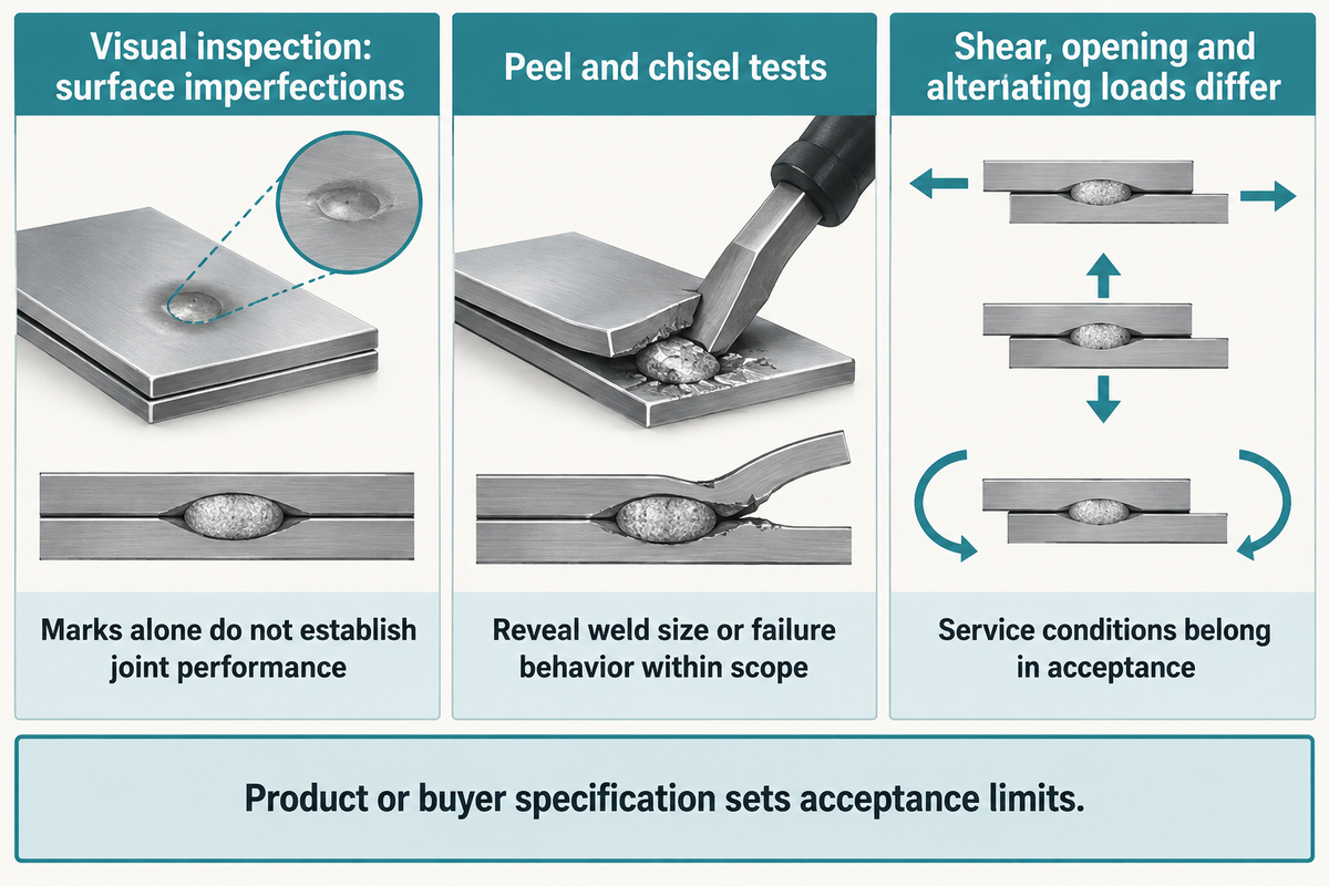
Assessing weld quality requires evidence of fusion and load capacity, along with an acceptable surface condition. Visual inspection can uncover surface imperfections and destructive inspection including mechanical testing can explore internal fusion and load performance. Electrode marks alone aren’t sufficient for determining nugget size, fatigue resistance or corrosion performance, especially when coatings or high-strength steels introduce additional failure mechanisms.
How strong is a spot weld?
A spot weld has a joint-specific load capacity depending on weld geometry, the direction of loading and its material configuration. The joint may be loaded in different directions or loading modes, as in tensile-shear, cross-tension and peel tests. A strong weld that’s loaded in shear may not hold up as well when pulled, alternately loaded or exposed to corrosion.
ISO 10447:2022’s public catalogue description identifies peel and chisel testing procedures and tooling. These tests reveal weld size or failure behavior within their stated scope. Acceptance limits come from the applicable product or buyer specification, rather than a universal hand-pull rule.
Expulsion indicates molten metal has escaped; sticking suggests an electrode/workpiece contact problem. Deep indentation and small nuggets can arise from different combinations of force, heating and tip condition. On zinc-coated advanced-high-strength steel, liquid metal embrittlement can introduce cracking near the weld. University of Waterloo research examines that material-specific mechanism; it shouldn’t be generalized to every steel grade.
From a quality assurance personnel perspective, the relevant distinction is between witnessing the change in the process and evidence of the joint performing to specification. Section testing, mechanical testing and manufacturing monitoring each provide different insights to the acceptance plan.
Spot welding applications: automotive panels, appliances and precision parts
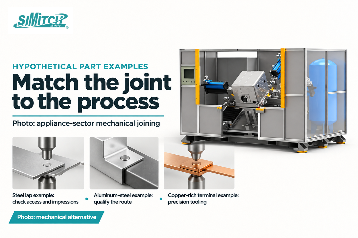
Spot welding is widely used for automotive sheet assemblies and also for appliances, steel furnishings as well as electronic devices, as shown in TWI’s application guide. Workload is different for these applications. A robot-mounted welding gun must accommodate panel access and movement, while a precision system controls timing, contact and energy for tiny, sensitive connections.
Consider, for example, a hypothetical low-carbon-steel appliance enclosure with easy-to-reach lap flanges. Here, a panel station can be evaluated for fixture clearance, visible impressions and the enclosure’s load requirements.
An assumed aluminum bracket attached to steel tips the balance. The coexistence of the metals may point toward a particular qualified thermal joining process or a mechanically appropriate solution. An assumed small copper-rich terminal points the eye toward precision tooling and electrode choice.
Resistance welding used for these types of fine joints requires a different equipment conversation than body-panel production.
Spot welding is also used in thin-part electronics manufacturing. Battery connections introduce additional cell and assembly hazards; a general spot welding application guide does not supply cell-welding settings.
Spot welding vs MIG, clinching and self-piercing riveting
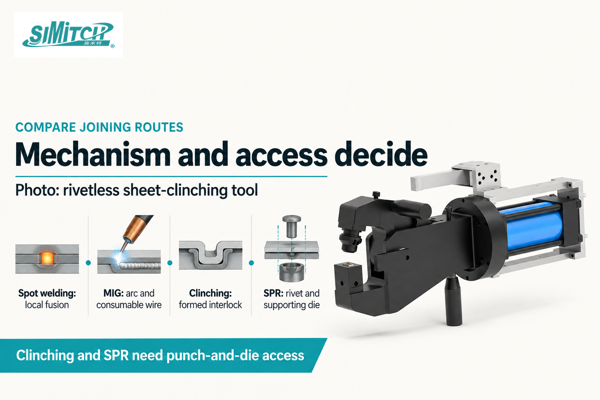
Spot welding accommodates local lap joints, and MIG accommodates arc-welded joint arrangements; mechanical techniques create an interlock or place a fastener. Heat-sensitive finishes favor cold joining; continuous seams and threaded attachments call for different kinds of joints. Inaccessibility could eliminate a proposed tool, despite the fact that its joining mechanism is suitable for the material.
“It is difficult to generalise the comparison of processes”
Is spot welding stronger than MIG welding?
Neither process is always stronger: spot welding joins discrete areas within a lap, whereas MIG welding can form a continuous bead in an appropriate joint. Their relative load capacity depends on the intended material, geometry and direction of load. Adjusting flange width, weld length or spot pattern affects the comparison too.
MIG welding employs arc welding in combination with a consumable wire. TIG welding employs a tungsten arc. These traditional welding methods are distinct from resistance heating.
Resistance seam welding forms a seam through successive overlapping welds, whereas laser spot welding employs a concentrated beam for its heat source.
The clinching process forms an interlock by locally deforming sheets without a separate rivet. SPR drives a rivet into the stack against a supporting die. Self-clinching nuts and studs, such as threaded fastener systems, are installed into suitable prepared holes; they’re a separate process family.
Clinching is a candidate, where ductile sheets can be formed to provide the interlock and where removing a dedicated fastener is advantageous. SPR adds rivet supply and feeding, but provides a different joint structure for use when peel or fatigue performance is the decision-maker. TWI’s sheet-joining comparison highlights these trade-offs; real-world load tests define the decision for the assembly.
Standard clinching and SPR do require good punch-and-die access. They can’t automatically solve the joining problem for a closed section accessible from one side only. Where the geometry and materials are suitable for mechanical fastening, SIMITCH clinching machines and self-piercing riveting machines provide solutions to those routes.
Read about rivet types to understand related fastener differences.
Spot welding equipment: machine scope, utilities and supplier questions
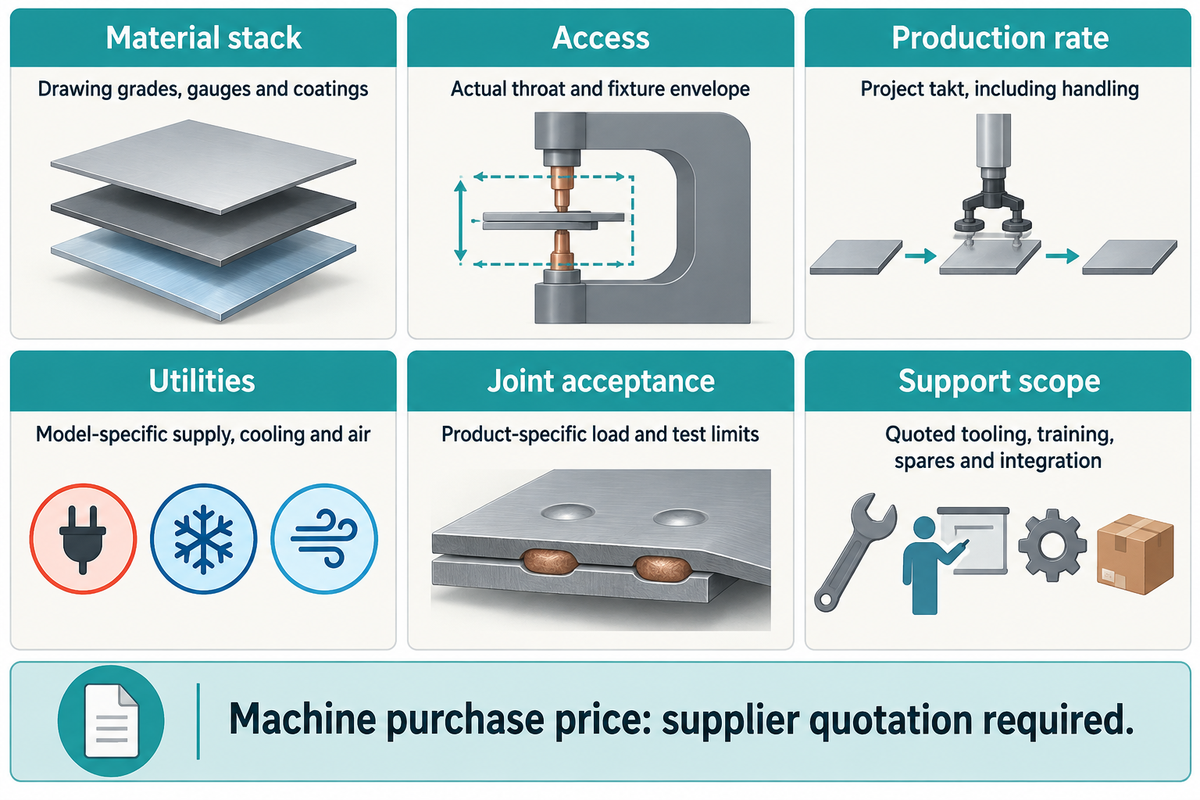
A spot welding machine quote needs to scope the welding system and all of the equipment required to create the assembly specified. Power source, controller, electrodes, force system, cooling and fixtures are within that scope. Automation, guarding, integration, and acceptance work can make a production cell be considerably different than a single welder.
Industrial and precision welding supplier responsibilities
Industrial and precision suppliers serve different tool and control duties. T. J. Snow’s industrial range includes pedestal equipment and portable guns. AMADA WELD TECH supplies precision resistance-welding systems for small connections, including power supplies, weld heads and monitors. SIMITCH’s mechanical joining equipment serves the alternative routes discussed above.
Machine purchase price: supplier quotation required. Quote the power system, tooling, controls and cooling separately from robots, guarding, handling and installation. Portable equipment and an integrated production cell cover different work; commissioning, training and acceptance terms also belong in the comparison.
The plant engineers can copy these fields into an enquiry. Procurement can then compare inclusions, while quality assurance defines trial acceptance. ISO 669:2016 deals with the characteristics of the equipment, the specification data and the measurement method; a transformer rating does not determine the entire suitability.
| Parameter | Recommended range | Why it matters | How to verify |
|---|---|---|---|
| Material stack | Drawing grades, gauges and coatings | Defines heating and metallurgy | Representative material trials |
| Access | Actual throat and fixture envelope | Defines tool reach | Tooling drawing and part fit |
| Production rate | Project takt, including handling | Defines cell capacity | Timed complete assemblies |
| Utilities | Model-specific supply, cooling and air | Defines installation scope | Utility schedule and site review |
| Joint acceptance | Product-specific load and test limits | Defines qualified output | Agreed test plan and reports |
| Support scope | Quoted tooling, training, spares and integration | Defines comparable purchase cost | Itemized supply and acceptance terms |
Guard pinch points and protect operators from hot splatter with appropriate eye protection. Control welding fume according to the material being worked and the workload. HSE guidance restricts its generally sufficient ventilation statement to low-intensity resistance spot welding on clean, uncoated metal. Coated materials and greater exposure require controls appropriate to that work.
Spot welding cost: a worksheet per 1,000 accepted assemblies
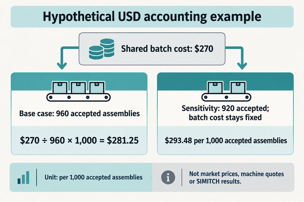
Sample joining cost below is $281.25 per 1,000 accepted assemblies ($270 batch cost / 960 accepted assemblies). The denominator takes into account rejected output. An alternative route comparison worth considering would incorporate the entire cost for the same accepted assembly specifications – which would encompass labor, electricity, tooling, equipment allocation, setup and inspection and scrap loss.
Based on assumed inputs: each number below is hypothetical USD “accounting” arithmetic, not a market price, quote for the equipment or SIMITCH production result. No raw material purchase is added, but scrap material loss is included. Setup and inspection labor are separate from processing time, and maintenance is included in equipment.
| Input | Assumed basis | Batch cost |
|---|---|---|
| Started / accepted assemblies | 1,000 / 960 | Not applicable |
| Production labor | 12 s per started assembly × $30/hour | $100 |
| Batch electricity | 15 kWh × $0.20/kWh | $3 |
| Electrode consumption | Batch allocation | $15 |
| Fixture allocation | Batch allocation | $20 |
| Equipment and maintenance | Batch allocation | $50 |
| Setup labor | Separately timed | $30 |
| Inspection labor | Separately timed | $40 |
| Scrap material loss | Batch loss | $12 |
| Total | Joining conversion plus scrap loss | $270 |
Cost per 1,000 accepted assemblies = batch cost ÷ accepted assemblies × 1,000. Thus, $270 ÷ 960 × 1,000 = $281.25. In a fixed-cost sensitivity case, accepted output falls to 920 while batch cost stays fixed, and the result becomes $293.48.
Hidden bottlenecks impact measured time and accepted output. The cycle boundaries in the case study and James L. Dillard’s electrode-maintenance discussion support keeping the following items visible in production costing.
| Activity | Record | Financial effect |
|---|---|---|
| Squeeze and hold | Complete gun cycle | Available output per hour |
| Part or robot movement | Complete assembly cycle | Handling labor and capacity |
| Tip dressing and replacement | Downtime and consumed tips | Lost time and consumables |
| Cooling and duty limits | Auxiliary energy and interruptions | Utility cost and utilization |
| Inspection and rejection | Inspection time and accepted count | Labor, scrap and denominator |
In the case of finance teams, the benefits of spot welding can be quantified where the process reaches the joint specification at a repeatable cost. Spot welding offers localized heat input and automation opportunities, but each alternative requires its own measured time, consumables and yield in the worksheet.
Industry outlook: new materials and weld quality monitoring
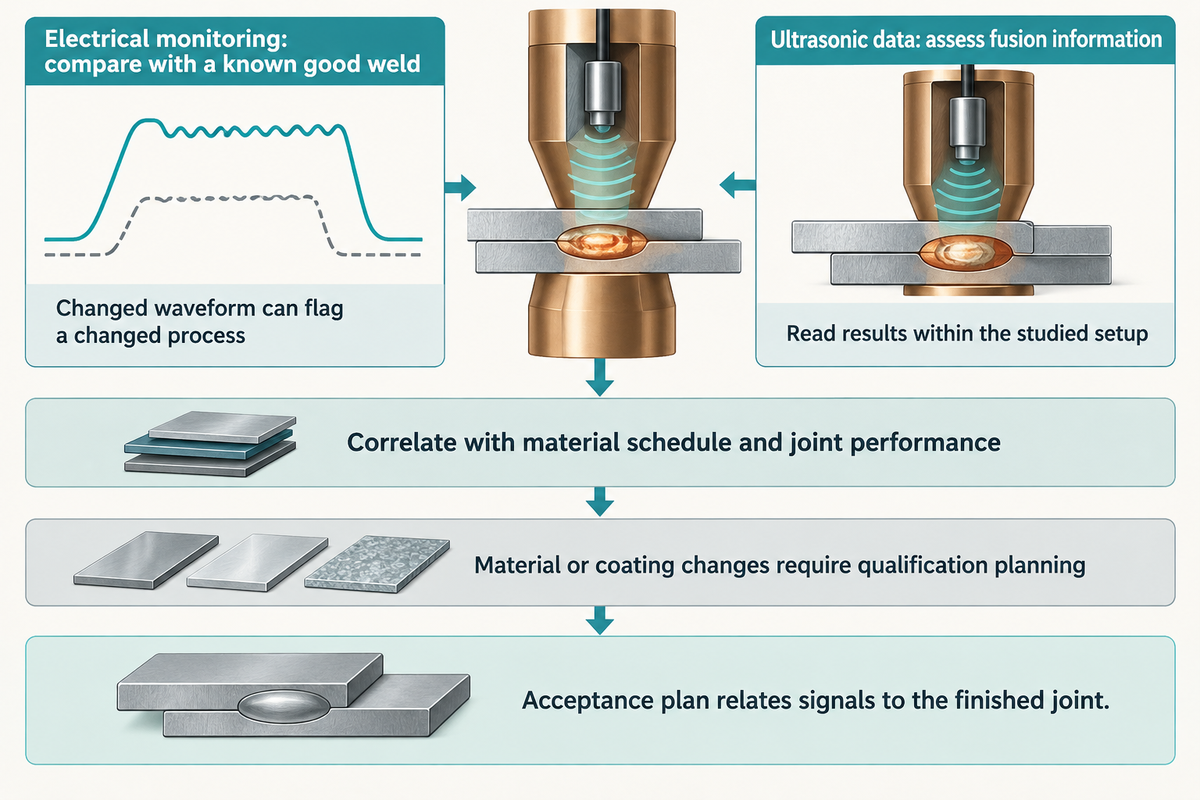
New material stacks and sensing techniques are evolving the specification of welding technology. Modern welding can monitor process signals and ultrasonics can give further data on the extent of fusion. These are best used when their readings have been correlated with the real material schedule and intended joint performance.
A 2026 ultrasonic-monitoring study used probes embedded in electrodes and automated analysis to assess molten-pool information and estimate nugget diameter. Some authors had supplier affiliations. Its application-specific results should be read within the studied setup.
Electrical monitoring also has a useful, narrower role. Mark Boyle’s technical discussion of process monitoring explains comparison with a known good weld. A changed waveform can flag a changed process; the acceptance plan establishes how that signal relates to the finished joint. A material or coating change alters that relationship and belongs in qualification planning.
Spot welding FAQ
Spot-welding terminology distinguishes the heat source, the function of the joint, and the means to create it. Tack is a positioning function. Resistance and laser are two means of providing heat.
The following answers address those and the common questions about electrodes, splash-control, and system parts before an equipment discussion.
What’s the difference between a spot weld and a tack weld?
A spot weld identifies a localized connection; a tack weld holds parts in position before later welding or assembly. Resistance spot welding forms its connection with current and electrode force. A tack describes the positioning purpose rather than one particular heat source. See our guide to tack weld purpose for preparation details.
Is spot welding hard?
Making a visible spot can be straightforward; producing repeatable acceptable joints requires control of materials, fit, current, force and electrode condition. A production operator follows a qualified setup and checks specified process indicators. Setting up that process demands suitable tooling, representative trials and an acceptance plan that addresses the actual assembly loads.
What electrode material should I use for resistance spot welding?
Use copper alloys for many steel-sheet applications; consider tungsten or molybdenum for copper-rich workpieces. Copper alloys conduct current and remove heat effectively, while different electrode materials alter the heat balance for conductive workpieces. Electrode geometry, cooling and surface condition also affect the selection and its performance during repeated production runs.
Is spot welding TIG?
No. Conventional resistance spot welding heats the contacting sheets by passing current through them under electrode force. TIG uses an arc from a tungsten electrode to heat the joint. Their heat sources, tooling arrangements and process controls are therefore different.
How can I minimise weld splash, for resistance spot weld quality and safety reasons?
Control splash by keeping contact, force, tip condition and heat input within the qualified process window. Poor fit or unstable contact can concentrate heating, while excessive current can expel molten metal. Electrode pickup and wear also alter the contact area. Follow the approved troubleshooting sequence rather than increasing current to compensate for every weak joint. Preserve the hold stage, maintain cooling and use appropriate protection against splatter. Production changes should follow the acceptance controls specified for that assembly.
Can laser welding machines be used for spot welding?
Yes. A laser can make discrete localized welds using a focused beam. Laser spot welding produces heat through optical energy, whereas resistance spot welding uses current through contacting parts. A spot-shaped joint therefore doesn’t identify the underlying welding method.
What Are the Components of a Spot Welding Machine?
A typical system includes a welding power source, controller, welding electrodes and a mechanism that applies force. A welding transformer may form part of the power system. Cooling, holders, fixtures and monitoring complete the configuration where required. Automated spot welding equipment can add robots, handling and guarding. Precision systems use weld heads suited to small connections. Welding tools and utilities must match the machine family, material stack and production duty, with their inclusion stated in the equipment quotation.
If the material and access review points toward mechanical joining, send SIMITCH the part drawing, material stack, coating and required service loads. Include the tool-access envelope and intended production rate. Discuss a mechanical joining application to compare an appropriate clinching or riveting route with the joint you need to produce.
References & Sources
- What is Spot Welding? (A Complete Welding Process Guide) TWI.
- How do I resistance spot weld aluminium alloys? TWI.
- How do clinching and self-piercing riveting compare with spot welding for sheet materials? TWI; qualitative comparison used.
- ISO 14373:2024; ISO 669:2016; DS/EN ISO 10447:2022 public catalogue scopes.
- Life Cycle Assessment of Fusion Welding Processes, A Case Study of Resistance Spot Welding Versus Laser Beam Welding Andreas Pittner and Michael Rethmeier, 2022.
- Direct RSW of Aluminium to Steel AHSS Insights.
- Shunting effect in resistance spot welding steels – Part 1: Experimental study original author abstract.
- Determination of Liquid Metal Embrittlement Crack Propagation Kinetics During Resistance Spot Welding Using In-Situ Monitoring JiUng Kim, University of Waterloo, 2026.
- Controlling the risks from welding HSE.
- Resistance welding electrodes: More for less James L. Dillard, The Fabricator; supplier-authored technical guidance.
- A resistance weld process monitoring Q&A Mark Boyle, The Fabricator; supplier-authored technical guidance.
- Automation of Ultrasonic Monitoring for Resistance Spot Welding Using Deep Learning Scott and colleagues, 2026.



WHY WE WRITE THIS
About SIMITCH
SIMITCH develops sheet-metal joining equipment for clinching, riveting, servo pressing, pneumohydraulic drive and hot-melt connection applications. Our engineering team starts with the material stack, access envelope, cycle target and acceptance method before recommending a machine route.
Founded in 2006 in Taicang, Jiangsu, SIMITCH combines research and development, in-house production and global sales. These guides turn field experience into practical decision support for process engineers, plant teams and industrial buyers.
OUR EXPERIENCE
Since 2006
Equipment engineering, machining, assembly and joint validation under one manufacturing system.
OUR EXPERTISE
Five joining routes
Clinching, riveting, SPR, precision press-fit and hot-melt connection for production lines.