Get in touch with Suzhou Simitch Machinery Co., Ltd Company

Split-Type Pneumohydraulic Cylinders: 7-Step Guide
Learn how split-type pneumohydraulic cylinders operate, how to integrate and commission them, and how to diagnose AT/HZ system issues safely.

Engineering Guide · Pneumohydraulic Systems
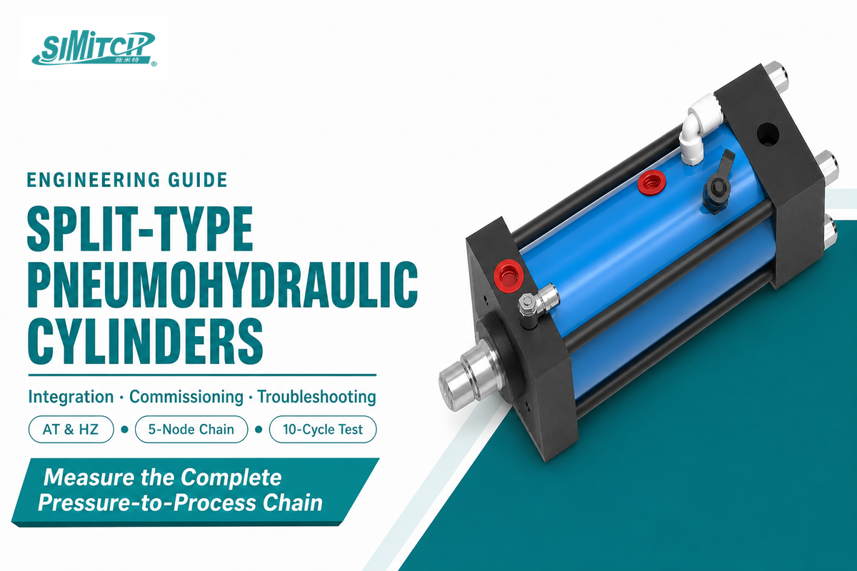
Split-Type Pneumohydraulic Working Cylinders, AT & HZ Series are easiest to specify when the whole pressure-to-process chain is treated as one machine subsystem. This guide explains the operating logic, interface checks, commissioning evidence, fault isolation, and safety boundaries that sit around the cylinder catalogue.
Quick answer
In a split-type pneumohydraulic system, the working cylinder sits at the tool and the air-oil drive sits elsewhere. Select and approve all five nodes together: plant air, drive, hydraulic line, cylinder, and tooling/controls.
TL;DR
- Split layouts solve packaging and service-access problems; they do not remove the need to match oil volume, pressure, stroke, recovery time, guidance, and controls.
- Nominal force is a starting value. Installed force and workpiece quality are acceptance-test results.
- Commission at low risk first, then record 10 representative cycles at the air, drive, line, cylinder, and tool nodes.
- Troubleshoot from the first abnormal measurement instead of changing parts in a familiar order.
- Before service, isolate every energy source, dissipate or restrain stored energy, and verify the state under the machine’s energy-control procedure.
What a Split-Type Working Cylinder Actually Changes
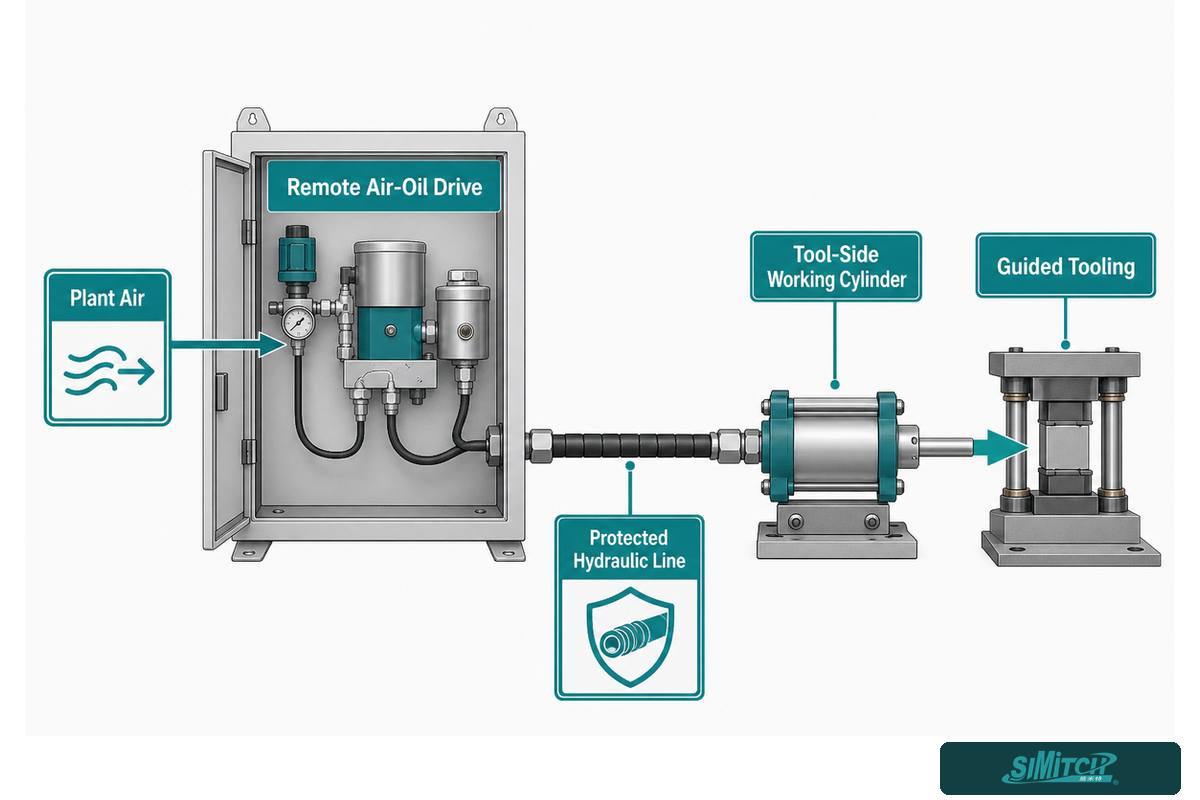
Split-type working cylinders separate the high-force actuator at the tool from the air-oil drive unit that creates hydraulic pressure. Their connecting hydraulic line lets a machine builder fit a compact cylinder into a restricted station while placing valves, service points, and the drive where access and cooling are easier.
Separation changes packaging, not physics. Compressed air still supplies the power source, hydraulic fluid transfers pressure, a piston converts that pressure into linear motion, and the piston and rod transmit mechanical force to the tooling. Every interface between those elements can change the installed result.
That boundary matters because a buyer can choose the correct cylinder bore and still miss the cycle target. Long or poorly routed lines can slow pressure build-up. Misaligned guidance can turn axial load into side load. Valve sequencing can interrupt the power stroke. Frame flexibility can absorb motion that should have reached the workpiece.
Terminology boundary. A hydraulic cylinder uses pressurized liquid as its working medium, while pneumatic systems use compressed gas for actuation. In a pneumohydraulic arrangement, the two domains meet without turning the tool-side unit into a conventional plant hydraulic cylinder. Search phrases such as “series pneumohydraulic cylinder” or “single cylinder booster” do not define the actual circuit. Drawings must show the diameter of the cylinder, the position of the piston at each transition, and which side of the cylinder receives pressure.
When a piston reciprocates inside the cylinder, single-acting cylinders, double-acting designs, and a single-rod layout produce different push and pull behavior. The cylinder end, external guide, and port arrangement affect mounting, while operating speed and high-speed approach depend on flow and control timing. Buyers seeking a compact package or long service life should still review moving components, energy efficiency, the force generated at the stated pressure, and how retraction is achieved. Naming the mechanism cannot replace these checks.
Search-language variants such as “piston and the cylinder” and “end of the cylinder” are not drawing definitions. Engineering documents should identify the piston, chamber, rod, cylinder end, and pressured side explicitly.
Packaging scenario. One machine builder has only 190 mm behind a clinching tool, while the valve cabinet has service space 1.4 m away. Placing the working cylinder at the tool and the drive unit near the cabinet resolves the envelope conflict, but it creates a documented hose route, two accessible pressure measurement points, and a recovery-time check. If the team treats the line as an afterthought, the first dry cycle may look normal while the loaded power stroke arrives late. Release therefore waits until the line, controls, guidance, and representative workpiece cycles are included in the test.
For the wider architecture choices, the pneumohydraulic drive cylinder family overview shows where split and integrated arrangements sit. This article stays with the split system and deliberately leaves AT/HZ model comparison and quotations to the commercial page.
The Five-Node Pressure-to-Process Chain
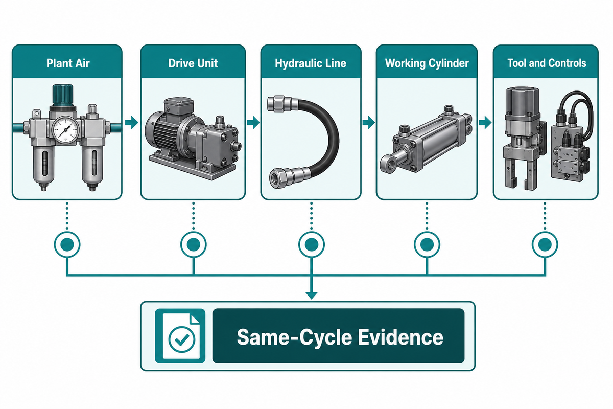
Called the Five-Node Pressure-to-Process Chain, this measurement map covers plant air, the drive unit, the hydraulic line, the working cylinder, and the tool with its controls. System readiness requires a defined input, observable output, and recorded evidence at every node under the same operating cycle.
Key takeaway
Each pressure gauge proves pressure only at its connection point. It does not, by itself, prove force, alignment, stroke completion, dwell, or workpiece acceptance at the tool.
| Node | Measurement benchmark | Abnormal signal | Next proof | Limitations / not suitable for |
|---|---|---|---|---|
| 1. Plant air | Pressure at rest and during power stroke; air quality | Dynamic pressure collapses | Measure at the machine inlet during a loaded cycle | Compressor-room gauges cannot show local restriction |
| 2. Air preparation | Regulator setting, filter condition, drain state | Unstable inlet pressure or contamination | Compare upstream and downstream readings | Fresh filters do not prove correct air quality |
| 3. Drive trigger | Command and transition timing | Late or missing pressure transition | Trend command, valve state, and pressure together | PLC output alone does not prove valve movement |
| 4. Drive output | Hydraulic pressure rise and recovery | Slow, oscillating, or capped pressure | Measure at the specified drive test point | One peak value cannot prove repeatability |
| 5. Hydraulic line | Route, fittings, restraint, bleed condition | Delay, heat, aeration, abrasion, or seepage | Compare drive and cylinder-side pressure traces | Never loosen a live fitting to test for air |
| 6. Cylinder chamber | Pressure, stroke, dwell, return | Pressure present but motion incomplete | Check load, guidance, stop position, and opposing pressure | Pressure is not a direct force measurement |
| 7. Piston and rod | Axial alignment and position | Binding, uneven wear, or slow return | Inspect guidance and load path under isolation | Cylinder rods are not external side-load guides |
| 8. Tool stack | Shut height, contact point, deflection | Correct pressure but weak process result | Measure tool position and accepted workpiece feature | Cylinder data cannot compensate for flexible tooling |
| 9. Controls | Sequence, interlocks, sensor edges, dwell | Skipped, doubled, or mistimed transition | Review a time-aligned trace | Control indication is not energy isolation |
| 10. Workpiece | Dimension, joint, mark, or pass/fail result | Drift across nominally identical cycles | Correlate result with the same cycle’s trace | One good part does not prove process capability |
How does a hydro pneumatic cylinder create high force?
Hydro pneumatic cylinders use compressed air to drive an air-oil intensifier or booster stage. Resulting hydraulic pressure acts on the area of the piston inside a cylinder, so output force rises with pressure and effective piston area. Approach motion can remain fast at low force, followed by a shorter high-force power stroke. That pressure path must still be measured at the machine because line losses, opposing loads, and tool compliance separate theoretical output from released process force.
This arrangement reduces continuous hydraulic-power demand, yet it does not make the actuator a conventional hydraulic system or remove the need to check air flow, oil volume, transition timing, and retraction force. During approach, the piston and rod move toward the workpiece before the control sequence triggers intensification. Return behavior depends on cylinder type and circuit: some designs use pneumatic return, others may use spring force or a powered chamber. That distinction changes retraction force, ports, sensors, and recovery. Treat “single acting cylinder,” “double-acting cylinders,” and “air oil cylinder” as architecture clues, then confirm the actual drawing rather than inferring motion from a search label.
Use theoretical force as the first calculation: F = P × A. For an illustrative 80 mm cylinder bore, piston area is π × 0.08² ÷ 4 = 0.005027 m². At 40 MPa, theoretical push force is about 201 kN. If a plant applies a hypothetical 0.85 system factor for its measured losses, its planning value becomes about 171 kN. That factor is not a SIMITCH rating; the installed machine must establish its own correlation.
“Treat nominal force as an input to system verification, not as a guarantee at the workpiece. The drive, line, cylinder, tooling, and controls all influence the installed result.”
When a Split Layout Fits—and When It Does Not
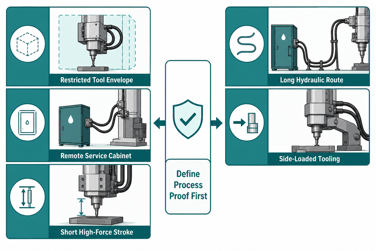
Split layouts fit when the tool area is tight but a remote location can safely house the drive, valves, and service points. They are weaker choices when the process needs high force through most of a long stroke, the hydraulic line cannot be protected, or external guidance cannot keep the load axial.
| Application category | Recommendation | Why | Next proof | Limitations / not suitable for |
|---|---|---|---|---|
| Restricted tool envelope | Shortlist split | Remote drive reduces local package size | Envelope drawing | No safe line exit or fitting access |
| Remote service cabinet | Shortlist split | Drive service stays outside tool nest | Access review | Cabinet location adds an unprotected line route |
| Short high-force finishing stroke | Good candidate | Architecture separates approach from power stroke | Travel-phase chart | High force required for nearly all travel |
| Modular station layout | Consider split | Working cylinder and drive can be packaged separately | Interface control document | Ownership between modules is unclear |
| Long hydraulic route | Validate before selection | Route affects response and service risk | Route drawing and cycle test | Uncontrolled length, bends, heat, or abrasion |
| Side-loaded tooling | Redesign guidance first | Piston and rod should transmit axial force | Load-path review | Cylinder rod used as the tool guide |
| Fast repeated cycles | Test recovery margin | Drive must recover before the next power stroke | 10-cycle trace | Cycle time leaves no stable recovery window |
| Multiple cylinders | Engineer the circuit | Split packaging does not create synchronization | Timing and load-share test | Assumed equal motion without control evidence |
| Poor service access | Change layout | Bleed, inspection, and isolation need access | Maintenance walkdown | Fittings hidden behind the hazard zone |
| Uncertain workpiece acceptance | Define process proof first | Pressure alone cannot approve the part | Measurement plan | No measurable pass/fail feature |
When should you not buy a split-type cylinder?
Do not treat a split system as the default when remote packaging has no clear benefit. Integrated boosters can reduce external hydraulic interfaces in some layouts. Conventional hydraulic systems may fit better when high force is needed across long stroke lengths.
When force and motion must be regulated continuously, or the plant already supports hydraulic power and maintenance, a conventional hydraulic system may also be a better fit.
Buying a split arrangement is premature while tool guidance, energy isolation, hose protection, or workpiece acceptance remain undefined. Those are design inputs, not installation details to solve after delivery. Next comes an interface review, not a larger cylinder.
Match the Circuit Before You Match a Model
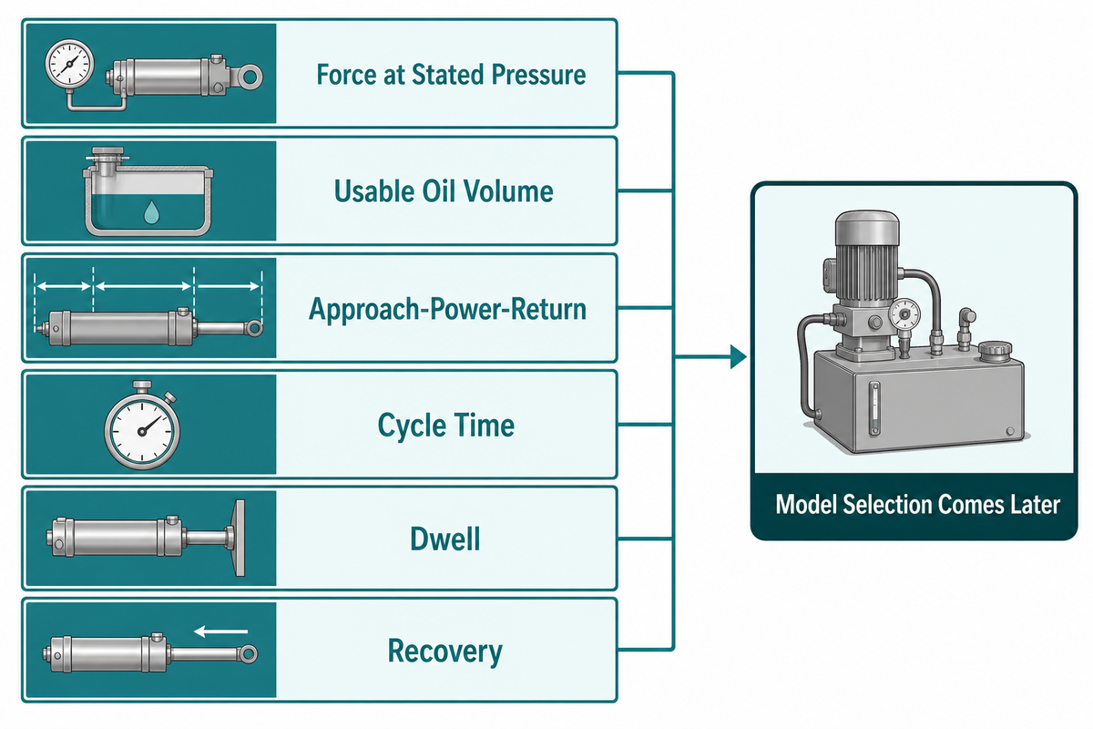
Circuit matching starts with force at a stated pressure, usable oil volume, the approach–power–return travel profile, cycle time, dwell, and recovery. Model selection comes later. All working-cylinder, drive-unit, valve, port, line-route, sensor, and tooling decisions must support the same motion and load sequence.
Begin with the force window, not a single maximum. Record the minimum force that produces an accepted part and the upper limit that protects the tool, workpiece, and frame. Then specify where the power stroke begins, how much high-force travel is needed, how long the dwell lasts, and what retraction force or spring force must be overcome.
Next, connect pressure to the actual piston area. Head-end area determines theoretical push force; the cylinder rod end has a smaller effective annular area, so pull or retraction force is different. Friction, pressure loss, opposing load, seal condition, tool geometry, and frame deflection reduce the result available at the process.
For exact family data and the engineering handoff, use the split-type pneumohydraulic working cylinder specifications. Keeping model tables on that page gives the commercial page one clear job while this guide answers implementation questions.
Pressure must stay beside every commercial force value. The current page lists the AT family at 13–1030 kN under a 400 bar basis and the HZ family at 48–492 kN under a 250 bar basis. Those four figures belong to the family shortlist; installed acceptance still comes from the completed machine.
What information is needed before selecting a working cylinder?
Provide the accepted process force window, approach travel, high-force stroke, return travel, cycle time, dwell, plant air under dynamic load, mounting envelope, hose route, external guidance, sensor plan, control sequence, tool deflection, safety concept, and workpiece acceptance method. Missing inputs should be marked open, not replaced with assumptions. The same data lets a supplier separate approach travel, power-stroke oil volume, return demand, sensing, and acceptance criteria before proposing a model or accessory package.
Selection scenario. One team asks for a 120 mm stroke because that is the distance from the home position to the part. Drawing review shows that only the final 6 mm needs high force; the preceding 114 mm is approach travel. That distinction changes the circuit discussion. Usable oil volume, transition point, drive recovery, and sensor sequence must be checked against a 4.2 s target cycle and a 0.6 s dwell. Ordering from the 120 mm number alone could produce a cylinder that fits mechanically but cannot repeat the required power-stroke timing. Afterward, the corrected RFQ separates all three travel phases and attaches the timing diagram.
Mounting, Hose Routing, and Tool Guidance
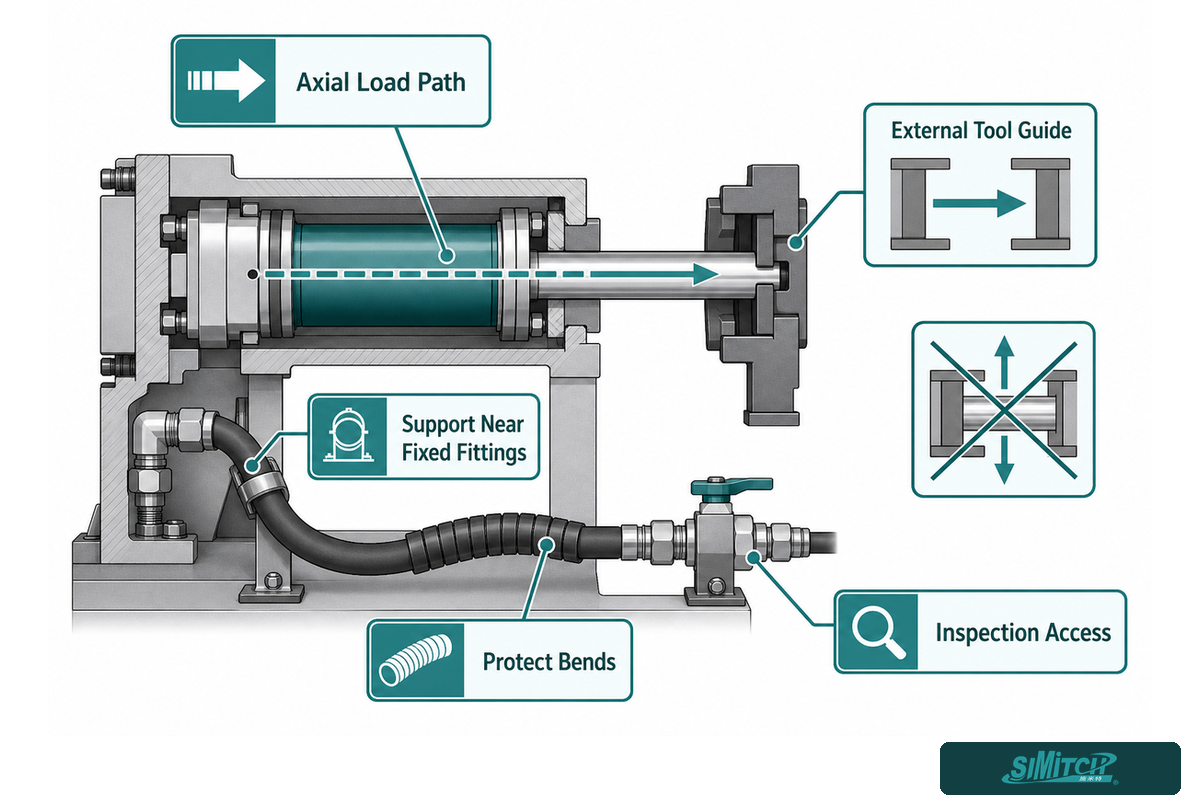
Mounting must keep cylinder force axial, while an external guide carries side load and tool reaction. Hose routing must protect the hydraulic line from tight bends, abrasion, heat, moving pinch points, and unsupported fittings. Service access must allow safe inspection, measurement, and approved bleeding without entering an energized hazard zone.
Do
- Align the load path through the tool guide.
- Support the line near fixed fittings.
- Protect bends from abrasion and heat.
- Leave access for inspection and measurement.
- Document the approved bleed point.
Don’t
- Use the rod as the tooling guide.
- Let a moving hose rub the frame.
- Hide fittings behind fixed guards.
- Twist the line to make a port fit.
- Loosen a pressurized connection.
Before startup, compare the released drawing with the physical machine. Check the mounting face, fastener strategy, rod-end connection, tool guidance, hard stops, line restraint, bend condition, fitting orientation, sensor targets, bleed access, and the zero-energy service position. Photograph any deviation and close it through the change process before the first loaded cycle.
This walkdown also checks that the cylinder cap, cylinder barrel, rod end, and inlet and outlet ports remain accessible under the planned guard arrangement. Access does not mean a technician may work while energized; it means the approved isolation and verification procedure can be executed without dismantling unrelated machine sections.
A 10-Cycle Commissioning Protocol
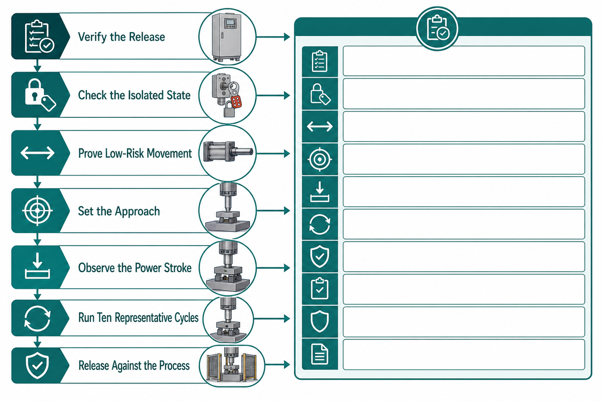
Called the 10-Cycle Commissioning Card, this protocol turns a successful first stroke into repeatable evidence. It checks the released build, safe low-risk motion, pressure transition, stroke and dwell, dynamic air, hydraulic response, return, workpiece result, leakage, and recovery across ten representative cycles using plant-specific acceptance limits.
- Verify the release — match the drawing, cylinder, drive, line, fittings, sensors, guards, and energy-control procedure.
- Check the isolated state — perform fill, precharge, and inspection tasks only under the approved machine procedure.
- Prove low-risk movement — confirm direction, stops, sensor order, and clearance without a representative process load.
- Set the approach — verify approach speed and the transition position without masking impact or tool contact.
- Observe the power stroke — record dynamic air, hydraulic rise, stroke, dwell, and control timing together.
- Run ten representative cycles — use the same workpiece, tooling, settings, and measurement method for the sample.
- Release against the process — accept only when machine safety and workpiece criteria both pass.
| Cycle | Air during stroke (bar) | Hydraulic peak (bar) | Power stroke (mm) | Cycle time (s) | Part result / notes |
|---|---|---|---|---|---|
| 1 | Record | Record | Record | Record | Record |
| 2 | Record | Record | Record | Record | Record |
| 3 | Record | Record | Record | Record | Record |
| 4 | Record | Record | Record | Record | Record |
| 5 | Record | Record | Record | Record | Record |
| 6 | Record | Record | Record | Record | Record |
| 7 | Record | Record | Record | Record | Record |
| 8 | Record | Record | Record | Record | Record |
| 9 | Record | Record | Record | Record | Record |
| 10 | Record | Record | Record | Record | Record |
Blank fields are intentional. Responsible plant personnel supply the released limits, calibrated instruments, sampling method, and part-acceptance criteria. Ten cycles are a commissioning screen, not a statistical capability study.
Formatting example only. A hypothetical record might show dynamic air changing from 6.0 bar to 5.6 bar, hydraulic peak from 250 bar to 248 bar, power stroke from 6.0 mm to 5.9 mm, cycle time from 4.2 s to 4.9 s, and dwell from 0.60 s to 0.58 s. Another project could use 7.0 bar, 400 bar, 12 mm, 3.8 s, and 0.40 s. None of these values is a recommendation; the point is to keep units, measurement locations, and cycle identity attached to every entry.
Instrument records should also state resolution and range. Formatting examples include 0.1 bar, 1 bar, 0.1 mm, 0.01 s, 0.1 kN, 1 MPa, 1 °C, 5 ms, 10 ms, and 0.5 %; actual requirements come from the plant measurement plan and selected hardware.
Commissioning scenario. Three unloaded cycles return cleanly, so the team adds the representative tool and part. Cycle 1 reaches the planned pressure, but Cycle 6 takes 0.7 s longer and the dynamic machine-inlet air trace dips at the start of the power stroke. Hydraulic peak remains close to target. That pattern directs the team upstream before anyone changes the cylinder. They inspect the local regulator, valve flow path, and supply restriction, then repeat the complete 10-cycle card after correction. Release uses the new cycle set; those early successful strokes remain diagnostic evidence, not proof of acceptance.
Troubleshoot by Measured Node, Not by Guessing
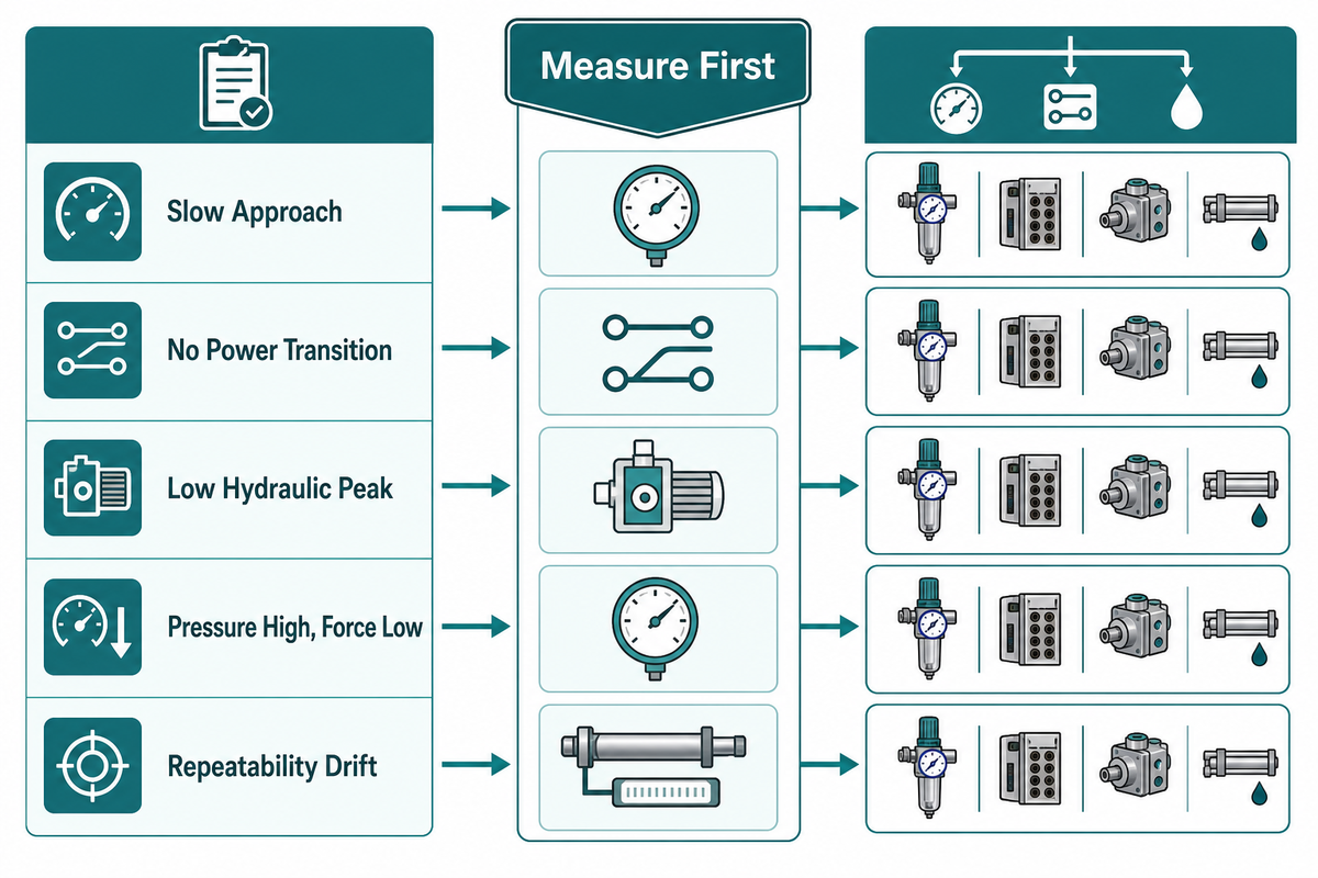
Our Symptom-to-Measurement Triage Matrix starts at the first abnormal signal and moves one node upstream or downstream. This method separates air-supply, valve, drive, line, cylinder, tooling, and control faults before parts are removed. It also keeps live-line loosening and guard bypass out of the diagnostic routine.
| Symptom | Measure first | Compare next | Likely branch | Limitations / not suitable for |
|---|---|---|---|---|
| Slow approach | Dynamic air at machine inlet | Command-to-motion timing | Supply, regulator, valve, restriction | Do not raise pressure to hide a restriction |
| No power transition | Trigger signal and position | Drive hydraulic output | Sensor, sequence, valve, drive | PLC output does not prove valve shift |
| Low hydraulic peak | Drive-side hydraulic pressure | Dynamic air and settings | Air supply, drive, relief path | Use rated test points only |
| Pressure high, force low | Cylinder-side pressure and tool position | Workpiece result and frame motion | Guidance, tool, load path, deflection | Gauge pressure is not a load-cell result |
| Repeatability drift | Ten-cycle aligned trace | Air, pressure, timing, part result | Recovery, heat, air, controls, process | One cycle cannot show drift |
| Slow return | Return command and position time | Opposing pressure and mechanical load | Valve, exhaust, binding, return load | Do not pull the rod by hand while energized |
| Incomplete stroke | Position at pressure transition | Stop, tool contact, available oil volume | Setup, volume, obstruction, sensing | Never bypass a stop or interlock to gain travel |
| Aeration clue | Pressure trace and approved visual points | Recent service and line condition | Fill, bleed, leak, fitting, route | Do not crack a fitting under pressure |
| External leakage | Leak location under safe inspection | Hose, fitting, seal, surface condition | Connection or component service | Never search with bare hands |
| Noise or heat change | Cycle timing and pressure waveform | Baseline sound, temperature, routing | Restriction, aeration, friction, duty | Do not invent a universal temperature limit |
Useful diagnostic notes record the symptom, cycle number, command state, pressure point, position, workpiece result, and what changed from the released baseline. “Cylinder weak” is not a diagnosis. “Cylinder-side pressure matched baseline, but tool position stopped 1.8 mm early after contact” is a useful branch point.
Maintenance and the Zero-Energy Boundary
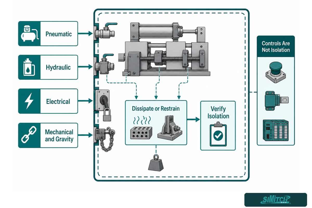
Maintenance starts with a machine-specific zero-energy boundary, not a stopped piston. Isolate pneumatic, hydraulic, electrical, mechanical, and gravity hazards; dissipate or restrain stored energy; then verify isolation under the site’s authorized procedure. Stop buttons, interlocks, and PLC indications are control information, not energy-isolating devices.
OSHA’s typical lockout/tagout procedure specifically addresses stored or residual hydraulic and pneumatic energy and requires verification before work. Its energy-control circuitry guidance also explains why control circuits cannot replace energy isolation.
System designers should review both ISO 4413 for hydraulic fluid power and ISO 4414 for pneumatic fluid power in the context of the complete machine. These standards do not turn a component into a certified machine. Risk assessment, controls, guards, instructions, and validation remain project responsibilities.
Routine work can then be organized by condition and duty: inspect hoses and fittings for damage or leakage; review mounting and external guidance; compare sensor timing with the baseline; check contamination or aeration clues; verify that the line remains restrained and protected; and trend cycle or pressure changes. Use the component instructions and the plant’s environment to set intervals. Any universal “every 500 hours” claim would be guesswork without duty and contamination data.
Point-of-operation safety is separate from energy isolation. OSHA’s machine-guarding rule requires protection appropriate to the hazard. Cylinder selection cannot replace the guard, safety function, or validation for the assembled machine.
Common mistake
Never loosen a hydraulic fitting, open a line, reach through a guard, or bypass an interlock to “see what happens.” Stop, isolate, control stored energy, verify the state, and use rated measurement points and the approved service method.
Prepare the Engineering Handoff
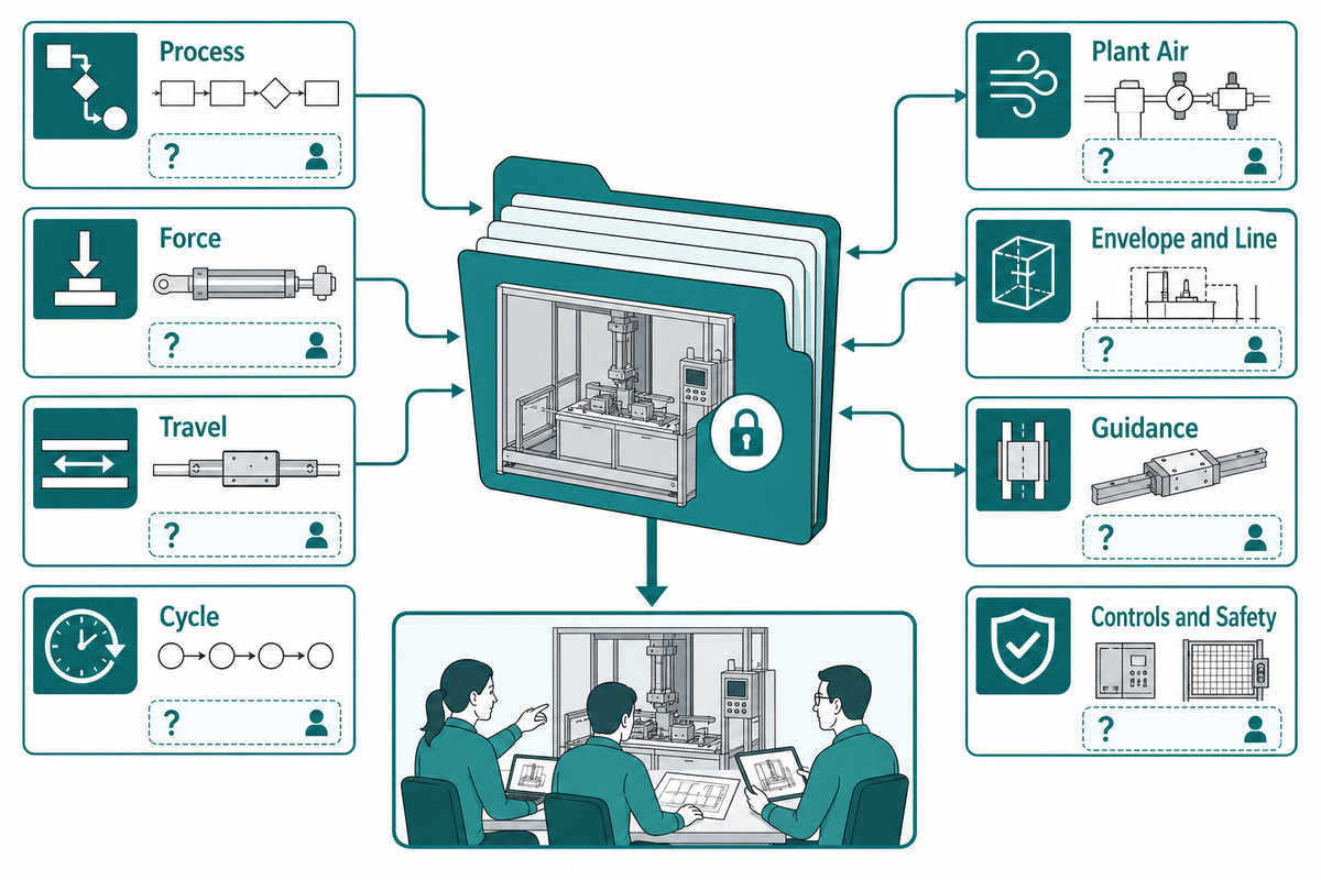
Effective engineering handoffs give the supplier and machine builder one controlled set of process, motion, utility, layout, guidance, sensing, safety, and acceptance inputs. Each handoff should identify owners and open questions, so a missing limit is resolved by test or design review rather than hidden inside a model assumption.
RFQ checklist — copy these into your quote request:
| Parameter | Required input | Why it matters | How to verify |
|---|---|---|---|
| Process | Material, operation, accepted feature | Defines the real output | Sample part and drawing |
| Force | Minimum, nominal, and maximum at the process | Protects quality and tooling | Test method or correlated load measurement |
| Travel | Approach, power, and return in mm | Separates motion phases | Released motion diagram |
| Cycle | Cycle time, dwell, shifts, recovery window | Sizes duty and timing margin | Timing chart and 10-cycle test |
| Plant air | Dynamic pressure, quality, local connection | Defines usable input | Loaded machine-inlet measurement |
| Envelope and line | Mounting space, port direction, protected route | Controls packaging and response | 3D model and route drawing |
| Guidance | External guide, load path, frame stiffness | Keeps force axial | Load-path and deflection review |
| Controls and safety | Sensors, sequence, guards, isolation, acceptance | Closes machine responsibility | Risk assessment and validation plan |
Send that package for an AT and HZ configuration review. Readers evaluating the supplier can also review SIMITCH manufacturing and application-engineering background before the project discussion.
Bring the five-node data to the first review
Share the process, motion phases, dynamic air, line route, guidance, control sequence, and acceptance method. Engineering discussion can then focus on evidence instead of filling gaps with a larger safety factor.
Frequently Asked Questions
These answers cover the operating and integration questions that sit around the commercial AT/HZ selection page. They are intentionally general because actual force, stroke, pressure, port, line, duty, and safety decisions depend on the selected components and the assembled machine.
What is a hydro pneumatic cylinder?
Hydro pneumatic cylinders use compressed air as the input power and hydraulic fluid to transmit amplified pressure to a working piston. They combine pneumatic approach and control characteristics with a short hydraulic high-force stroke. Exact arrangements may be integrated or split, and installed output still depends on the complete circuit and tool. A supplier’s force table must retain its stated pressure basis, because force values copied without pressure can lead to the wrong family comparison.
How is a split-type system different from an integrated booster cylinder?
Split systems place the working cylinder and air-oil drive unit in separate locations connected by a hydraulic line. Integrated designs package more of the force-generation stages together. Their external connection count changes installation and service planning for the machine as a whole.
Split layouts can help a restricted tool envelope or remote service plan, while integrated layouts may reduce external hydraulic interfaces. Neither option is universally better; the machine’s travel, duty, route, guidance, and access decide.
Can one pressure value predict force at the workpiece?
No. Pressure multiplied by effective piston area gives theoretical cylinder force at that chamber, but the workpiece result also reflects pressure loss, friction, opposing pressure, seal condition, alignment, tool geometry, frame deflection, and the actual contact point. Use a pressure reading as one node in a correlated acceptance test, not as standalone proof of process force. A useful release test pairs the pressure value with cylinder position, contact timing, and the accepted workpiece feature from the same production cycle.
What causes a split pneumohydraulic cylinder to return slowly?
Possible branches include inadequate air flow, a valve or exhaust restriction, opposing hydraulic pressure, mechanical binding, side load, an incorrect control transition, or a return load that exceeds the available retraction force. These branches do not produce the same pressure trace.
Record the return command, position-time trace, air pressure, and opposing pressure before isolating the machine for mechanical inspection.
How should air be removed from the hydraulic side?
Use only the fill and bleed procedure, fluid, orientation, ports, and isolation steps specified for the selected drive and cylinder assembly. Never loosen a live fitting as a diagnostic shortcut. Bleeding changes the stored-energy state and may expose personnel to injection, movement, or spill hazards, so it belongs inside the machine’s authorized service procedure. The approved method should name how residual pressure is checked and how unintended motion is restrained before any connection can be opened.
When should the AT/HZ page be used instead of this guide?
Use this guide to prepare the system inputs, commissioning plan, diagnostic measurements, and safety questions. Use the commercial AT/HZ page when you need current model ranges, pressure bases, dimensions, mounting choices, configuration review, or a quotation. That keeps commercial selection intent on its dedicated page.
Together, the pages serve different search intent: this one supports engineering understanding; the commercial page supports product selection and inquiry. The family page keeps the 400 bar and 250 bar rating bases beside their respective force tables.
References & Sources
Load-bearing technical and safety statements in this guide use first-party product documentation and primary standards or government sources. Commercial competitor pages were reviewed for content gaps but are not used as evidence.
- SIMITCH — Split-Type Pneumohydraulic Working Cylinders, AT & HZ Series
- ISO 4413 — Hydraulic fluid power: General rules and safety requirements
- ISO 4414 — Pneumatic fluid power: General rules and safety requirements
- OSHA 1910.147 Appendix A — Typical minimal lockout procedure
- OSHA — Energy control circuitry prohibition
- OSHA 1910.212 — General requirements for all machines
Engineering note: examples in this article illustrate a method, not a product rating or machine-safety approval. Final selection and validation must use the released component documentation and the assembled machine’s risk assessment, measurements, and acceptance plan.



WHY WE WRITE THIS
About SIMITCH
SIMITCH develops sheet-metal joining equipment for clinching, riveting, servo pressing, pneumohydraulic drive and hot-melt connection applications. Our engineering team starts with the material stack, access envelope, cycle target and acceptance method before recommending a machine route.
Founded in 2006 in Taicang, Jiangsu, SIMITCH combines research and development, in-house production and global sales. These guides turn field experience into practical decision support for process engineers, plant teams and industrial buyers.
OUR EXPERIENCE
Since 2006
Equipment engineering, machining, assembly and joint validation under one manufacturing system.
OUR EXPERTISE
Five joining routes
Clinching, riveting, SPR, precision press-fit and hot-melt connection for production lines.