Get in touch with Suzhou Simitch Machinery Co., Ltd Company

Gas-Liquid Booster Cylinders, BS & BT Series: Complete Guide

Updated August 20, 2026
Gas-Liquid Booster Cylinders, BS & BT Series combine fast pneumatic travel with a short, hydraulically intensified work stroke. Rather than asking only “How much force is in the catalogue?”, determine whether the actuator, air supply, tooling, controls and workpiece can deliver a repeatable result at production duty.
This guide explains that engineering path. It covers terminology, operating sequence, pressure boundaries, force delivery, integration, commissioning and evidence-led troubleshooting. Published configurations, model data, dimensions and application-review inquiries remain on the existing BS & BT solution page. That separation keeps this guide focused on engineering decisions while the solution page carries the model-specific details.
The short answer
Use a gas-liquid booster cylinder when the machine needs rapid approach plus a short high-force linear operation and when the full cycle can be verified under real supply, tooling and workpiece conditions. Do not choose from force alone. Define travel, power-stroke length, duty, contact position, dynamic pressure, load path, sensing and acceptance evidence together.
What Is a Gas-Liquid Booster Cylinder, and What Is It Not?
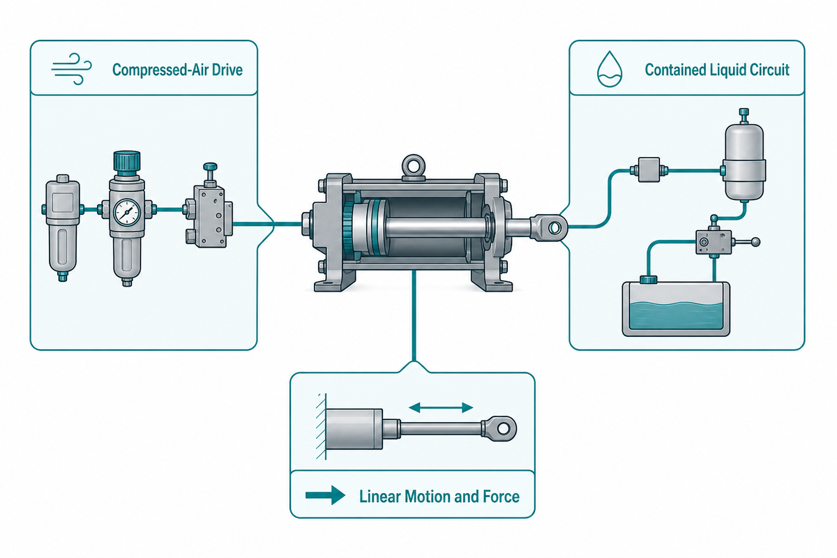
In this context, a gas-liquid booster cylinder is a linear air-over-oil actuator. Compressed air provides the drive energy, while a contained liquid circuit transfers intensified pressure during the short working portion of the stroke. It produces controlled linear motion and force at a rod or tooling interface; it isn’t equipment for filling bottles or increasing the pressure of a process gas.
Using “booster” without the actuator context creates a serious search and purchasing mismatch. Many pages use it for pumps that raise nitrogen, hydrogen or another gas from an inlet pressure to an outlet pressure. Other devices intensify liquid pressure for a remote circuit.
Those categories may share pressure-ratio vocabulary, but they do different jobs and require different application data.
Conventional hydraulic cylinders driven by a hydraulic power unit form another separate architecture. That route may fit better when the motion profile, continuous force demand, thermal load or plant infrastructure calls for it. Choose the category before choosing the model.
How the Fast Approach, Power Stroke and Return Work
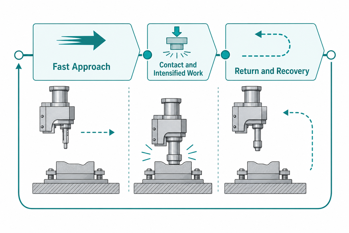
Picture the cycle as a three-part timeline: approach, intensified work and return. Exact valve arrangement and transition logic depend on the installed unit, so the model manual and machine design remain controlling. Used this way, the generic sequence gives every buyer and service team the same language.
1. Fast approach
Compressed air moves the piston and tooling toward the workpiece. This portion covers most of the travel at comparatively low force. Engineering teams should look for smooth motion, a repeatable contact or transfer position and enough point-of-use flow that approach time doesn’t drift when other air users come online.
2. Contact and intensified work stroke
After the tool reaches the defined contact condition, the booster stage raises liquid-side pressure for the shorter working displacement. Depending on the process, the result may be a formed dimension, a clinched joint, a pressed component position or another declared acceptance characteristic. Pressure rise is an intermediate event; the accepted workpiece result is the purpose of the cycle.
3. Return and recovery
Return motion retracts the actuator while the circuit resets for the next cycle. Recovery belongs in the cycle-time budget. During an isolated test, a unit can look acceptable and then become inconsistent when the next cycle begins before pressure, valve state or fluid conditions have recovered.
Record these phases separately. “The cylinder is slow” doesn’t reveal whether the delay appears in travel, transition, pressure build, dwell, retraction or recovery. Once the slow phase is visible, the investigation can stay inside the approved measurement and service boundary.
The Three-Pressure Boundary Check
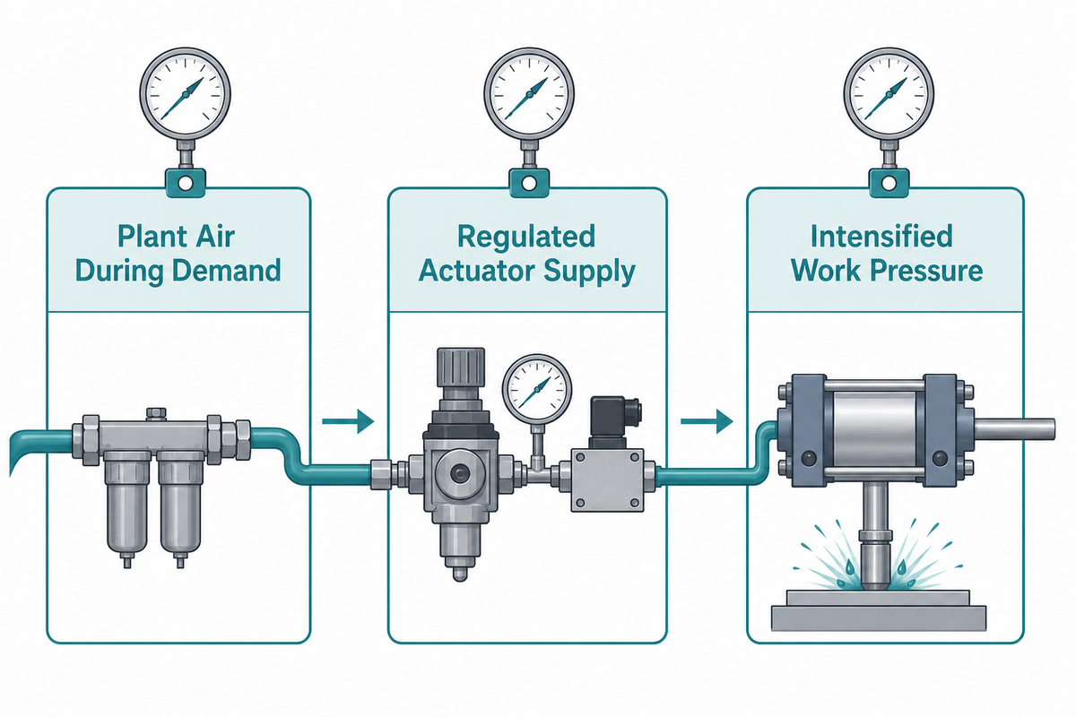
One regulator reading can’t describe the entire actuator cycle. Separate plant supply, dynamic actuator supply and intensified liquid-side pressure. Each boundary answers a different question, and readings taken at different locations or times aren’t interchangeable.
Boundary A, plant air available to the machine
Measure the utility condition while the production cycle is demanding flow. An idle header reading doesn’t show whether shared demand, storage, distribution losses or local restrictions affect the machine.
Boundary B, regulated pressure available at the actuator
Measure close to the relevant point of use during approach and transition. This boundary captures losses across local treatment, valves, tubing and fittings without assuming which component is responsible.
Boundary C, intensified liquid-side pressure during the work stroke
Observe the pressure event together with position, control state and workpiece result. Without its timing and measurement location, a pressure value can’t prove delivered tooling force.
U.S. Department of Energy compressed-air systems guidance treats pressure, leaks, controls, storage, system analysis and preventive maintenance as connected system questions. That supports measurement discipline, not a universal energy-saving claim for a cylinder.
For a useful test record, write down the instrument location, range, units, sampling method and cycle phase. If a gauge moves from upstream to downstream of a valve, the new reading belongs to a new boundary. Don’t compare the values as if nothing changed.
Why Force Alone Cannot Select the Cylinder
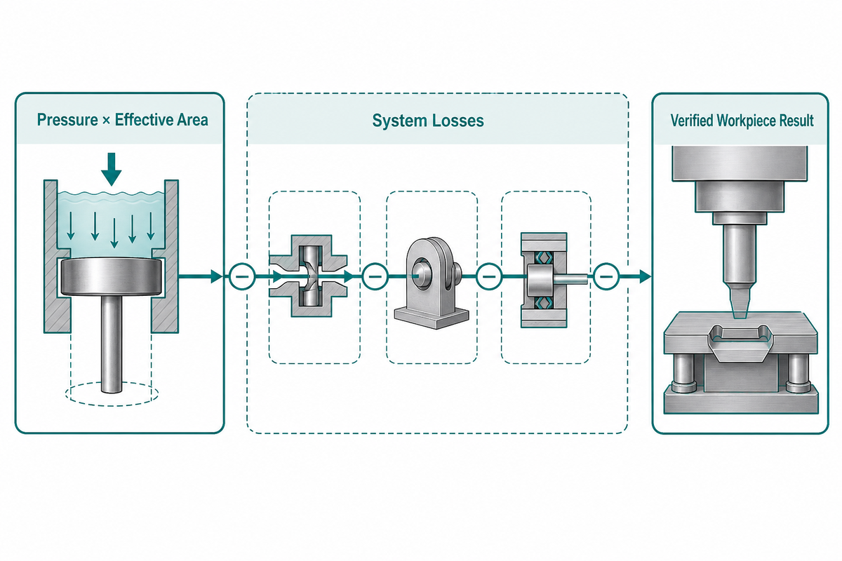
Catalogue force is reference-condition data, not proof of force at the tooling. At a conceptual level, delivered force depends on effective working pressure and effective area, then loses margin through friction, pressure drop, back pressure, alignment, tooling compliance and machine-frame deflection. What reaches the workpiece reflects the entire load path, not the catalogue column.
Delivered force ≈ effective pressure × effective area − system losses
This relationship is a reasoning aid, not a sizing calculation. Pressure ratio describes ideal intensification behavior under stated conditions. By itself, it doesn’t account for plant pressure sag, valve-flow limits, contact position, seal friction, side load, tool stiffness or the acceptance limit of the process.
Start selection with a load case: required result, working displacement, approach travel, contact tolerance, desired cycle timing, tooling geometry and the permitted force window. If force must be verified or controlled, define where the measurement occurs and how it relates to the workpiece result.
Engineering stop rule: as a conservative rule for this guide, if the process misses its acceptance limit, don’t increase pressure merely because the regulator has unused range. First verify the approved operating limit, dynamic supply, transition point, load path and tooling condition.
Where an Integrated BS/BT Architecture Fits, and When to Review Another Route
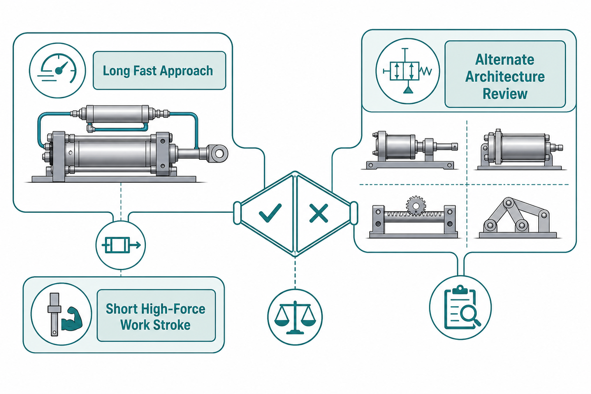
Use integrated gas-liquid booster architectures if the working duty cycle calls for long, fast approach travel then a shorter high-force work stroke, and air service is available at the machine. Smaller self-contained systems may also negate the requirement for a dedicated hydraulic power unit. Those are good questions, not necessarily advantages.
Consider other architecture if high force is required through a long stroke, force must be continuously modulated through a complex profile, recovery isn’t feasible, heat management can’t be provided in the available envelope, the facility air system isn’t stable, or the process requires a different level of motion and data control. A servo-electric or traditional hydraulic system may then warrant consideration.
Choosing between integrated and separated arrangements also affects installation envelope, tubing, service access and component placement. An integrated versus split configuration guide frames that architecture decision without replacing a model-specific review.
| Application signal | Why BS/BT may fit | What still needs proof |
|---|---|---|
| Long approach, short working displacement | Matches the fast-travel and intensified-work sequence | Contact window, power-stroke length and cycle timing |
| High linear force without a separate power unit | Air-over-oil intensification may suit the machine layout | Dynamic air condition, thermal behavior and delivered process result |
| Repeatable pressing or joining task | A defined contact-to-force sequence can be commissioned | Tooling stiffness, alignment, sensors and acceptance method |
Duty Cycle, Air Demand, Heat and Recovery Time
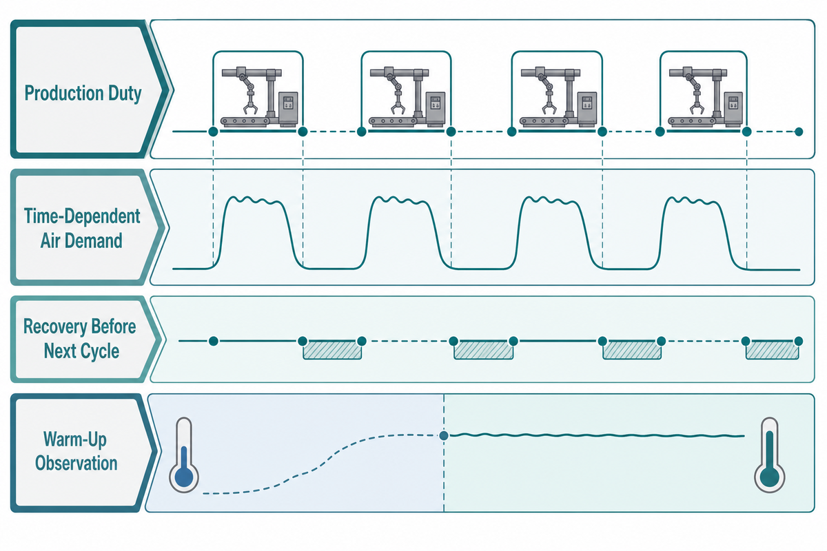
Duty cycle alters the engineering solution. Log cycles per minute, working time, standby periods, shift pattern and maximum expected run length. Then verify the complete cycle under that condition. A cylinder that performs sporadic tests may not retain the same approach time, pressure buildup or return pattern in production.
Air demand is also time-dependent. Header pressure may remain acceptable while a local restriction limits flow during rapid travel. Conversely, a stable point-of-use pressure doesn’t prove that recovery, control timing or the workpiece load is correct. The three-pressure check and cycle timeline must be interpreted together.
The DOE’s official compressed-air systems page lists resources on analyzing a system, stabilizing system pressure and preventive maintenance. For this guide, the reason for pairing point-of-use pressure with cycle timing is the risk of mistaking a time-dependent restriction for an adequate air supply; that is a conservative troubleshooting choice, not a universal energy or thermal claim.
Include temperature in the observation set, but let the installed product documentation, declared ambient conditions and measured warm-up behavior control the decision. Don’t assign a universal thermal limit from a general article. If cycle time or workpiece result changes between cold start and stable production, preserve both traces for application review.
For a useful duty study, compare at least three declared states: start-up, stable production and the most demanding permitted run. Counts and durations should come from the application, not from a generic rule. Measure approach, work stroke, return and recovery separately in each state.
Machine Integration Checklist
Integration should turn the process requirement into a traceable set of mechanical, pneumatic, hydraulic and control envelopes. Consult the list below to facilitate discussion with the machine integrator and actuator supplier. It isn’t a step-by-step guide to installation.
- Define the load case: workpiece result, permitted force or displacement window, load direction and abnormal condition.
- Map the stroke profile: total approach travel, contact tolerance, useful power-stroke length and return clearance.
- State the duty: cycle rate, on-time, shift pattern, recovery allowance and warm-up behavior.
- Record the utility: plant and point-of-use dynamic air conditions, treatment requirements and expected simultaneous demand.
- Review mounting and load path: cylinder alignment, external guidance, tool mass, eccentric load and frame stiffness.
- Identify sensing: home, approach, contact/transition, work-complete and return evidence needed by the sequence.
- Define controls: valve states, interlocks, reset behavior, fault response and permitted manual mode.
- Describe the environment: ambient range, contamination, washdown or corrosion exposure and service access.
- Agree on acceptance: workpiece result, measurement method, repeatability window and retained commissioning record.
- Plan maintenance: permitted inspection points, isolation method, consumables, documentation and escalation path.
Machine guarding and control of hazardous energy are finished-machine responsibilities. Official scopes for ISO 4413 and ISO 4414 cover general safety rules for hydraulic and pneumatic fluid-power systems and components on machinery. Referencing them does not certify a particular component or completed machine.
Discuss the integration checklist
The Contact-to-Force Proof Protocol for Commissioning
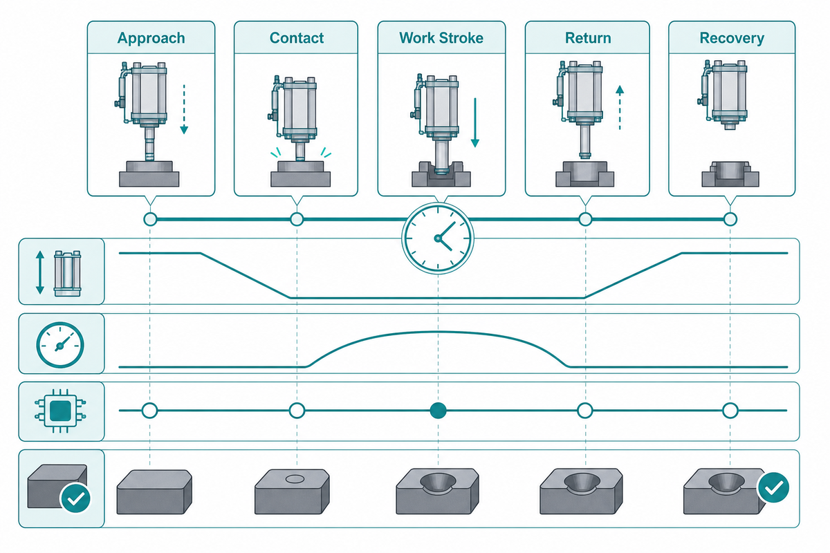
Commissioning should connect the contact event to pressure, motion and the accepted workpiece result. This creates a known-good reference that quality, maintenance and controls teams can use later. It is a practical evidence framework, not a universal acceptance standard.
For this guide’s commissioning record, use synchronized timestamps. Captured without position, a pressure peak can occur before or after the intended contact event. Workpiece results recorded without tool and material identification may not be comparable. Sensor state without the commanded valve state can’t show whether control or motion led the change.
As a practical commissioning method, retain a sample of comparable cycles rather than declaring one favorable run as proof. Required sample size and acceptance rules belong to the process owner and quality plan. If the material, tool, utility condition, measurement location or control recipe changes, label the new baseline rather than silently merging it with the old one.
Troubleshooting by Cycle Evidence
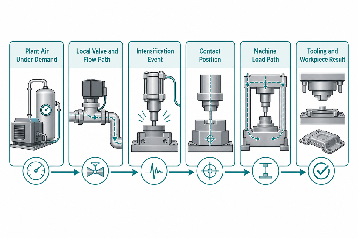
For this review sequence, begin with the phase that changed. This avoids swapping parts or adjusting pressure before the evidence identifies the relevant branch. What follows is a review sequence, not a model-specific fault code.
The Force-Delivery Constraint Chain
Plant air under demand → local valve and flow path → intensification event → contact position → machine load path → tooling and workpiece result
| Symptom | Evidence first | Interpretation boundary |
|---|---|---|
| Slow approach | Dynamic point-of-use pressure, valve command, position and external binding | Separate utility restriction from mechanical or control delay |
| Normal travel, weak work result | Contact position, pressure event, work displacement and tool condition | Do not infer delivered force from a static regulator |
| Inconsistent transition | Sensor state, commanded valve state, position and pressure rise on one clock | Determine whether contact, sensing or pressure build moved first |
| Slow return or recovery | Return time, home state, recovery interval and temperature trend | Separate visible retraction from readiness for the next cycle |
| Leakage or abnormal noise | Location, timing, contamination, rod/tool condition and recent changes | Stop if continued operation may create uncontrolled motion or damage |
If catalogue force appears adequate but the process remains weak, walk the chain in order. Local pressure drop, late contact, misalignment or flexible tooling can each reduce the useful result without changing the catalogue. As a conservative service boundary for this guide, if evidence points outside permitted service actions or the cause remains uncertain, preserve the trace and involve the responsible engineer or manufacturer.
Maintenance and Machine-Level Safety Boundaries
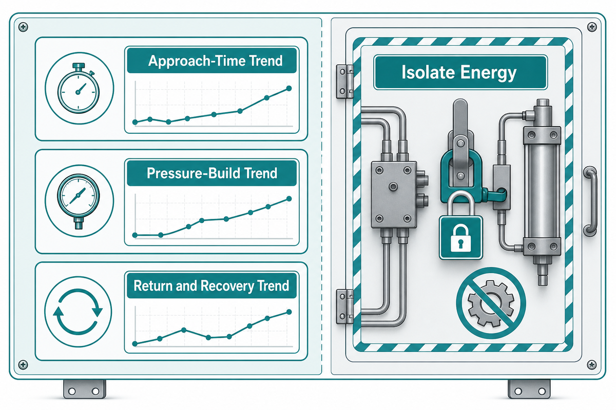
Maintenance should preserve a comparable record of the machine, not just a list of replaced parts. Trend approach time, pressure-build time, return/recovery time, visible leakage, unusual sound, rod and guide condition, air-treatment status, local pressure behavior and the accepted workpiece result. Note tool, material, recipe and utility changes beside each entry.
Gradual drift and a step change suggest different investigations. Drift may justify checking contamination, leakage, restrictions, alignment or temperature against the known-good baseline. Step changes immediately after tooling, maintenance or control work should keep that event visible in the record. Neither pattern proves a part failure by itself.
Service life can’t be reduced to a universal cycle number. It depends on the approved load, alignment, air and fluid condition, duty, environment, maintenance practice and model-specific limits. Use the applicable documentation and comparable machine history rather than a generic promise.
Before hands-on inspection, isolate energy and prevent unexpected motion according to the machine’s approved procedure. In the United States, OSHA 29 CFR 1910.147 addresses servicing where unexpected energization, start-up or release of stored energy could injure personnel. OSHA 29 CFR 1910.212 addresses machine guarding, including point-of-operation hazards. These are U.S. workplace references, not worldwide legal advice or component certification.
As a conservative machine-level safety boundary, stop and escalate when there’s uncontrolled movement, active oil loss, damaged structure or rod, repeated pressure excursions, missing operating limits, a changed safety function or an application outside the approved design. “No separate hydraulic power unit” must never be translated into “no stored energy.”
What to Prepare Before a BS & BT Application Review
Initiate application review with verifiable evidence. Prepare workpiece and process objective; required approach and power-stroke travel; contact tolerance; acceptable force or displacement range; tooling and load path; required cycle profile; dynamic air condition; ambient and contamination environment; mounting envelope; sensing and control; guarding envelope; and acceptance method.
Also identify which requirement is fixed and which can move. Machine builders may be able to adjust approach travel but not the installation envelope. Quality may require a recorded work result while production may be flexible on cycle time. Procurement needs those boundaries before comparing configurations, because a price comparison made on incomplete application data can place unlike solutions in the same column.
Use the eight-input RFQ readiness checker to collect the late-stage inputs. To compare the wider family before narrowing the architecture, see pneumohydraulic drive cylinders. For company and manufacturing background, visit About SIMITCH.
Start a BS & BT application discussion
Frequently Asked Questions
What does “hydropneumatic” mean in a booster cylinder?
It means pneumatic and hydraulic domains work together in one actuator. Compressed air supplies the drive energy, while a contained liquid circuit transfers intensified pressure during the short work stroke. This pairing can provide fast travel and a compact high-force phase, but the machine still has both pneumatic and hydraulic boundaries to integrate, isolate and maintain. Here, “hydropneumatic” doesn’t mean a suspension accumulator, gas compressor or conventional HPU-driven cylinder.
Is a gas-liquid booster cylinder the same as a gas booster pump?
No. A gas booster pump raises gas pressure and delivers gas flow between inlet and outlet conditions. By contrast, a gas-liquid booster cylinder produces linear travel and force for a machine operation. Their application inputs, safety boundaries and acceptance tests differ even when both descriptions use “booster,” “pressure ratio” and “air drive.”
How does a gas-liquid booster cylinder multiply force?
During the short working stroke, the booster stage uses an area-ratio effect to raise liquid-side pressure. Resulting force depends on effective pressure and piston area, while pressure drop, friction, back pressure and the machine load path reduce what reaches the workpiece. A catalogue ratio therefore describes a reference relationship, not a guaranteed process result. Check dynamic supply, contact position, alignment, tooling stiffness, frame deflection and the accepted workpiece outcome together during commissioning.
What information is needed to review a BS or BT configuration?
Prepare the workpiece result, force or displacement window, approach and work-stroke travel, contact condition, cycle profile, dynamic air supply, tooling/load path, mounting envelope, environment, sensing, controls and acceptance method. Published model details stay on the solution page.
Why can the power stroke feel weak when the regulator looks normal?
Regulator pressure may look normal at rest while available pressure or flow changes during approach or intensification. Contact transition may also occur at the wrong position, the load path may flex, tooling may bind, or the process demand may have changed. Compare dynamic point-of-use pressure, position, control state and workpiece result on the same timeline before naming the cause or changing a setting.
What should be recorded during commissioning?
Record dynamic pressure, contact position, control state, work displacement, accepted result, return time and recovery. Keep instrument location and workpiece identity with the trace.
A Better Decision Starts With the Whole Cycle
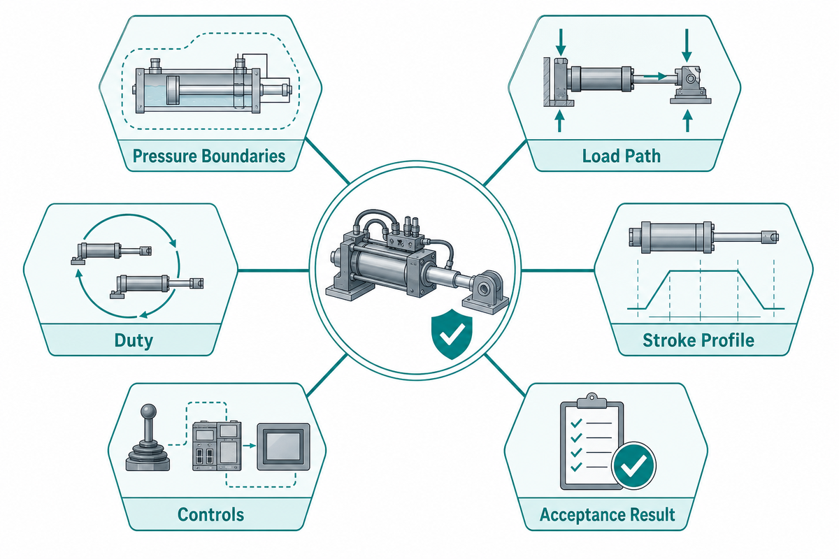
Gas-liquid booster cylinders make sense when their fast approach and short intensified work stroke match the real machine task. Catalogue data starts the conversation; it doesn’t finish the engineering. Define the pressure boundaries, load path, stroke profile, duty, controls and acceptance result, then prove them together during commissioning.
That method also protects maintenance decisions. Known-good cycles show whether a later change begins in supply, travel, transition, pressure build, tooling or recovery. When the application is ready for published specifications and configuration review, return to the Gas-Liquid Booster Cylinders, BS & BT Series solution page.
Discuss your application with SIMITCH
References & Sources
- U.S. Department of Energy: Compressed Air Systems
- ISO 4413: Hydraulic fluid power, General rules and safety requirements
- ISO 4414: Pneumatic fluid power, General rules and safety requirements
- OSHA 29 CFR 1910.147: The control of hazardous energy
- OSHA 29 CFR 1910.212: General requirements for all machines



WHY WE WRITE THIS
About SIMITCH
SIMITCH develops sheet-metal joining equipment for clinching, riveting, servo pressing, pneumohydraulic drive and hot-melt connection applications. Our engineering team starts with the material stack, access envelope, cycle target and acceptance method before recommending a machine route.
Founded in 2006 in Taicang, Jiangsu, SIMITCH combines research and development, in-house production and global sales. These guides turn field experience into practical decision support for process engineers, plant teams and industrial buyers.
OUR EXPERIENCE
Since 2006
Equipment engineering, machining, assembly and joint validation under one manufacturing system.
OUR EXPERTISE
Five joining routes
Clinching, riveting, SPR, precision press-fit and hot-melt connection for production lines.