Get in touch with Suzhou Simitch Machinery Co., Ltd Company

Pneumohydraulic Drive Cylinders: Commissioning, Diagnostics & Maintenance Guide


Pneumohydraulic drive cylinders are best diagnosed as a timed cycle, not as a single force number. In a typical arrangement, compressed air moves the actuator quickly, an intensified oil circuit supplies the short working stroke, and the system then returns and recovers for the next cycle. When a machine is slow, weak, or inconsistent, record inlet pressure, valve and sensor state, position, and process output on the same timeline. That separates an approach problem from a power-stroke or return problem. This guide covers commissioning and diagnostic evidence; product configuration, pressure-conditioned force data, and quotation inputs remain on the SIMITCH commercial Page.
Documentation language is not always consistent. One manual may call the approach actuator a pneumatic cylinder and the intensified section a hydraulic cylinder; another may group the arrangement with air-over-oil cylinders. Terms such as double-acting, tie rod, bore size, and cylinder chamber describe construction or sizing, not a fault diagnosis. Use the installed drawing and parts list to identify what each term means before comparing traces.
Read the cycle before changing a setting

The broad label “slow cylinder” hides the evidence needed to correct a problem. Start by dividing the cycle into three observable phases. The exact sequence, limits, and terminology must come from the operating manual for the installed drive and machine, but the following view gives a practical way to organize a trace.
Phase A: pneumatic approach
During approach, look for smooth linear motion, a repeatable trigger or contact position, stable pressure close to the actuator, and no sign that the tool or guide is binding. That idle regulator reading is only one reference point. It does not show the pressure and flow available at the actuator while the valve is open and the mechanism is moving. U.S. Department of Energy compressed-air guidance likewise treats point-of-use losses and system pressure stability as system questions, not merely a setpoint question.
Phase B: hydraulic power stroke
After contact or the defined transition point, the useful record is a short, controlled displacement together with the commanded valve state, pressure rise, and resulting process output. Depending on the process, output may be a measured displacement, an accepted formed feature, a joining check, or another documented quality criterion. Pneumohydraulic designs commonly reserve their high-force phase for this short portion of the cycle rather than applying peak force across the entire travel; manufacturer technical overviews describe that pneumatic-approach and intensified-power-stroke sequence. Do not turn that general architecture into a substitute for the installed unit’s force, stroke, or pressure limits.
Phase C: return and recovery
Return is not just the visible retract. Confirm the completed end position, return time, and enough recovery time for the next cycle at the actual duty condition. A machine can appear to return normally at low frequency yet become inconsistent when the sequence repeats. Separating return and recovery from approach time prevents a common mistake: changing a flow control or regulator because the whole cycle “feels slow” before the slow phase has been measured.
Practical timeline: use one clock for position, local inlet pressure, valve command, sensor state, and process result. A simple trace with five aligned channels is more useful than five isolated observations. It lets the team ask whether the pressure drop preceded the late transition, whether the transition preceded the poor result, or whether the result changed while the motion trace remained stable.
Request an engineering discussion about the recorded cycle
Capture a known-good commissioning baseline
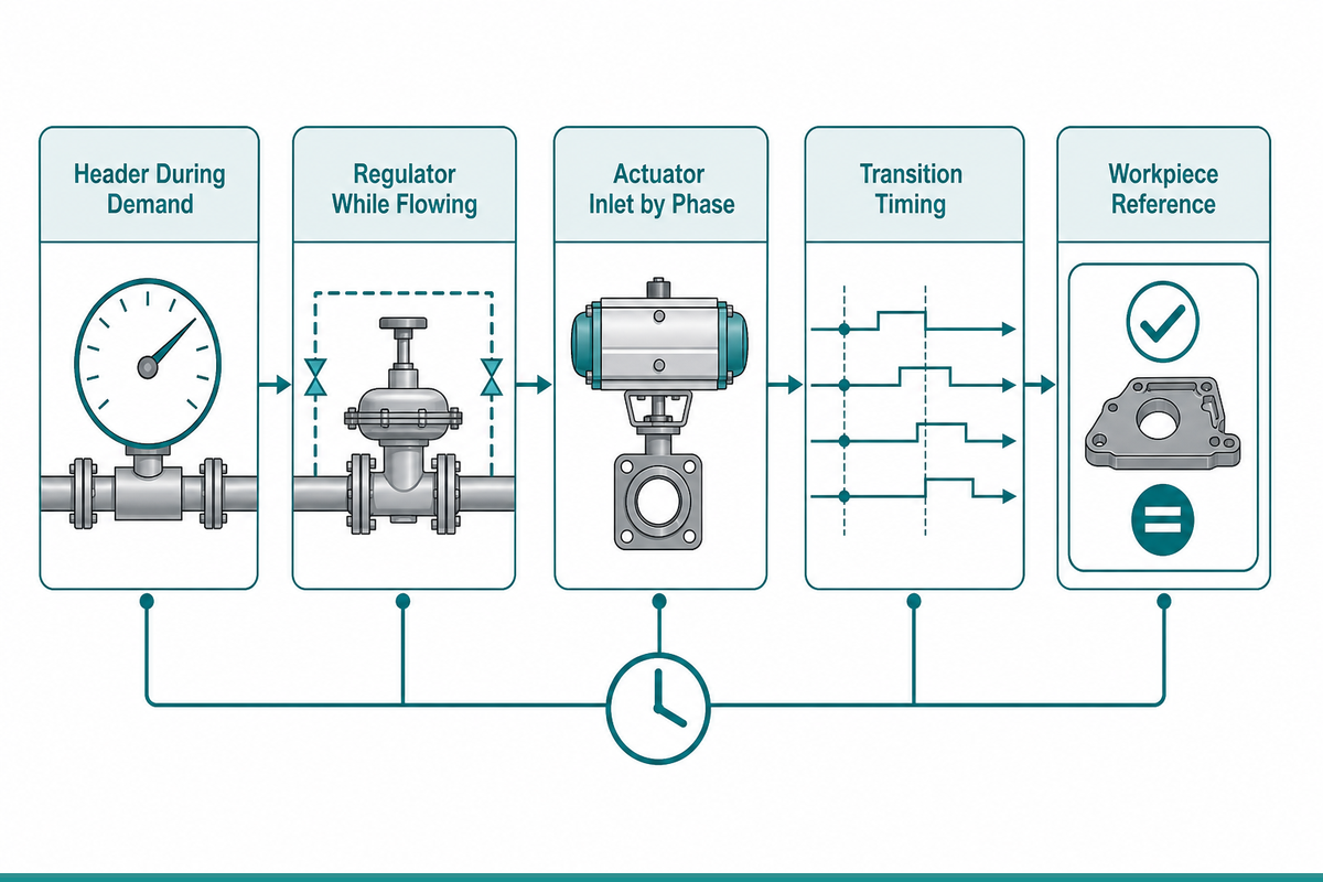
Commissioning is the point at which later troubleshooting becomes easier or much harder. The goal is not to create a universal acceptance sheet. It is to preserve a trustworthy reference for one installed machine, one measurement boundary, and one declared workpiece condition.
Establish safe preconditions
Before making or touching a measurement, verify the machine’s isolation procedure, guarding, point-of-operation controls, and the limits in the applicable drive and machine manuals. Check the condition of the tool, workpiece, fixtures, and external guides used for the reference cycle. ISO 4414 provides general rules and safety requirements for pneumatic fluid-power systems on machinery; it does not certify a completed machine or select its application-specific safeguards. Follow the responsible machine builder’s risk assessment and lockout procedure before any hands-on inspection.
Record the minimum data set
- Plant header pressure during demand, not only at rest.
- Machine regulator outlet pressure at rest and while flowing.
- Pressure near the actuator inlet during approach, power stroke, and return.
- Approach time and the contact or trigger position.
- Power-stroke time, dwell if used, and the resulting workpiece check.
- Return time, completed end position, and recovery before the next cycle.
- Valve and sensor states at each transition.
- Instrument location, units, range, sampling interval, and the workpiece reference.
The first 30 cycles can be used as an editorial commissioning framework: first verify a dry or otherwise safe cycle, then retain the first workpiece cycle, then compare it with a stable warm condition. The number is not a manufacturer requirement. Its value is that it stops a team from calling a single favorable observation a baseline. If the instrument moves to the other side of a valve, if the workpiece changes, or if the sampling method changes, create a new reference rather than comparing unlike readings.
“Known good” should mean that the measurement boundary is known as well. A pressure value without its location and timing cannot reliably explain a cycle.
Troubleshoot six symptoms with evidence
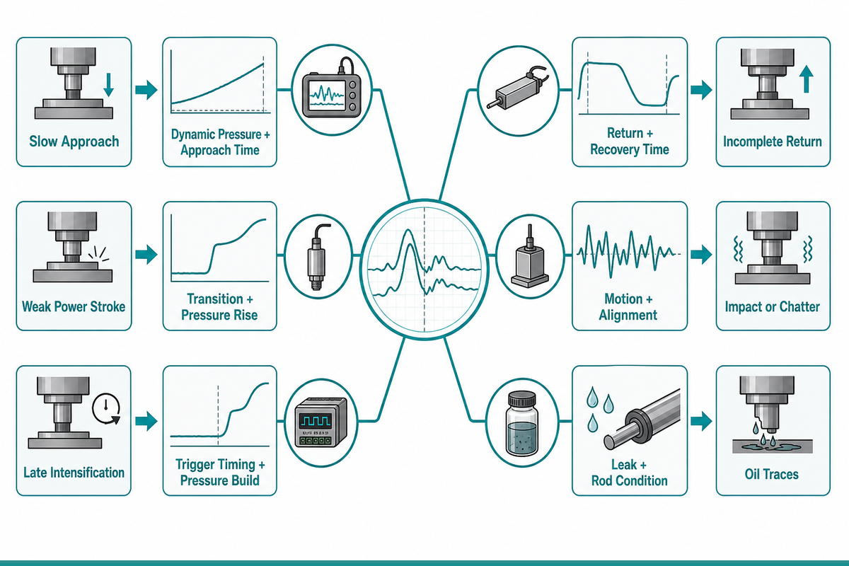
The matrix below is an editorial diagnostic framework synthesized from manufacturer service guidance and compressed-air system guidance. It is not a fault-code list and it is not a parts-replacement instruction. Use the applicable manual to decide what measurements, pressures, service procedures, and escalation paths are permitted for the installed model.
| Observed symptom | Evidence to capture first | Subsystem to examine | Safe next step |
|---|---|---|---|
| Slow approach | Dynamic pressure at the actuator, approach time, valve command, and contact position | Local supply restriction, valve behavior, exhaust path, hose routing, or external binding | Compare the local trace with the known-good baseline before changing a setting. |
| Normal approach, weak power stroke | Transition position, intensification command, pressure rise, and process output | Sequence, supply under flow, tooling demand, or permitted operating boundary | Verify the manual limit and application demand; do not increase pressure to hide an unknown cause. |
| Delayed or inconsistent intensification | Valve command, sensor transition, piston position, and pressure rise on one clock | Trigger logic, sensor placement, valve response, or mechanical contact point | Determine whether triggering is late or pressure build is slow before changing sequence logic. |
| Slow or incomplete return | Completed end position, return time, recovery time, and return-side pressure behavior | Tool weight, guidance, flow or exhaust restriction, refill/recovery, or end-position sensing | Record the forward-to-return speed relationship and inspect only under the approved service procedure. |
| Impact, chatter, or unstable end position | Motion trace, trigger location, alignment check, end-stop condition, and valve timing | Tooling alignment, side load, damping rule, or sequence timing | Stop if uncontrolled motion is possible; have the responsible engineer review alignment and control logic. |
| Oil traces or repeated seal damage | Leak location, cycle count, rod condition, air quality condition, contamination, and speed behavior | Service condition, supply quality, corrosion/dirt exposure, loading, or model-specific seal system | Stop active leakage or uncertain safety conditions and use the manufacturer’s service route. |
For example, a normal static gauge does not rule out a local pressure drop during approach. Conversely, a stable actuator-inlet pressure does not prove that a late sensor transition or mechanical contact point is correct. The measurement tells you which branch of the investigation deserves attention; it does not prove a single root cause by itself.
Check external guidance and side load
Manufacturer service guidance warns against treating a piston rod as a radial guide. External tooling and guidance should carry side load. If an alignment problem is suspected, observe the relationship among the tool, workpiece, guide elements, and cylinder centerline under the approved inspection method. Do not use the rod or the actuator body as the place to “prove” a fixture correction by forcing the mechanism into position.
Once the measurement-led diagnostic framework is clear, use the commercial Page to compare SIMITCH pneumohydraulic drive cylinder configurations. It owns family selection, pressure-conditioned force data, and quotation inputs; this guide deliberately does not duplicate them.
Use a five-point measurement chain
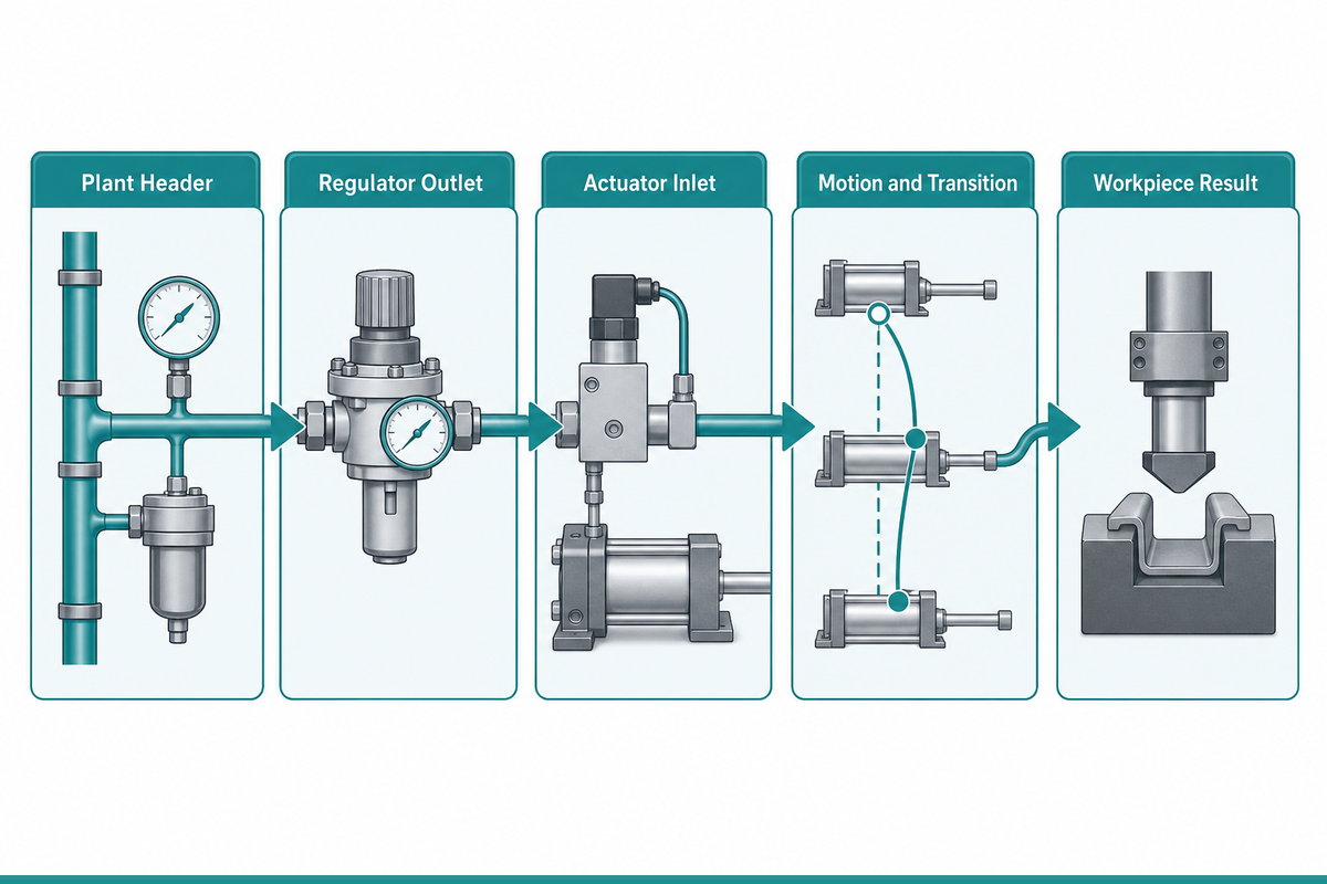
When a trace does not match the baseline, measure from the utility source to the process result. This chain creates a shared language between maintenance, controls, tooling, and process engineering:
- Plant header: what pressure is available to the machine during demand?
- Regulator outlet: what changes across the machine’s local control boundary?
- Actuator inlet: what reaches the drive while the relevant valve is flowing?
- Motion and transition: where are the approach, contact, intensification, and return events?
- Workpiece result: did the declared quality or displacement outcome change with the trace?
Interpret patterns conditionally. A stable header combined with falling actuator-inlet pressure points toward a local restriction or demand issue worth investigating. A pressure trace that stays stable while the transition arrives late points more directly toward sensing, sequencing, or mechanical contact. A correct transition with poor output calls for verification of the intensification sequence and application demand within the manual’s limits. If output remains repeatable while total cycle time drifts, separate approach, power, return, and recovery before naming the cause.
Instrument discipline matters. Note gauge or transducer range, location, units, and sampling interval. Readings on opposite sides of a valve are not interchangeable, and a low-rate display may miss a short event that a time-synchronized data trace would show. The U.S. Department of Energy’s compressed-air resources are useful context for considering point-of-use pressure and system losses, but the installed machine manual remains the controlling source for the actuator.
Share a trace or symptom record with the engineering team
Maintain the evidence, not just the hardware
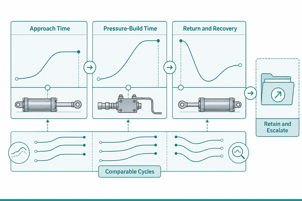
Service intervals are more useful when they preserve what changed. Per shift or at the interval defined by the responsible manual, record visible oil traces, rod condition, unusual sound, end-position behavior, fitting and hose condition, and pressure behavior during demand. Check air-treatment and filter status against the installed system’s requirements. Manufacturer service material identifies issues such as dirt, corrosion-related conditions, speed-ratio changes, and undersized supply components in its own product context; do not generalize those causes to every drive without inspection and the relevant manual.
Trend three clocks: approach time, power-stroke or pressure-build time, and return/recovery time. A change in one clock can be a prompt for measurement before it becomes a stoppage. It is not, by itself, a directive to replace a valve, alter a hose, or adjust pressure. Preserve the workpiece, tool condition, utility condition, and measurement boundary with each entry so later comparisons remain meaningful.
Review the trend after a declared number of comparable production cycles, rather than reacting to a single outlier. A useful entry distinguishes a gradual drift from a step change after a tool, recipe, utility, or maintenance event. It also records whether the workpiece result changed with the timing change. That distinction keeps a maintenance record from becoming a list of unconnected alarms. If the record shows a repeatable deviation but no safe local explanation, retain the trace and escalate it with the machine history instead of repeatedly resetting the baseline.
Service life is not a universal cycle count. Treat it as an outcome influenced by the approved load, alignment, air quality, duty, maintenance practice, and the specific manufacturer’s limits, then use comparable trend records to show whether those conditions are changing.
For company background and the stated machining, assembly, and testing context behind its clinching and precision-pressing equipment, see about SIMITCH. That information does not replace the model-specific maintenance documentation supplied for a particular machine.
Recognize an application mismatch
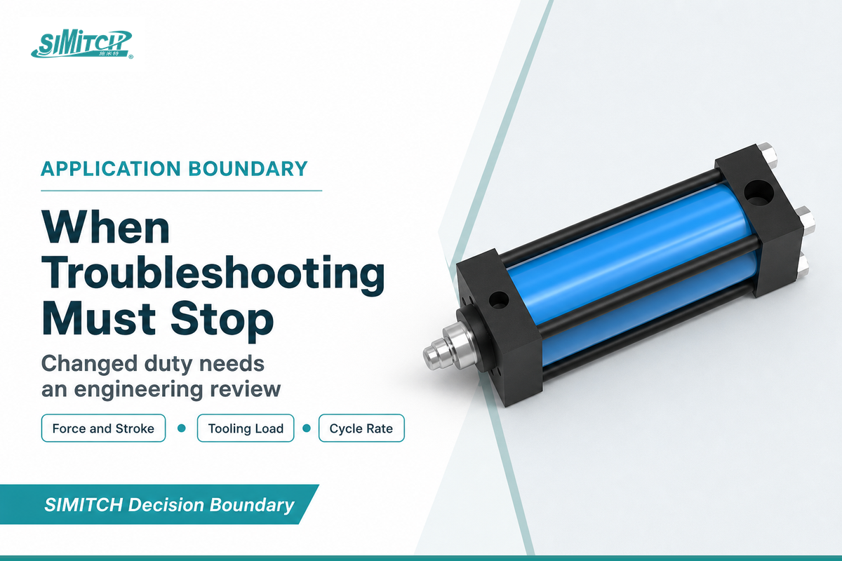
Not every recurring symptom is a maintenance defect. Troubleshooting cannot restore a requirement that has moved outside the approved application. Pause the adjustment cycle and ask an engineering question when the duty has changed.
In industrial automation, a compact design or a higher automation level can change the required drive system, but neither explains an existing symptom on its own. The same applies when industrial applications move toward hydraulic or electric motion: first document what changed in force, motion, return stroke, utilities, and evidence requirements.
| New requirement | Why troubleshooting may not solve it | Engineering question |
|---|---|---|
| Required force or power-stroke length changed | The prior drive may be operating within its former task but outside the new one. | What process requirement changed, and what operating limits apply? |
| Tool mass, eccentricity, or side load increased | External guidance and the drive’s approved loading boundary may no longer match the tooling. | Which component carries radial load, and has alignment been revalidated? |
| Cycle rate increased | Pressure recovery and the full motion sequence may be inadequate at the new duty. | What do the approach, power, and recovery traces show at production rate? |
| Motion profile or traceability requirement changed | A different control or drive architecture may be needed rather than another local adjustment. | Which force, position, timing, and record requirements are now mandatory? |
If the issue is genuinely an architecture decision rather than a fault investigation, a servo, pneumatic or hydraulic press comparison can help frame the decision. Use it only after the required motion, force, traceability, utilities, installation envelope, and duty have been documented. It should not be used to bypass a safety review or to choose a replacement from a symptom alone.
Apply a clear safety and escalation boundary
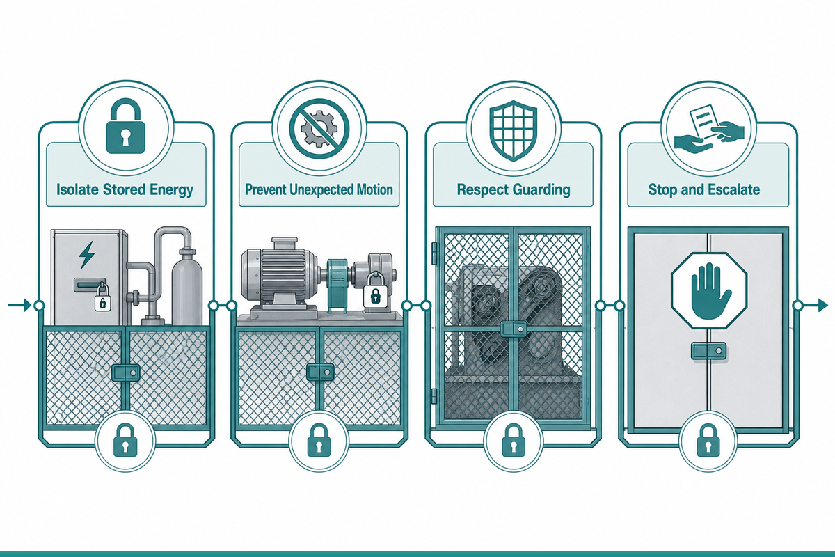
Isolate pneumatic energy and any stored hydraulic energy before hands-on work, prevent unexpected motion, and respect guarding and point-of-operation controls. Stop and involve the responsible engineer, machine builder, or manufacturer when there is uncontrolled movement, visible structural or rod damage, active oil loss, repeated pressure excursions, missing operating-manual limits, a changed safety function, or an application change outside the approved design. These are decision boundaries, not a suggestion to keep testing until a pattern appears.
The ISO description of ISO 4414:2010 is a useful safety framework for pneumatic systems and components on machinery. It cannot determine the safety functions of a finished machine. Local legal requirements, the machine risk assessment, and the applicable model manual remain in force.
Send an engineering handoff that can be used
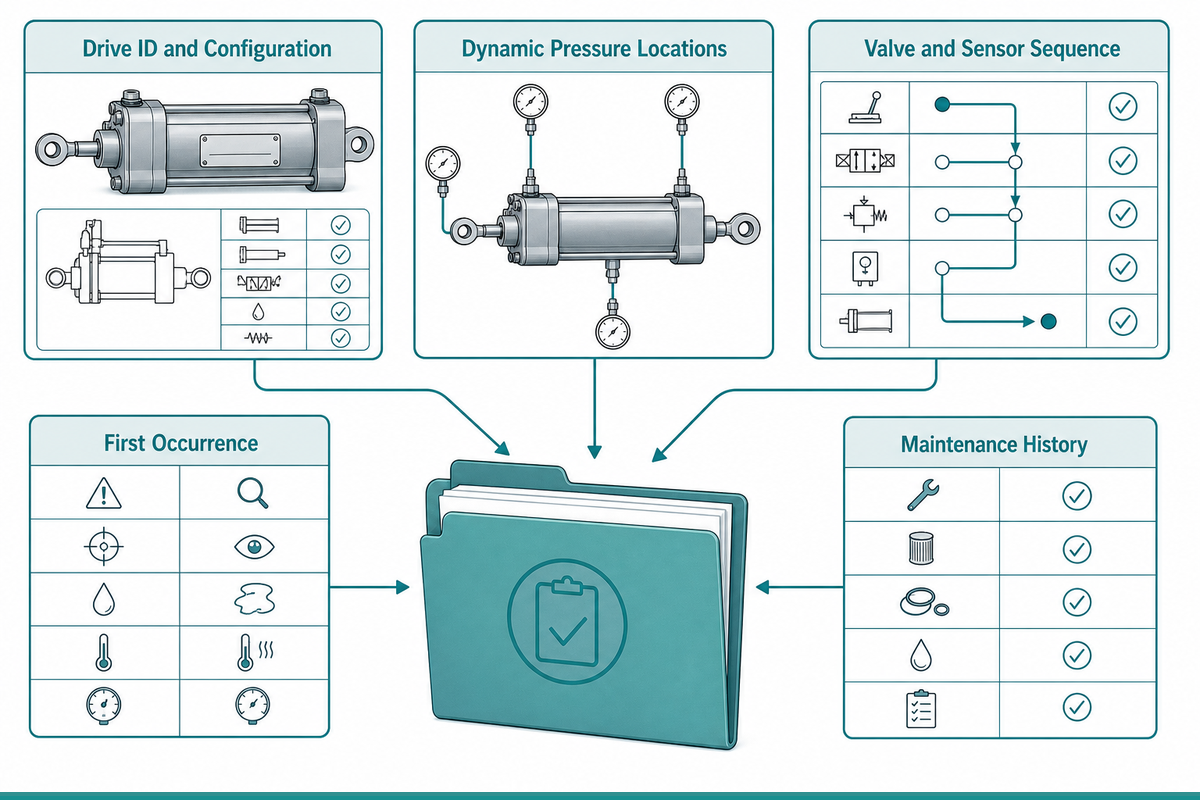
An effective handoff gives the next engineer a reproducible condition, rather than an unqualified description of a weak or slow cylinder. Include the drive identification and current configuration; workpiece and tool history; required process output; approach, power, and return timing; dynamic pressure readings with instrument locations; valve and sensor sequence; symptom photos or video where permitted; the first occurrence; and maintenance or parts-replacement history. State what changed just before the issue appeared, including utilities, tooling, recipe, cycle rate, or measurement method.
Discuss the documented application and cycle evidence
Frequently asked questions
Why can the power stroke be weak when the regulator looks normal?
The regulator may be normal at rest while local pressure and flow differ during the relevant phase. Compare dynamic actuator-inlet pressure, valve and trigger sequence, transition position, and process output. Also verify that the application demand remains within the installed drive’s documented operating boundary. Do not make a blind pressure increase as a diagnostic method.
What makes a pneumohydraulic cylinder cycle slowly?
Measure approach, pressure build, dwell if used, return, and recovery separately. A restriction, sequence delay, mechanical binding, or recovery limitation can produce similar total cycle times while requiring different corrective paths. The trace should direct the investigation.
Can side load damage the cylinder?
Side load can create a condition that the piston rod was not intended to guide. Use external tooling guidance, verify alignment, and follow the product manual. Record where the load enters the tooling, whether the guide elements carry it, and whether the symptom changes with a declared workpiece or fixture condition. If there is visible damage or uncontrolled movement, stop and escalate instead of attempting an in-cycle correction.
How should cycle time be measured?
Use repeatable timestamps for approach, transition, power, return, and recovery under a declared workpiece and utility condition. Record the instrument location and sampling method with each trace so that a later comparison remains valid. If production rate matters, repeat the trace across enough comparable cycles to expose recovery drift; do not mix warm-up, maintenance, or changed workpiece conditions into the same baseline.
When is another drive architecture worth reviewing?
Review the architecture when force or stroke needs, motion profile, traceability, utilities, duty, tooling load, or installation/service constraints have changed beyond the approved application. First document the new requirement; then keep product configuration and quotation discussions separate from fault finding.
Conclusion
Pneumohydraulic drive cylinders become easier to commission and maintain when the team diagnoses synchronized evidence rather than isolated gauge readings. Establish a known-good baseline, keep the pressure, position, sequence, and workpiece result on one timeline, and use the model manual as the limit for every adjustment or service action. When the evidence indicates a changed application rather than a repairable fault, stop troubleshooting and take the documented requirements to the appropriate engineering review.
Start an engineering conversation
References & Sources
- SIMITCH pneumohydraulic drive cylinders commercial page — scope boundary and three-phase-cycle orientation.
- TOX pneumohydraulic drive overview — general pneumatic approach and intensified working-stroke context.
- TOX service FAQ — manufacturer-specific service observations, treated here as bounded diagnostic context.
- U.S. Department of Energy compressed-air systems resources — point-of-use pressure and system-performance context.
- U.S. Department of Energy Better Plants compressed-air resources — reliability and maintenance system context.
- ISO 4414:2010 — pneumatic-system safety framework and scope.



WHY WE WRITE THIS
About SIMITCH
SIMITCH develops sheet-metal joining equipment for clinching, riveting, servo pressing, pneumohydraulic drive and hot-melt connection applications. Our engineering team starts with the material stack, access envelope, cycle target and acceptance method before recommending a machine route.
Founded in 2006 in Taicang, Jiangsu, SIMITCH combines research and development, in-house production and global sales. These guides turn field experience into practical decision support for process engineers, plant teams and industrial buyers.
OUR EXPERIENCE
Since 2006
Equipment engineering, machining, assembly and joint validation under one manufacturing system.
OUR EXPERTISE
Five joining routes
Clinching, riveting, SPR, precision press-fit and hot-melt connection for production lines.