Get in touch with Suzhou Simitch Machinery Co., Ltd Company

What Is a Blind Rivet? How It Sets From One Side and Where It Fits

When engineers ask what is a blind rivet, it’s typically given as a two piece tubular permanent mechanical fastener that’s installed from one accessible side. More widely known as a pop rivet, it comprises a headed hollow cylindrical shell and an internal solid mandrel with a breakneck notch. In the process of removing the stem, the hollow tail of the blind rivet clamps down to a bulb in the hidden back side and breaks off at a predetermined load.
The major benefit of blind rivets is that these rivets are designed for one-sided assembly where the rear face is blocked. Unlike solid rivets that need access to both sides, an installer on the front face, upsets the tail end and completes the rivet. This engineering reference provides one-sided assembly, mechanical settings, eight styles of blind rivet bodies, drill hole tolerances, ISO strength standards, and automated riveting tools.
How Does a Blind Rivet Work? Rivet Body, Mandrel Breakneck Mechanics, and Pop Rivets and Blind Rivets
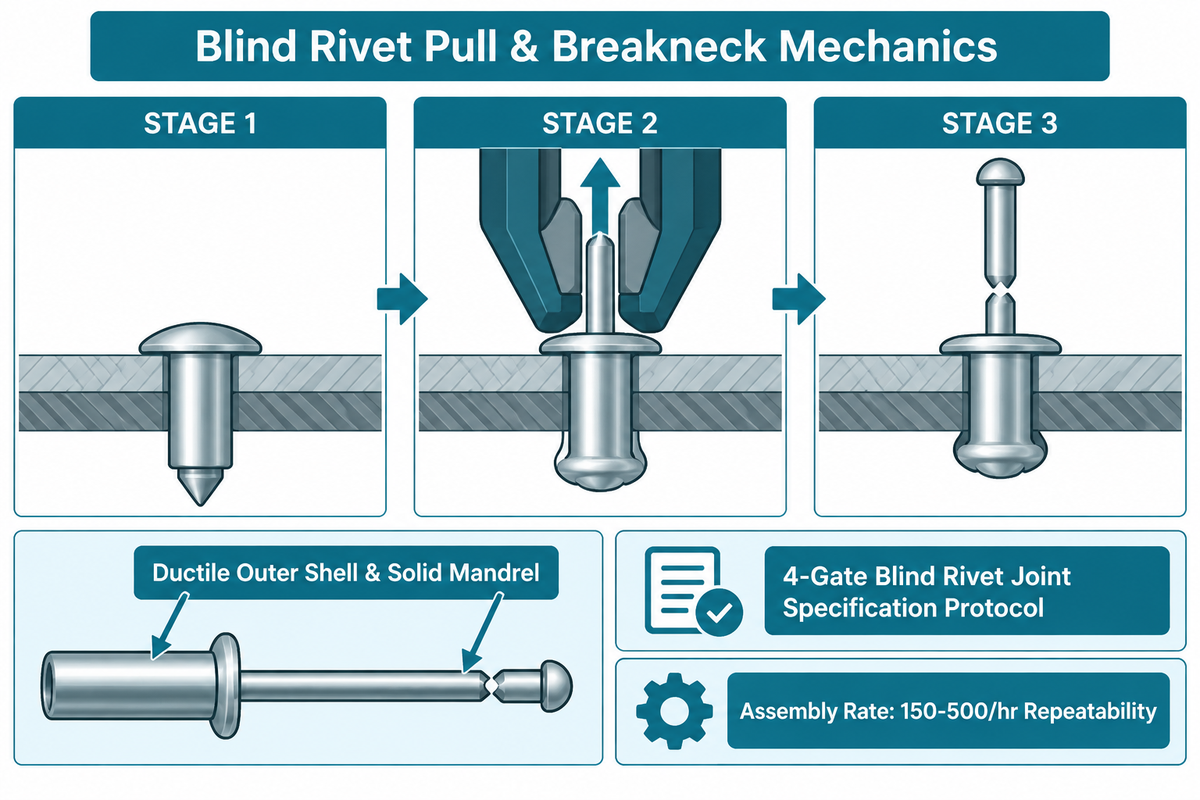
A blind rivet is a type of axial pulling connection that converts tension into radial expansion and blind-side compression of a hollow sleeve. According to the NASA Fastener Design Manual (NASA-RP-1228) and Assembly Magazine’s engineering handbook on blind riveting, break-stem blind rivets rely on a ductile outer shell and a higher-tensile mandrel. As Machine Design’s engineering report on blind rivets states, they can be set at a rate of 150-500/hr with identical repeatability.
Each pre-assembled unit consists of two precision metal components and is as follows:
- Hollow Tubular Shell (Sleeve): A metal tube with a preformed flange at the accessible end. The outer diameter of the rivet is put through a drilled hole in the materials being joined.
- Solid Internal Mandrel (Stem): A high-strength wire pin running through the center bore of the rivet body.
During a single pull stroke, a blind rivet joint forms in four stages as follows:
- In the first stage, the user guides the shell through aligned holes until the preformed rivet head rests against the front sheet. A tool nosepiece acts as a stationary anvil.
- Blind-Side Bulb Initiation: In the second stage, a tool consists of collet jaws that grip the tail of the mandrel, and pull it backwards. As the mandrel is pulled, the stem head creates a bulb in the sleeve.
- Draw Together and Fill Holes: As the expanding bulb reaches the back sheet, further axial force draws the sheets together. At the same time, the bulb’s shank expands to contact the wall of the hole.
- Predetermined Breakneck Fracture: As the blind bulb seats against the back sheet, the tensile stress concentration occurs at the breakneck notch. The stem of the blind bulb fractures cleanly, and the sleeve of the bulb is locked in the back sheet.
For a comparative analysis of single side cold upsetting vs. double side forming, see Industrial riveting Process Mechanics and Joint Design with respect to solid, semi-tubular and blind fastening systems, where a high level of shear strength is required.
The 4-Gate Blind Rivet Joint Specification Protocol
Our 4-Gate Blind Rivet Joint Specification Protocol screens joints across four consecutive engineering gates prior to procurement.
- Gate 1 (Access and Cavity Gate): Determine if the joint is a through-hole with a back sheet cavity or a dead end hole. Use blind rivets for through-holes and rivets for dead-end cavities.
- Gate 2 (Retention and Sealing Gate): Decide if the shear plane requires an integrated stem, sealed cup or wide petals.
- Gate 3 (Bimetallic Anodic and ISO Load Gate): Match the sleeve alloy to the parent sheet to block galvanic attack. Verify single-shear and tensile breaking loads against ISO 15977, EN ISO 15979, or ISO 15983 tables.
- Gate 4 (Grip Envelope and Tooling Gate): Sum the layer thicknesses to pick the right grip range and drill bit size. Match shift volume to manual pliers, air-hydraulic guns, or bowl-fed auto-feed pulling heads.
Are Pop Rivets and Blind Rivets the Same Thing?
Yes, in workshop practice, pop rivets and blind rivets refer to the same two-piece break-stem fastener installed from one side. Technically, “blind rivet” is the generic term across ISO standards, while “POP” is a brand name owned by STANLEY Engineered Fastening. As the MIT D-Lab Fasteners engineering guide and Fastenere’s technical overview state, the authentic POP® rivets are blind rivets, while a lot of factories make ISO blind rivets as different branded products.
What Type of Blind Rivet Fits Your Joint? Open End, Sealed Blind Rivets, Structural, and Multi-Grip Blind Rivets
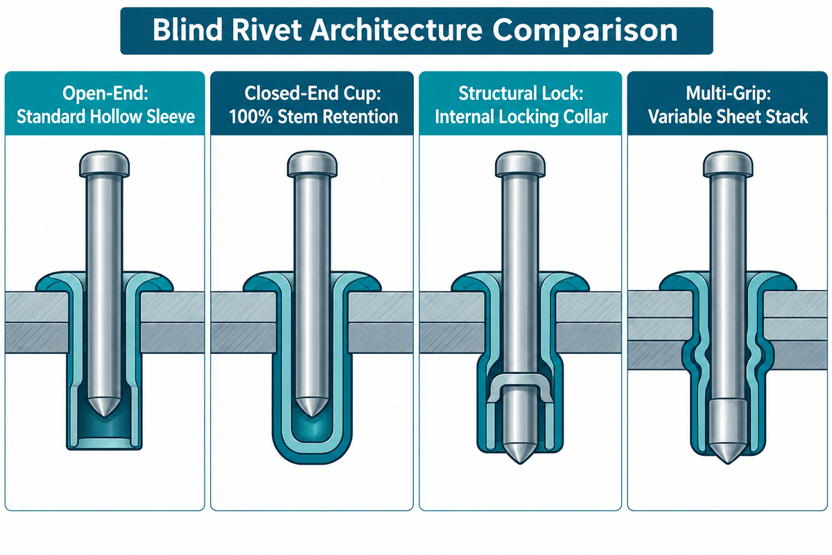
Choosing a type of blind rivet or specialized type of rivet depends on joint shear, fluid sealing, vibration, stack tolerance, and substrate hardness. As noted in Essentra Components’ application guide, standard open-end sleeves work with light guards but fail with heavy vibrating frames or soft plastics. In STANLEY Engineered Fastening’s technical catalog, closed-end and multi-grip designs (closed-end cups providing 100% stem retention) provide reliable stem retention to prevent electrical shorts and rattling.
Compare the eight primary blind rivet types, their blind-side deformation mechanics, and their application limits in the table below:
| Row | Blind Rivet Type | Blind-Side Deformation and Stem Retention | Shear Plane Cross-Section | Sealing Capability | Primary Industrial Applications and Limits |
|---|---|---|---|---|---|
| 1 | Standard Open-End Break-Stem (ISO 15977 / EN ISO 15979) | Hollow tail flares into a single round bulb; residual stem plug held only by friction | Hollow tubular wall only (stem not counted in structural shear) | Unsealed center bore; loose stem plug can vibrate out | General sheet metal guards, HVAC ducts, light brackets; avoid in high vibration or live electrical cabinets |
| 2 | Closed-End / Sealed Cup (ISO 15976 / ISO 16585) | Solid cup-shaped blind end expands radially; stem head stays trapped inside closed cup | Hollow tubular wall across joint line; zero FOD stem loss | Complete internal bore seal against water, vapor, and dust | Marine decks, outdoor enclosures, fuel tanks, electronics chassis; requires smooth hole and sealant for outer rim sealing |
| 3 | Structural Mechanically Locked Interlock (Magna-Lok / Monobolt / US4012984A) | Tail expands to fill hole tightly while an internal locking collar locks the solid pin | Solid steel or alloy pin locked inside expanded sleeve across shear plane | Weather-resistant plug seal; high clamp and fatigue life | Commercial truck trailers, solar trackers, bus and rail frames, heavy machinery; requires high-traction installation tool |
| 4 | Multi-Grip Blind Rivets | Stepped sleeve walls fold into multiple stacked bulbs with 100% stem retention | Thickened folded tubular wall with captured stem head | Weather-resistant stem lock; dampens sheet rattle | Assemblies with variable sheet thickness tolerances; one multi-grip SKU replaces several standard grip sizes |
| 5 | Tri-Fold / Bulb-Tite Splitting Rivets | Slotted tubular body splits and folds into three wide load-spreading legs on the blind face | Tubular shank with wide three-leg blind-side bearing footprint | Optional under-head elastomer washer for roofing weather seal | Thin aluminum sheet, blow-molded plastics, composite panels, automotive interior trim; prevents rear pull-through |
| 6 | Peel / Split-Petal Blind Rivets | Sharp mandrel head slices the aluminum shell into four curling petals that grip soft material | Low-shear tubular neck with four wide clamping petals | Unsealed open core | Upholstery, plywood, drywall, urethanes, fiberglass insulation boards; not for structural metal shear |
| 7 | Grooved Blind Hole Rivets | Annular external serrations expand radially against the interior wall of a dead-end cavity | Friction-locked serrated cylinder inside base material | Unsealed center bore | Attaching metal nameplates, hinges, or brackets into non-through blind holes in hardwood, thick plastic, brick, or concrete |
| 8 | Drive-Pin (Hammer-Set) Blind Rivets | Protruding center pin is struck flush with a hammer, splaying split tail prongs outward | Solid center pin wedged inside split tubular prongs | Unsealed split tail | Field masonry signage, architectural channels, and blind holes where no pulling gun is available |
Is a Blind Rivet the Same as a Sealed Rivet or a Structural Huck Rivet?
No; a sealed rivet and a structural Huck rivet are high-performance subsets within or adjacent to the blind rivet family. In a standard open end blind rivet, the hollow body is open at both ends, so fluids pass through the center bore. By contrast, sealed blind rivets (closed-end rivets under ISO 15976 and ISO 16585) use a drawn cup that traps the mandrel head completely. However, as Yuke Rivet’s waterproofing engineering analysis explains, a closed-end body does not automatically make the entire joint waterproof. Water can still seep between the outer sleeve and a rough drilled hole unless you add an under-flange gasket or sealant. By contrast, structural Huck lockbolts and mechanically locked Magna-Lok or Monobolt fasteners cold-lock an internal collar or stem into the sleeve to resist severe structural shear and vibration where standard hollow open-end bodies would loosen.
A “Huck rivet” refers either to a one-sided structural blind rivet (such as Huck Magna-Lok) or a two-sided swaged lockbolt. As disclosed in US Patent US4012984A (Blind rivet assembly with locking collar), a structural blind rivet swages an internal locking collar into a groove on the solid stem before breakneck fracture. That mechanical lock keeps the solid pin inside the shear plane for heavy dynamic loads.
Head Styles, Drilled Hole Tolerances, and Grip Range Sizing for Standard Blind Rivets and Blind Hole Rivets
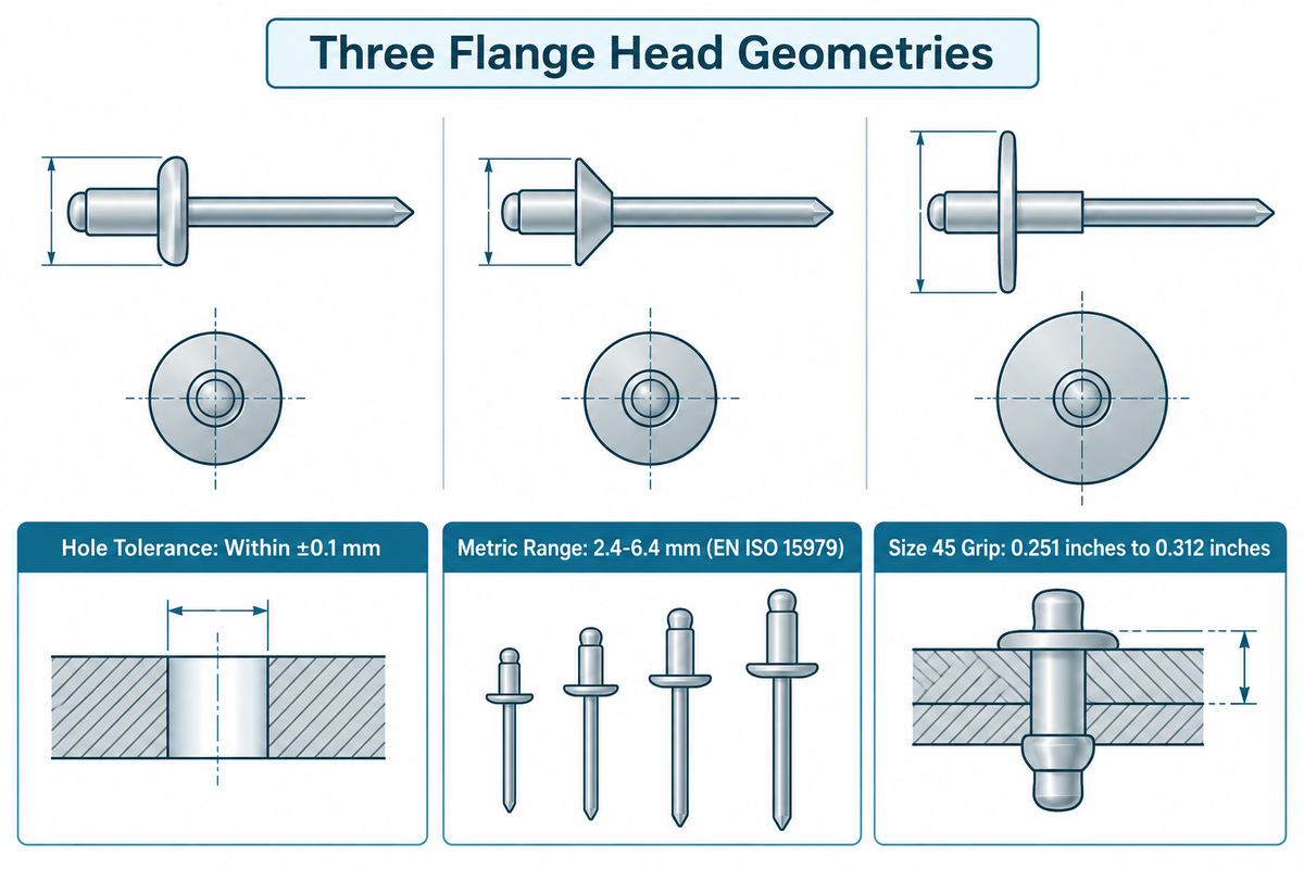
Choosing the appropriate head style, hole clearance, and grip range prevents flange pull-through, buckled tails, and loose sheets. According to Bolt Depot’s blind rivet sizing guide and Machine Design’s joint specification rules, standard blind rivets come in three flange geometries.
- Dome Head (Protruding Head): The standard low-profile rounded flange covered by ISO 15977, EN ISO 15979, and ISO 15983. It is suitable for most steel and aluminum sheets.
- Countersunk Head (Flush Head): Features a flat top face and a beveled underside standardized under ISO 15978, ISO 15980, and ISO 15984. A precision countersink gives the head a flat surface that is in contact with an aerodynamic skin or sliding surface.
- Large Flange Head: Broadens the outer flange to spread the clamping pressure over a large area. This gives adequate bearing area to prevent thin, soft, and brittle materials from pulling over the head.
What Size Drill Bit Should You Use for Blind Rivets and How Do You Measure Grip Range?
Per STANLEY Engineered Fastening’s installation rules, hole diameter must match the rivet specification within ±0.1 mm. An undersized hole restricts insertion, while an oversized hole reduces load transfer and causes loose rivets. As Machine Design notes, inch blind rivets are available in diameters from 3/32 to ¼-in., with 1/32-in. incremental increases, while EN ISO 15979 covers metric nominal diameters of 2.4–6.4 mm.
In Bolt Depot’s trade size system, the first digit of the size gives the diameter of the rivet in 32nds of an inch, while the second digit gives the maximum grip range in 16ths of an inch. For example, a size 45 rivet is 4/32″ (1/8″) diameter with a 5/16″ maximum grip range, covering a 0.251 inches to 0.312 inches grip window. Always distinguish shell length from grip range. The total thickness of the sheets should be less than the grip window and the rivet should be chosen in such a way that the grip range brackets the total thickness.
| Trade Size Prefix | Nominal Body Diameter (Inch / Metric) | Hole Tolerance Rule | Example Trade Size & Max Grip | Applicable ISO Protruding-Head Standards | Typical Sheet Metal Application |
|---|---|---|---|---|---|
| #3 (3/32 in) | 3/32 in / 2.4 mm | Match spec within ±0.1 mm | Size 32 to 36 (in 16ths of an inch grip) | ISO 15977 (AlA/St), EN ISO 15979 (St/St), ISO 15983 (A2/A2) | Light electronics brackets, thin gauge guards, small nameplates |
| #4 (1/8 in) | 4/32″ (1/8″) / 3.2 mm | Match spec within ±0.1 mm | Size 45: 5/16″ max grip (0.251 inches to 0.312 inches) | ISO 15977, EN ISO 15979, ISO 15983 | HVAC ductwork, electrical cabinets, appliance panels |
| #5 (5/32 in) | 5/32 in / 4 mm | Match spec within ±0.1 mm | 4 mm nominal diameter (EN ISO 15979 Table 3) | ISO 15977, EN ISO 15979, ISO 15983 | Medium sheet metal enclosures, machinery guards, lighting housings |
| #6 (3/16 in) | 3/16 in / 4.8 mm | Match spec within ±0.1 mm | Size 64 to 68 general structural sheet stack | ISO 15977, EN ISO 15979, ISO 15983 | Trailer body skins, racking brackets, elevator panels |
| Metric 5.0 / 6.0 | 5.0 mm to 6.0 mm | Match spec within ±0.1 mm | ISO metric standard grip intervals | EN ISO 15979, ISO 15983, ISO 16582 (Cu), ISO 16584 (NiCu) | Heavy industrial cabinets, marine and chemical equipment |
| #8 (1/4 in) | ¼-in. / 6.4 mm | Match spec within ±0.1 mm | Upper boundary of 2.4–6.4 mm ISO series | EN ISO 15979, Structural Magna-Lok and Monobolt series | High-shear truck frames, solar trackers, structural steel subframes |
Blind Rivet Materials, ISO 15977 / ISO 15983 Shear and Tensile Strength, and Aluminum Blind Galvanic Rules
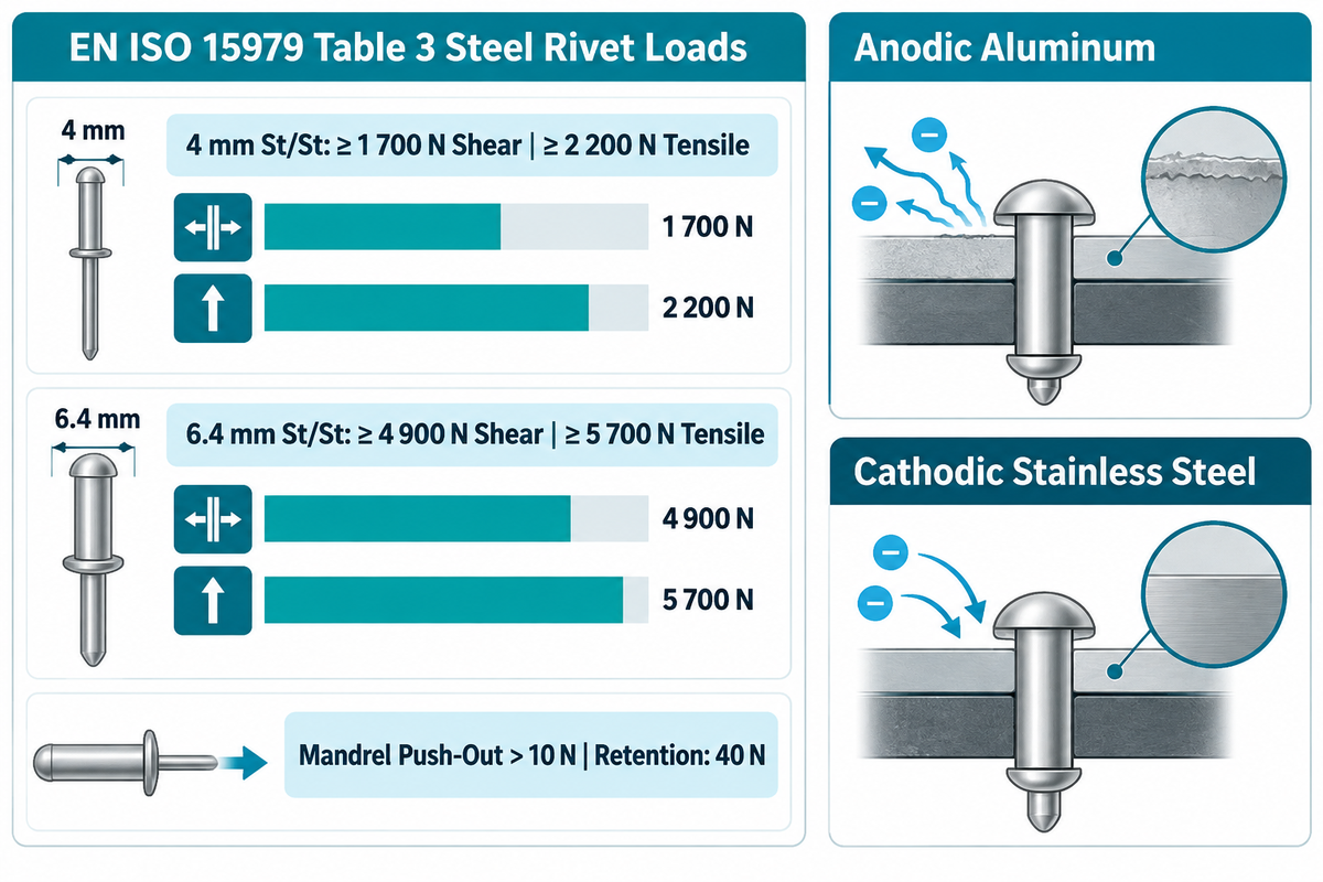
The mechanical load capacity of a blind rivet depends on its sleeve alloy, nominal diameter, and mandrel retention under ISO 14589 testing. In the EN ISO 15979:2002 / SIST EN ISO 15979:2003 standard and ISO 15983:2002 specification, each material pairing and head style is governed by a specific ISO document across nominal diameters of 2.4–6.4 mm.
For a 4 mm protruding-head steel body and steel mandrel (St/St) open-end blind rivet under EN ISO 15979 Table 3, minimum shear load is ≥ 1 700 N and minimum tensile load is ≥ 2 200 N (and for a 6.4 mm nominal diameter, minimum shear load is ≥ 4 900 N and minimum tensile load is ≥ 5 700 N). In addition, the load to push out the mandrel prior to setting must exceed 10 N, and mandrel head retention is tested at 40 N for 4 mm diameter. The electroplated zinc coating requires a minimum 5 µm thickness (Fe/Zn5c2C) with no cracking at 5× magnification. Compare the major ISO blind rivet material standards below:
| ISO Standard Number | Head & Body Style | Body / Mandrel Material Code | Diameter Scope & Verified Test Benchmark (ISO 14589) | Galvanic Corrosion & Service Environment Rule |
|---|---|---|---|---|
| ISO 15977 / ISO 15978 | Open-end protruding (15977) or countersunk (15978) | Aluminium alloy body / Steel mandrel (AIA/St) | 2.4–6.4 mm series; lightweight general sheet fastening | Matches aluminum blind assemblies indoors; coat or seal exposed steel stem stub in wet air |
| EN ISO 15979:2002 / ISO 15980:2002 | Open-end protruding (15979) or countersunk (15980) | Steel body / Steel mandrel (St/St) | 2.4–6.4 mm; for d = 4 mm: shear ≥ 1 700 N, tensile ≥ 2 200 N; for d = 6.4 mm: shear ≥ 4 900 N, tensile ≥ 5 700 N | Zinc plated minimum 5 µm (Fe/Zn5c2C); ideal for carbon steel cabinets and brackets |
| ISO 15983:2002 / ISO 15984:2002 | Open-end protruding (15983) or countersunk (15984) | Austenitic stainless body / Stainless mandrel (A2/A2) | 2.4–6.4 mm; high shear and tensile strength with zero internal stem galvanic couple | Food machinery, outdoor enclosures, stainless panels, and marine aluminum joints |
| ISO 16582:2002 / ISO 16583:2002 | Open-end protruding (16582) or countersunk (16583) | Copper body / Steel, Bronze, or Stainless mandrel (Cu/St, Cu/Br, Cu/SSt) | 2.4–6.4 mm; electrical earthing and copper roofing joints | Use only on copper or brass parent sheets; never install in aluminum sheets |
| ISO 16584:2002 | Open-end protruding head | Nickel-copper alloy (Monel) body / Steel or Stainless mandrel (NiCu/St, NiCu/SSt) | 2.4–6.4 mm; high strength corrosion and temperature resistance | Marine hulls, chemical process ducts, and aerospace secondary structures |
| ISO 15975:2002 | Closed-end sealed protruding head | Commercially pure or alloy aluminium body / Steel mandrel (AI/AIA) | Sealed cup traps mandrel head; blocks water and vapor through center bore | Watertight aluminum enclosures, ductwork, and transport containers |
| ISO 15976:2002 | Closed-end sealed protruding head | Steel body / Steel mandrel (St/St) | Sealed carbon steel cup with complete stem containment | Sealed steel electrical cabinets where loose mandrel plugs are prohibited |
| ISO 16585:2002 | Closed-end sealed protruding head | Austenitic stainless steel body / Stainless mandrel (A2/SSt) | Sealed stainless cup combining corrosion resistance with bore sealing | Corrosive chemical, food-grade, and marine pressure enclosures |
Rivets of compatible potentials should always be joined in the bimetallic joints to avoid galvanic corrosion: the smaller fastener should be equally noble or slightly more cathodic than the larger parent sheet.
- Joining Aluminum Parent Sheets: Use aluminum alloy bodies (ISO 15977 or closed-end ISO 15975) or austenitic stainless steel (ISO 15983 A2/A2). Copper and uncoated carbon steel rivets pit surrounding aluminum and should not be used.
- When joining stainless steel or copper sheets, aluminum should never be used, as the anodic aluminum rivet body is rapidly dissolved by the stainless steel in the presence of moisture.
When Should Engineers Choose a Blind Pop Fastener Over a Solid Rivet, Rivet Nut, or Self-Piercing Rivet (SPR)?
Engineers use a blind pop fastener when access from the rear is blocked, the joint is permanent, and the holes are pre-drilled or punched. However, structural engineers on Eng-Tips and fabricators on Practical Machinist point out that an open-end pop rivet is just one of the five options for joining sheet metal. Selecting an unlocked open-end rivet for a removable service panel or a high-fatigue airframe joint results in extra expense and effort for unnecessary rework.
As Atlas Copco’s engineering analysis of self-piercing rivet joints illustrates, in automotive lines with a two-sided C-frame access, the use of self-piercing riveting (SPR) for no-hole sheet joining totally eliminates the need for pre-drilled holes. Let’s compare the five joining methods.
| Fastening Process | Tool Access Required | Pre-Drilled Hole Required? | Joint Permanence | Fatigue & Shear Capacity | Best Production Fit |
|---|---|---|---|---|---|
| Open / Closed-End Blind Rivet | One-sided (blind access) | Yes (hole matched within ±0.1 mm) | Permanent (must drill off flange to remove) | Low to Moderate (hollow tubular shell in shear) | Box sections, enclosures, HVAC ducts, general sheet metal assembly |
| Structural Interlock Blind Rivet | One-sided (blind access) | Yes (hole-filling expansion sleeve) | Permanent (mechanically locked solid pin) | High (solid locked stem across shear plane) | Heavy trailers, rail cars, solar trackers, closed tubular chassis frames |
| Solid Rivet (Bucked or Orbital Formed) | Two-sided (head support + bucking bar or peening die) | Yes (shank swells to fill hole completely) | Permanent | Very High (cold-worked solid forged grain structure) | Primary aerospace airframes, precision pivot hinges, safety linkages |
| Blind Rivet Nut (Rivnut / Threaded Insert) | One-sided (threaded pull mandrel tool) | Yes (hole in single host sheet) | Permanent insert body + removable mating screw | High thread pullout; allows repeated service access | Thin enclosures, roof racks, and tubular frames needing removable bolted covers |
| Self-Piercing Rivet (SPR) | Two-sided (C-frame punch and bottom upsetting die) | No (semi-tubular rivet pierces top sheet directly) | Permanent (flared skirt interlocks in bottom sheet) | Very High dynamic peel and shear; sealed bottom sheet | High-volume automotive aluminum and steel panels, battery enclosures |
Where Blind Rivets Can Be Installed: Industrial Sheet Metal, Enclosures, Automotive, and Blind End Cavities
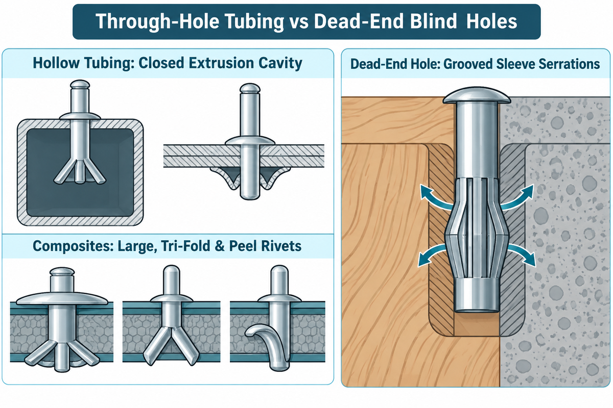
Blind rivets can be installed in any rigid or semi-rigid material stack where a drill or a punch can make a hole, and access from the rear is available for the tail. Cold setting causes no heat affected zone, thus blind rivets join painted, galvanized, anodized and dissimilar sheets without burning the coatings.
Blind rivets have five main areas of application in industrial manufacturing:
- Extruded and Framed Hollow Structures: blind rivets can be used for the mounting of brackets to square steel tubing, roll cages and aluminum solar torque tubes, where the closed cavity of the extrusion blocks the access of nuts.
- Electrical and HVAC Ductwork: blind rivets can be used for the sealing of duct seams, backplanes of control cabinets, and appliance wrappers, compare press-in and clinched methods in our guide to sheet metal fastening methods for thin enclosures.
- Commercial Vehicles, Trailers, and Bus Bodies: blind rivets can be used for structural interlock for the attachment of aluminum sheet skins to steel frame ribs in the presence of road vibration.
- Fiberglass, Plastics, and Composite Panels: Large, tri-fold, and peel blind rivets can be used for clamping in plastics, composite and fiberglass panels, where the clamping load is concentrated at the edge of the hole and can cause cracking.
- Dead-end blind holes (non-through holes) require special methods to access the cavity. If the blind hole is in wood, thick plastic, brick, or masonry, a blind rivet with a grooved sleeve can be used. JC Fasteners provides specifications of these blind rivets and show how the serrations expand outward into the cavity.
Installing a Rivet Step by Step: Hole Preparation, Rivet Gun Nosepiece Alignment, and Common Defect Fixes
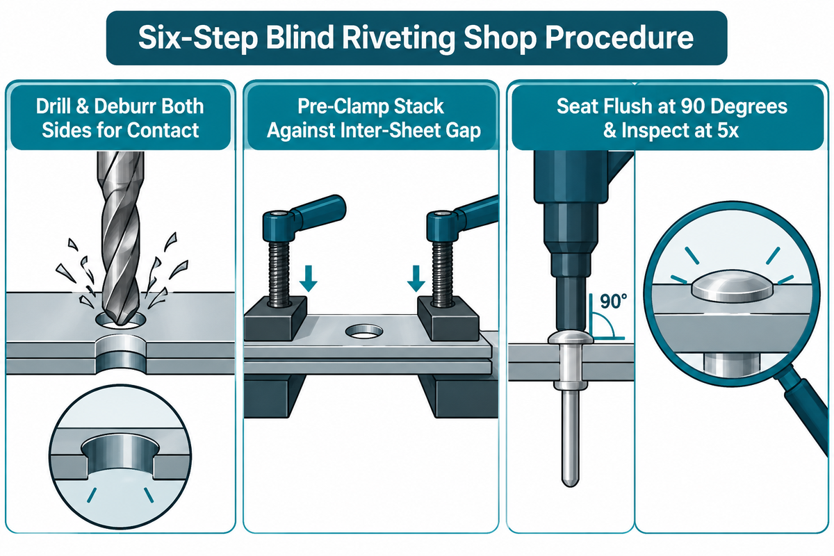
Installing a rivet is reliable, but requires a clear understanding of the hole size to ensure it’s within the allowable clearances, burrs are removed, and the tool is held perpendicular to the surface. Blind rivets are designed so they should be used to clamp together sheets that are already close together, not to pull wide gaps shut. Bolt Depot’s installation guide and Assembly Magazine’s blind riveting handbook cover these methods in greater detail.
Follow this six-step shop procedure for consistent blind riveting:
- Drill and Deburr to Specification: Drill or punch the aligned sheets to within specified hole diameter tolerance. Deburr both sides to remove burrs and allow the sheets to make full contact.
- Pre-Clamp the Material Stack: Tightly clamp the workpieces near a hole or insert alignment pins. Pre-clamping will keep the sleeve from expanding into an inter-sheet gap.
- Match the Nosepiece Bore to the Mandrel: Mount the tool with the appropriate sized nosepiece for the mandrel diameter. A nosepiece that’s too large allows the stem to flop over and dent the flange.
- Insert and Seat Flush at 90 Degrees: Insert the mandrel into the tool jaws, and the rivet body into the drilled hole, and hold the nosepiece flat against the flange.
- Actuate the Draw Stroke Until Breakneck Snap: Pull the draw pin or squeeze the handles smoothly until the stem contacts the breakneck flange. Keep the mandrel fully seated during the stroke.
- Inspect the Set Head and Spent Stems: Inspect the set flange for gaps and cracks, using 5x magnification. Empty the spent mandrel collet regularly.
When troubleshooting production defects, check these four root causes:
- Loose Rivet or Inter-Sheet Metal Flash: Occurs when the selected grip range is too long. Other causes include skipping pre-clamping or drilling an oversized hole.
- Premature Mandrel Break with Weak Clamping: The stem breaks at the flange before it contacts the hole. The cause is selecting a grip range that’s too short.
- Blind Tail Pull-Through: Most often occurs as a result of using soft, thin-walled backing materials, or from drilling an over-sized hole. To fix, switch to a large flange tri-fold, or use a multi-grip rivet with a back-up washer.
- Tool Jaws Slipping on the Mandrel: This is most often caused by metal shavings embedded in the collet jaws or low shop air pressure. Replace the jaws on schedule.
Rivet Tools and Installation Tool Scaling: Manual Hand Pliers, Pneumatic Guns, and Auto-Feed Riveting Systems

Matching the installation tool to rivet diameter, mandrel break load, and shift volume prevents operator fatigue and incomplete setting. As noted in Lematec’s air-hydraulic vs. manual riveter guide and Assembly Magazine’s production tooling report, large steel and stainless break-stem blind rivets require a high axial load, which is above comfortable single-hand plier squeezing.
Which Tool Is Used to Install Blind Rivets and Can You Set Them Without a Rivet Gun?
A dedicated break-stem blind rivet gun (manual hand pliers, two-handed lever riveter, air-hydraulic riveter, or battery powered riveter) is used for setting blind rivets. All of these tools feature a front nosepiece which braces against the blind rivet flange, and internal collet jaws which pull the mandrel. Break-stem blind rivets can’t be set using ordinary pliers, as the mandrel would simply pull out of the flange, along with the unformed rivet. If a rivet gun isn’t available, a drive-pin blind rivet can be used. The center pin is set flush and can be hammered home.
According to Machine Design, handheld tools typically install fasteners with break loads of 1,000 lb or less. However, Lematec states that, for rare field jobs without shop air, an air-hydraulic riveter isn’t always the right first purchase. Compare the four main categories of rivet tools and industrial riveting equipment and automated joining machines:
- Manual Single-Hand and Two-Handed Lever Pliers: For field repairs and prototypes with short cycles and low volume, and small rivets made of aluminum in that lower break load limit.
- Hydro-Pneumatic (Air-Hydraulic) Rivet Guns: Air-over-oil cylinders multiply shop air pressure to shear 4 mm to 6.4 mm steel, stainless, and structural stems in one trigger pull with vacuum stem collection.
- CORDLESS BRUSHLESS BATTERY Rivet GUNS:
Electric ball-screw pullers get rid of the air hose in the vehicle cabins, solar fields, and clean rooms. These pullers return stroke to adjustable positions.
- BOWL-FED BLOW-FEED AUTOMATIC RIVETING SYSTEMS:
A vibratory feeder bowl orients bulk blind rivets and blows them through a feed tube into the tool nose jaws after each cycle.
High-Volume Production Joining: From Handheld Blind Rivet Types to Automated SPR and Servo Riveting Workstations

When daily volume of production rises, manufacturing engineers assess if it’s more efficient to automate blind rivet feeding or switch to no-hole or solid-forming stations. In lines where structural rivets are also deployed, cycle time is wasted by manual drilling of holes, deburring, alignment of holes, and loading of a blind rivet one by one.
Modern automated stations also replaced manual spot-checks with real time curve monitoring. As disclosed in US Patent US7331205B2 (Rivet monitoring system), sensors on the setting tool track force and displacement during mandrel draw stroke. If a breakneck fracture happens outside the calibrated displacement window, the controller indicates it as a defect.
Three rules of engineering apply when upgrading from hand-held blind rivet guns to automated join workstations.
- AUTOMATE ONE SIDED BLIND RIVETING AND CURVE MONITORING: When closed box beams allow one side access, use a blow-feed pulling head which integrates vacuum stem extraction and force-displacement monitoring.
- Upgrade Two-Sided Solid or Semi-Tubular Pin Joints to Servo Orbital Riveting: If both sides of a hinge or bracket are accessible, replace two-piece blind rivets with solid or semi-tubular pins. Using servo riveting assembly systems with force-displacement control to form them lowers fastener piece cost and keeps head height precise.
- Upgrade High-Volume Two-Sided Sheet Stacks to Self-Piercing Riveting (SPR): In cases of joining aluminum or multi-material sheets with two-sided C-frame clearance, use automated self-piercing riveting (SPR) machines. Self-piercing riveting (SPR) eliminates pre-drilled holes, cleaning up chips and aligning holes. SPR yields a sealed bottom sheet.
FAQ
What is the difference between a blind rivet and a regular solid rivet?
A blind rivet is a two-piece tubular fastener installed from one side by pulling an internal mandrel, whereas a solid rivet is a one-piece pin requiring two-sided access.
A solid rivet is used with a braced head and a formed tail on the opposite side in primary structures of aircraft where fatigue life and structural load transfer are an issue. A solid rivet fills the hole completely, whereas blind rivets solve assembly into closed tubes, boxes, and sheet metal enclosures when the backside isn’t accessible.
Are blind rivets waterproof and airtight?
Standard open-end blind rivets are not waterproof because a hollow hole runs through the center, whereas closed-end sealed blind rivets trap the mandrel head inside a solid cup.
While a closed-end blind rivet (such as ISO 15975, ISO 15976, or ISO 16585) completely blocks water, fuel, and air from leaking through the internal mandrel bore, it does not automatically seal the outer hole perimeter. To make the entire joint watertight and airtight under pressure, pair the closed-end rivet with a smooth drilled hole and an under-flange elastomer sealing washer or sealant.
What is the difference between a blind rivet and a blind rivet nut?
A blind rivet permanently clamps two or more sheets together, whereas a blind rivet nut (rivnut) is an internally threaded tubular insert that creates reusable machine threads from one side.
A threaded pull mandrel captures a blind rivet nut during installation. During this process, the collar of the blind rivet nut is forced inward creating a bulge. The tool spindle is then unthreaded from the insert, leaving behind a metric or unified thread. Metric or unified threads allow for the removal of machine screws and small bolt covers, field access covers and brackets.
How do you remove a blind rivet without damaging the sheet metal?
Drill only through the outer flange crown using an installation-size drill bit, then punch out the sleeve.
Avoid oversized bits that enlarge the parent sheet hole.
Why does the mandrel rattle or fall out of an open-end blind rivet?
In a standard non-structural open-end blind rivet, the broken mandrel head is held only by sleeve friction without a positive mechanical locking ring.
Under EN ISO 15979 testing, mandrel head retention in a 4 mm open-end steel rivet is verified at a modest 40 N test load. When the drilled hole is oversized or the sheet stack sits near the top of the grip range, sleeve grip weakens. Under continuous vibration, the residual stem plug can shake loose, rattle inside the bore, or drop out as conductive foreign object debris inside control cabinets. Switching to multi-grip rivets with 100% stem retention, closed-end sealed cup rivets, or mechanically locked structural interlock rivets eliminates stem rattle completely.
What hole tolerance and inspection rules apply to EN ISO 15979 blind rivets?
Holes must stay within tolerance, mandrel push-out resistance must exceed 10 N, and set heads cannot crack at 5× magnification.
Loose holes reduce shear load transfer.
Can aluminum blind rivets be used to join stainless steel or copper sheets?
No; aluminum blind rivets must not be used to join stainless steel, Monel, or copper panels in humid, outdoor, or marine environments due to rapid galvanic corrosion.
Aluminum is strongly anodic relative to austenitic stainless steel and copper. Placing a small aluminum rivet body inside a large cathodic stainless or copper sheet creates an aggressive electrochemical cell whenever moisture bridges the joint. The small aluminum anode dissolves rapidly and fails in shear. Always match the rivet alloy to the parent metal or choose a slightly more noble fastener. Specify ISO 15983 A2/A2 stainless steel or ISO 16584 Monel blind rivets for stainless assemblies, and ISO 16582 copper blind rivets for copper parts.
References & Sources
- NASA –
NASA Reference Publication 1228: Fastener Design Manual (Richard T. Barrett, Lewis Research Center) - MIT D-Lab –
MIT D-Lab Fasteners Engineering Guide: Screws, Bolts, Nuts, Washers and Pop Rivets - STANLEY Engineered Fastening – Technical Catalog of POP Non-Structural Open-End, Closed-End, and Multi-Grip Blind Rivets
- Bolt Depot – Blind Rivet Sizing: Diameter Dash Numbers, Grip Range, and Drill Bit Chart
- Machine Design – Straight Facts on Blind Rivets: Joint Design, Edge Distance and Galvanic Corrosion
- Eng-Tips Engineering Forums – Blind Rivets vs. Solid Rivets in Structural and Vibrating Assemblies
- Practical Machinist Forum – Fastening and Threading Methods for Thin Aluminum Sheets and Enclosures
- Atlas Copco Industrial Technique – Creating a Strong and Reliable Joint with Self-Piercing Rivets (SPR)
- JC Fasteners – Rilli Grooved Blind Rivets for Non-Through Blind Holes in Wood, Plastic, and Masonry
- Lematec Pneumatic Tools – Air-Hydraulic Riveter vs. Manual Riveter: Industrial Riveting Tools
- International Organization for Standardization (ISO) ISO 15983:2002 Open-End Blind Rivets with Break Pull Mandrel and Protruding Head, A2/A2 Stainless Steel
- European Committee for Standardization / iTeh Standards EN ISO 15979: Open-End Blind Rivets with Break Pull Mandrel and Protruding Head, St/St
- Assembly Magazine Assembly Handbook: Blind Riveting Mechanics, Styles, and Joint Design
- Assembly Magazine Riveting: The Blind Side – Advances in Structural Rivets and Auto-Feed Tooling
- Yuke Rivet Are Blind Rivets Waterproof? Engineering Guide to Closed-End Sealed Rivets
- United States Patent and Trademark Office/Google Patents US4012984A: Blind Rivet Assembly with Mechanical Locking Collar
- United States Patent and Trademark Office/Google Patents US7331205B2: Blind Rivet Setting Force and Displacement Monitoring System
- Essentra Components What Are Blind Rivets Used For?
- Fastenere What Is a Blind Rivet? Anatomy, Head Styles and Sizing
- Bolt Depot Using Blind Rivets: Three-Step Installation Mechanics
Related Posts





WHY WE WRITE THIS
About SIMITCH
SIMITCH develops sheet-metal joining equipment for clinching, riveting, servo pressing, pneumohydraulic drive and hot-melt connection applications. Our engineering team starts with the material stack, access envelope, cycle target and acceptance method before recommending a machine route.
Founded in 2006 in Taicang, Jiangsu, SIMITCH combines research and development, in-house production and global sales. These guides turn field experience into practical decision support for process engineers, plant teams and industrial buyers.
OUR EXPERIENCE
Since 2006
Equipment engineering, machining, assembly and joint validation under one manufacturing system.
OUR EXPERTISE
Five joining routes
Clinching, riveting, SPR, precision press-fit and hot-melt connection for production lines.