Get in touch with Suzhou Simitch Machinery Co., Ltd Company

Types of Rivets: Structural Families, Head Styles, and How to Choose a Rivet

Standard types of rivets are permanent mechanical fasteners that join two or more parts together without threads. Different from threaded bolts that crews unbolt with wrenches, standard metal rivets feature a cylindrical shank and have a factory-formed head on one end. Setting tools upset or flare the opposite end of the rivet so the head and a tail clamp the stack. The guide contrasts elastic push-in pins and repairable outer-thread self-piercing pins with permanent rivets.
Procurement mistakes happen when fastener catalogs merge head shapes and threaded inserts in core structural families. Engineering drawings separate direct-joining fasteners in two ways: joint side access and retention mechanics. To choose the right type of rivet, one should match joint access first: one-sided holes take blind hardware while two-sided joints take solid or semi-tubular pins. Self-piercing rivets demand C-frame punch-and-die clearance and a ductile bottom sheet, and all families should match hole tolerance and galvanic compatibility.
Key Engineering Takeaways
- Separate core families from sub-specs by grouping fasteners based on installation access and retention mechanics first. Dome, flush and large flange heads should be considered as sub-specifications, and threaded blind rivet nuts should be classified separately from direct sheet-clinching rivets.
- Solid rivets fill close-tolerance holes for primary shear and fatigue duty. Semi-tubular rivets, according to Universal Rivet, have a tail hole depth of less than 112% of the shank diameter and are set at about a quarter of the force of solid rivets.
- Decouple mandrel locking from fluid sealing because an open-end blind rivet can retain its mandrel through a mechanical lock while leaving a water path through its body. Add under-head sealant or washers where watertightness is required, even on closed-end cups.
- Self-piercing and servo stations test force-displacement curves to detect missing fasteners or stack drift. Where specifications mandate destructive qualification, physical interlock is confirmed by metallographic cross sections and peel/shear tests.
What Are the Main Types of Rivets? A Two-Axis Classification
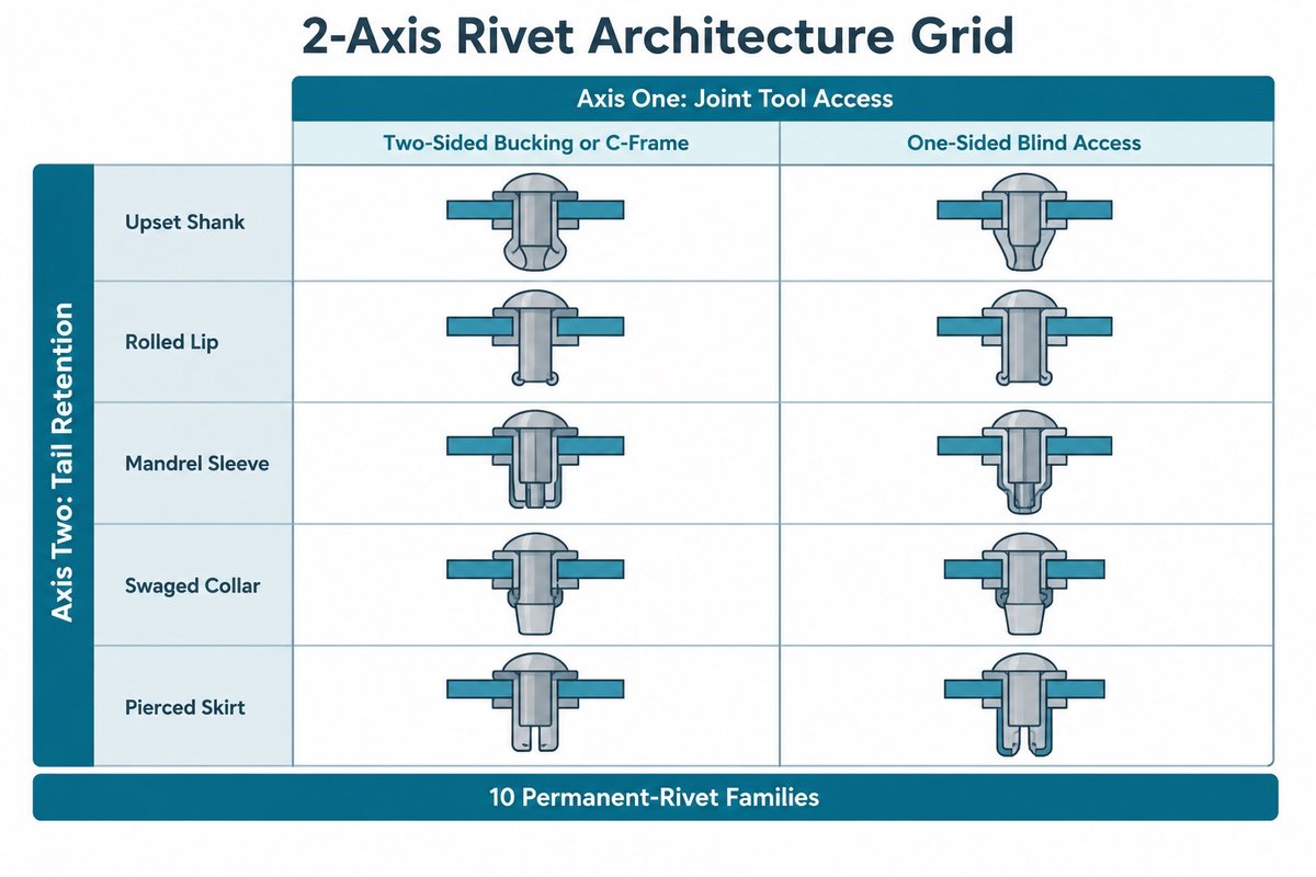
The main industrial families are solid, semi-tubular, full-tubular, open-end and closed-end blind, mechanically locked structural blind, collar-swaged lockbolt, self-piercing, drive and bifurcated split pins. Each conventional rivet is a mechanical fastener that clamps sheets without threads, so catalogs listing countersunk heads alongside solid and blind families blur head geometry with load-bearing mechanics. We organize direct-joining fasteners using the 2-Axis Rivet Architecture Grid, an editorial engineering framework rather than an industry standard.
Axis one defines tool access: two-sided bucking access, one-sided blind access, or two-sided C-frame die support. Axis two defines the retention mechanism, separating permanent metal locking achieved by deforming the rivet from elastic engagement in related push-in clips. Common metal tail mechanisms include full-shank upsetting, lip rolling, mandrel-drawn expansion, collar swaging, and self-piercing flare.
Separate internally threaded blind rivet nuts (rivnuts) from direct-joining rivets before reading the grid. The NASA RP-1228 Fastener Design Manual (Richard T. Barrett, Lewis Research Center) describes rivnut setting. A blind rivet nut does deform plastically during installation. As a result, a backside flange of the nut bulges out and grips the surrounding metal. However, a blind rivet nut doesn’t clinch sheets directly with an unthreaded shank. Instead, it provides an internal thread for a machine screw or bolt that can be removed.
How 5 Common Types of Rivets Fit Different Types of Rivets in Manufacturing
Introductory shop guides often stop at 5 common types of rivets: solid, blind, tubular, split, and drive designs. Production lines expand those basic groups into 10 distinct permanent-rivet families. This prevents misapplication of lockbolts, self-piercing hardware, and bifurcated pins. While rivets usually hold shear joints, rivets are similar only outside because internal tail mechanics govern real load capacity.
| Rivet Family | Side Access Required | Pre-Drilled Hole | Tail Locking Mechanism | Load Tier and Typical Duty |
|---|---|---|---|---|
| Solid rivet (bucked or squeezed) | Two-sided (gun/squeezer + bucking bar) | Required (close tolerance) | Full axial shank radial swell and upset tail | Primary shear and fatigue; airframes, bridge gussets, heavy brackets |
| Semi-tubular rivet | Two-sided (driver + roll-clinch anvil) | Required (clearance fit) | Shallow tail bore rolls outward at reduced axial force | Medium shear or pivot; linkages, brake linings, switchgear |
| Full-tubular rivet | Two-sided (punch + star or roll die) | Self-pierces soft goods or punched | Deep hollow cavity curls flat against backing die or washer | Light retention; leather goods, webbing, thin polymer cards |
| Open-end blind (POP) rivet | One-sided blind setting tool | Required (standard blind drill) | Pulled mandrel expands sleeve and snaps at breakneck | Light-to-medium enclosures; HVAC ducts, chassis, appliances |
| Closed-end sealed blind rivet | One-sided blind setting tool | Required (standard blind drill) | Sealed cup body traps broken mandrel head inside | Moisture-resistant enclosures; boats, gutters, sealed cabinets |
| Mechanically locked structural blind | One-sided structural nose tool | Required (tight hole tolerance) | Mechanical locking feature secures retained stem to rivet body | High shear and vibration; truck bodies, rail cars, solar racks |
| Two-piece collar-swaged lockbolt | Two-sided (pin + front swage tool) | Required (interference or clearance) | Metal collar cold-swaged into annular pin grooves | Heavy clamp preload; mining frames, trailer chassis, bridges |
| Self-piercing rivet (SPR) | Two-sided C-frame punch and die | None in standard stacks (hard-layer clearance hole in variants) | High-strength skirt pierces top sheet and flares below | High-fatigue mixed stacks; EV battery trays, body-in-white |
| Hammer-driven pin (drive) rivet | One-sided or blind pocket (hammer) | Required (through or blind hole) | Driven center pin spreads slotted prongs outward | Light mounting; nameplates, masonry anchors, liner panels |
| Split (bifurcated) rivet | Two-sided clinching access | Self-pierces suitable soft goods or prepared hole | Split legs bend outward and flatten against back face | Light retention; leather luggage, fiberboard, soft trim |
Before detailed sizing, compare different rivet types by installation access and tail-locking mechanics to avoid selecting an incompatible fastener family. Related nylon push-in clips snap elastically into prepared holes for removable service covers rather than permanent metal joints. Once you lock the structural rivet type, rivets are popular on manual benches and robotic cells alike, where rivets are also paired with a specific forming mechanism.
Solid Rivets vs. Semi-Tubular and Full-Tubular Rivets
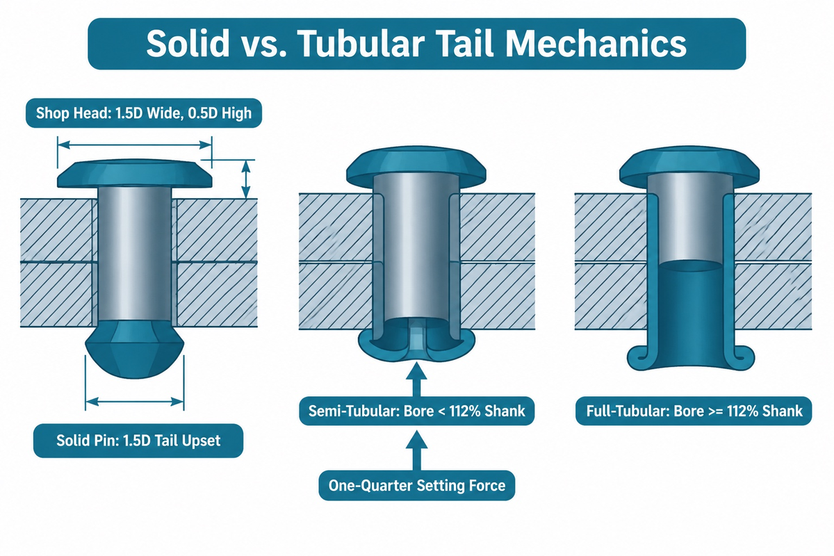
When both sides of an assembly are open, engineers consider full-section shear versus forming load. Solid rivets include round, universal, pan, and countersunk pins that swell plastically across the entire cross-section. Under forming, the solid shank of the pin expands radially and fills the bore, and a bucked “shop head” forms on the tail side.
FAA Advisory Circular AC 43.13-1B, Change 1 defines civil aviation practice, with active scope confirmed on its status page. Before upsetting, a solid pin has a protruding tail of approximately 1.5 times the shank diameter (1.5D). After upsetting, the tail reaches about 1.5D in diameter and 0.5D in height. FAA AC 43.13-1B applies only to nonpressurized civil aircraft areas lacking manufacturer repair instructions. Approved repair data for the pressurized areas of an aircraft may be provided in an OEM structural repair manual or an approved engineering repair scheme.
When should I choose a tubular rivet over a solid rivet for permanent fastening?
Choose a semi-tubular rivet over a solid rivet when high bucking force would crack brittle plastics, ceramics, or circuit boards. Use a semi-tubular rivet on a linkage joint that must pivot freely only when a controlled setting height, a shoulder, or a spacer limits clamping friction. According to Universal Rivet, semi-tubular rivets require approximately one-quarter the setting force of solid rivets.
Universal Rivet sets the limit of what’s semi-tubular and what’s full-tubular. A semi-tubular rivet has a tail hole depth that’s less than 112% of the shank diameter. The shear plane is in solid metal if the interface of the sheet falls on the unbored section of the shank. According to Universal Rivet, the minimum shear edge distance should be twice the diameter of the rivet. Full-tubular hollow rivets have a hole depth of at least 112% of shank diameter, punching cleanly through leather, fabric, or thin plastic with lower shear strength.
Orbitform’s industrial guidelines give clear stick-out rules for general manufacturing. Impact-clinched solid steel pins typically use a 100% diameter stick-out, or 3.175 mm on a 1/8-inch pin. Semi-tubular roll clinching reduces stick-out to 50% through 55% of shank diameter. Every solid or tubular rivet requires rigid backside support so the rivet in place doesn’t buckle thin panels. Review how a riveted joint forms across radial, orbital, and impact stations for full cycle mechanics. Solid pins remain commonly used in the aerospace industry where fatigue margins govern primary joints.
Blind Rivets (POP Rivets): Open-End, Closed-End, Multi-Grip, and Structural

Closed box tubes, roll-formed channels, and sealed housings obstruct anvil access behind the joint. For one-sided assemblies, blind rivets include four main sub-types: open-end break-mandrel, closed-end sealed cup, multi-grip, and mechanically locked structural designs. Though their installation guns and outward appearances are similar, they differ in vibration shear retention, behavior of stem corrosion, and weather sealing.
What type of rivet is used where access is from one side only?
Blind rivets specifically built for joints that are accessible from only one side are commonly known as POP rivets. An operator inserts the tubular rivet body into a pre-drilled hole on the face of the joint. Pulling jaws draw an internal mandrel whose head expands the blind sleeve before snapping at a breakneck.
International standards separate open-end utility hardware from sealed blind designs. ISO 15977:2002 covers open-end break-pull-mandrel blind rivets with protruding heads, aluminum-alloy bodies, and steel mandrels across nominal diameters from 2.4 mm to 6.4 mm. Standard open-end pop rivets are the most common choice for dry indoor sheet-metal enclosures. Inside the sleeve, the mandrel tip seats like a nail head during pull expansion. Without positive mechanical retention, vibration can shake the broken mandrel stub loose, and plain steel stubs can rust outdoors inside aluminum sleeves.
ISO 15973:2000 covers a specified closed-end break-pull-mandrel blind rivet design with an aluminum-alloy body and steel mandrel. Closed-end cups are used in applications where snapped stems must never fall into live electronics or tanks. Technical guides from JLCMC and HLC Metal Parts highlight a strict sealing boundary. The closed cup blocks the central leakage path, but water can still pass between the sleeve and hole wall or around the flange if those interfaces are not sealed.
Multi-grip blind sleeves accommodate variable sheet-stack thicknesses through radial deformation of the rivet body. For heavy trucks, rail cabinets, or solar trackers under severe vibration, operators install the rivet using a mechanically locked structural blind design that secures the retained stem across the shear plane. Match outdoor sleeve and stem alloys, such as stainless steel or sealed compatible pairs, to avoid wet galvanic attack. Collar-swaged lockbolts provide high preload and resist rotational loosening, but require two-sided access to insert the pin and swage the collar.
Self-Piercing Rivets (SPR), Drive Rivets, and Split Rivets
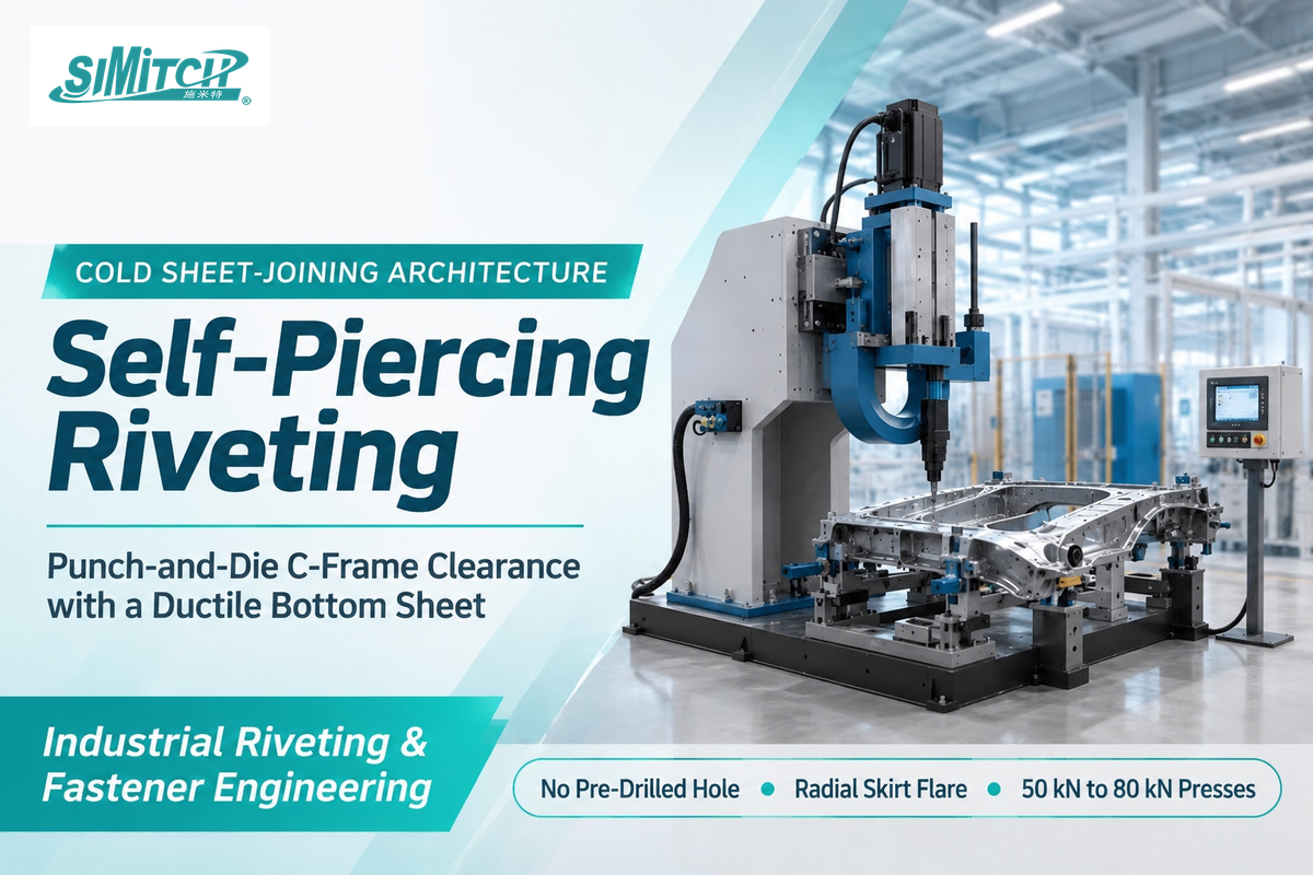
Pre-drilling and aligning holes across multi-layer stamped panels adds cycle time and tolerance drift. Conventional self-piercing rivets eliminate pre-drilling when connecting materials like coated aluminum and steel in volume production. Specialized mixed-material variants can place a clearance hole in a hard or brittle upper layer before self-piercing the ductile bottom sheet.
In TWI paper SAE 2001-01-0979, it’s described how a lightweight self-piercing tool creates this cold joint. A high-hardness fastener in a semi-tubular configuration is driven by a C frame press through the upper sheet stack. Contoured die geometry underneath flares the skirt radially inside the lower sheet without breaking through the back skin. The lower sheet is cold joined by the self-piercing process. Self-piercing riveting joins pre-painted and adhesive-bonded stacks. Piercing and deformation can locally abrade coatings and displace adhesives.
Self-piercing riveting requires punch-side and die-side C-frame throat clearance plus a ductile bottom sheet so the skirt flares without cracking the die button. Having no pre-drilled hole doesn’t mean one-sided access. For example, TWI paper SAE 2001-01-0979 specifies 64 kN steel-frame and 53 kN composite-frame design loads on 850 mm deep-throat automotive C-frames. SIMITCH publishes 50 kN and 75 kN hydro-pneumatic self-piercing riveting (SPR) machines alongside an 80 kN servo riveting assembly system, illustrating specific equipment envelopes rather than a universal SPR load range. When joining two materials of unequal ductility, keep a ductile sheet on the die side, making SPR a mainstay in the automotive industry.
Drive rivets and bifurcated pins take care of light non-structural duties without mandrel guns. Drive rivets have a short factory pin above the head. Driving the center pin flush can spread slotted legs inside blind masonry, wood, or liner holes. Bifurcated two-legged fasteners pierce soft materials (leather luggage, fiber board, and thin plastics), and fold flat to support light loads.
Rivet Head Styles and Shank Geometry: Dome, Flush, Large-Flange, and Grooved
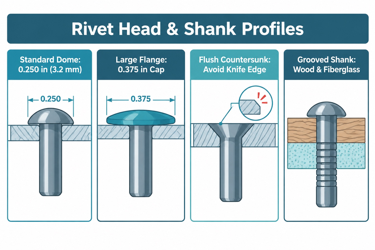
Once the structural family is set, print callouts pick the manufactured rivet head profile. Standard shapes protruding from the top include dome, button, round head rivets, and AN470 universal head shapes. They leave generous bearing metal above the top sheet with zero hole chamfering, while flat head profiles provide a low cylindrical shoulder in very restrictive clearances.
Where sliding parts or exterior skins forbid raised domes, designers specify countersunk rivets so the top of the head of the rivet sits flush with the outer panel. Flush rivets can seat in machined countersinks or formed dimples. For a machined countersink, the top sheet must accommodate the conical head without creating a knife edge, whereas thin skins require a dimpled joint design. Dimensional tables from Jay-Cee Sales & Rivet list IFI Grade 11, 19, and 30 countersunk blind head heights at 0.032 inch on 3.2 mm (1/8-inch) sizes, 0.050 inch on 4.8 mm (3/16-inch), and 0.071 inch on 6.4 mm (1/4-inch).
Cutting a machined countersink completely through a thin sheet leaves a sharp knife edge that tears under shear. FAA AC 43.13-1B governs dimpling versus countersinking on applicable civil aircraft skins. For machine countersinking, sheet thickness is approved based on the geometry of the joint and the height of the conical head, rather than a fixed value.
Standard domes can pull straight through thin aluminum, brittle plastic, or fiberglass panels under peel load. A large-flange head rivet spreads head-side bearing load without enlarging the shank hole, reducing pull-through risk when the sheet and blind-side support can carry the load. On a 3.2 mm (1/8-inch) IFI blind fastener, Jay-Cee Sales & Rivet lists a 0.250-inch standard dome versus a 0.375-inch large-flange cap. Annular grooves on the shank bite directly into the wall of the bore in wood, fiberglass or masonry.
Standard Rivet Sizes, Grip Range, and Hole Clearance Rules
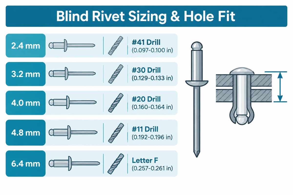
Dimensional sizing mistakes scrap more assemblies than alloy defects. Metric blind rivets under ISO 15977 span 2.4, 3.2, 4.0, 4.8, and 6.4 mm nominal diameters. In Jay-Cee Sales & Rivet catalogs, small solid pins span 1/16 to 7/16 inch and large solid pins span 1/2 to 1-3/4 inch, while rotary forming reaches sub-1 mm pins. Semi-tubular and SPR families follow separate inch or vendor charts rather than one universal millimeter table, so never mix drill clearances across families.
How to Choose a Rivet Size, Grip Range, and Hole Fit
To choose a rivet size, measure the total thickness of all materials being joined at the hole location. Paint and adhesive layers should also be added to the measurement. When a blind rivet is placed in a bore, total thickness should fall within its minimum-to-maximum grip band. Aim for the grip band’s mid-range to account for sheet tolerances.
Metric blind diameters under ISO 15977:2002 and IFI inch series pair with numbered or lettered clearance drills. Jay-Cee Sales & Rivet IFI Grade 11, 19, and 30 tables list these nominal blind sizes and recommended hole clearances:
- A nominal 2.4 mm (3/32 in) blind has a body of 0.090 to 0.096 inch, with a #41 drill hole (0.097 to 0.100 inch).
- Nominal 3.2 mm (1/8 in) blind size pairs a 0.122 to 0.128 inch body with a #30 drill hole (0.129 to 0.133 inch) across published grip steps. Single-shear ratings are 120, 170, and 260 lbf, and tensile ratings are 150, 220, and 310 lbf across grades 11, 19, and 30.
- Nominal 4.0 mm (5/32 in) blind size pairs a 0.153 to 0.159 inch body with a #20 drill hole (0.160 to 0.164 inch).
- Nominal 4.8 mm (3/16 in) blind size pairs a 0.183 to 0.191 inch body with a #11 drill hole (0.192 to 0.196 inch).
- Nominal 6.4 mm (1/4 in) blind size pairs a 0.246 to 0.255 inch body with a letter F drill hole (0.257 to 0.261 inch).
Published metric grip steps in those Jay-Cee IFI tables span 0.8 to 1.6 mm through 12.8 to 15.9 mm on 3.2 mm blind sizes. Larger 4.8 mm and 6.4 mm blind series span 1.6 to 3.2 mm through 22.3 to 25.4 mm, while 2.4 mm sizes cover 0.8 to 6.4 mm.
For protruding-head solid and semi-tubular rivets, under-head length equals stack thickness plus tail-forming allowance; for flush countersunk rivets, nominal length includes the head. Allow roughly 1.5D tail stick-out for bucked civil-aircraft pins under FAA AC 43.13-1B, or 1.0D (3.175 mm on a 1/8-inch pin) for industrial impact pins per Orbitform. Roll-clinched semi-tubular pins use a 50% to 55%D tail stick-out in holes 0.010 to 0.015 inch larger than shank diameter.
Using the correct rivet length and drill prevents three classic shop faults noted by Rosa E Hearn (CFS, Brighton-Best International) in Design World. Under-minimum grip leaves a high mandrel break and loose sheets, and over-maximum grip shears a weak blind bulb. Burred or oversized holes cause mandrel pull-through. Because an audible mandrel snap can still occur on an out-of-grip joint, verify blind-bulb seating on an appropriate rivet against the materials being fastened.
Rivet Materials and Galvanic Corrosion Pairing in Sheet Metal
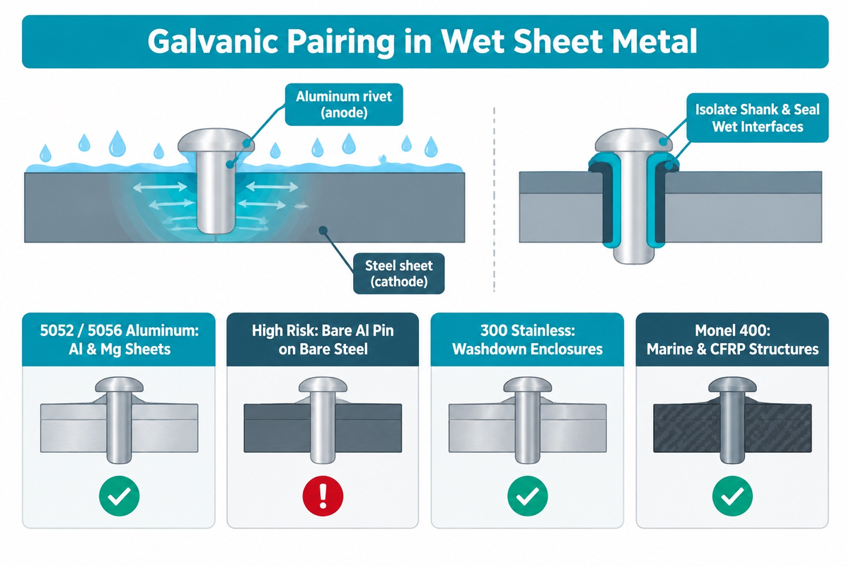
Using the highest tensile catalog alloy for outdoor use fails unexpectedly when moisture bridges two metals of different potentials and causes galvanic corrosion. Because a fastener head and tail expose tiny surface area next to wide panels, an anodic fastener suffers concentrated current density and dissolves rapidly across wet sheet-metal joints.
Can you use aluminum rivets on steel?
Using bare aluminum rivets on bare carbon steel or stainless steel in outdoor, marine, or road-salt use causes rapid galvanic corrosion of the thin aluminum shank. Select compatible fasteners matched to the exposure and base metal, or isolate coated joints with dielectric barriers and sealant.
NASA RP-1228 and Assembly Magazine’s report on magnesium joining reinforce this anode-to-cathode area rule. When joining dissimilar materials in rain or road salt, pick a rivet material matching or slightly more noble than the sheets. Check the mandrel stem alloy on open-end blind hardware too, because plain steel stem stubs rust inside aluminum sleeves outdoors unless sealed or ordered in stainless steel.
Materials Used Across Sheet-Metal Rivet Families
Engineers need to weigh shear rating, cold formability, and conductivity across 10 alloy and polymer groups, and balance salt exposure. The table below provides guidance when specifying stainless steel rivets for washdown cabinets, copper rivets for ground straps, and brass rivets across different materials.
| Rivet Material Group | Shear and Cold-Forming Profile | Compatible Base Sheets and Duty | High-Risk Bare Pairing in Wet Electrolytes |
|---|---|---|---|
| 1100 / 5052 / 5056 aluminum | Soft, low pull force, moderate shear | 5000/6000 aluminum boxes, magnesium housings (5052/5056) | Large bare carbon steel, stainless, or copper sheets outdoors |
| 2017 / 2024 / 2117-T4 aluminum | High fatigue shear; 2117-T4 (“AD”) driven cold | Alclad and anodized aircraft skins per approved data | Unsealed carbon-fiber (CFRP) or bare stainless in salt air |
| 6061 structural aluminum | Medium-high strength and weather resistance | Extruded aluminum frames, trailers, marine superstructures | Wet contact with bare copper, brass, or uncoated carbon steel |
| Zinc-plated low-carbon steel | High shear, ductile forming, sacrificial zinc coat | Painted or galvanized steel brackets, appliance chassis | Marine immersion or acid washdown once thin zinc depletes |
| Boron / alloy steel | Heat-treated to pierce UHSS or hold lockbolt preload | Coated automotive SPR joints and heavy truck frames | Uncoated use in wet aluminum trays without adhesive |
| 300-series stainless steel | High shear, rapid work-hardening, higher pull load | Food/medical stainless enclosures, isolated aluminum frames | Thin bare 1100 aluminum in stagnant saltwater crevices |
| 400-series stainless steel | Magnetic; martensitic grades harden by heat treatment while ferritic grades cannot; mild corrosion resistance | Appliance hinges, exhaust shields, mild outdoor steel | Chloride splash zones where pitting trails 316 or Monel |
| Deoxidized copper | Soft, malleable, high electrical/thermal conductivity | Copper busbars, roof flashing, heavy leather burr sets | Bare aluminum or galvanized panels (runoff causes pitting) |
| Yellow / cartridge brass | Stronger than pure copper, smooth roll clinch | Luggage hardware, electrical contacts, friction linings | Wet aluminum/magnesium contact or ammonia environments |
| Monel 400 & nylon push-pins | Monel resists seawater; related nylon clips insulate light panels | Marine/CFRP structures (Monel); PCB/trim clips (nylon) | Bare magnesium (Monel); primary load or high heat (nylon) |
Mixed-metal assemblies often pair stainless brackets with painted aluminum or pass through materials like carbon-fiber laminates. Non-conductive primers and insulating washers reduce electrical contact, while sealant excludes moisture. Complete electrical isolation requires insulating the rivet shank where it would contact dissimilar materials.
Rivets vs. Welding vs. Bolts: Which Permanent Joint Fits Your Assembly?
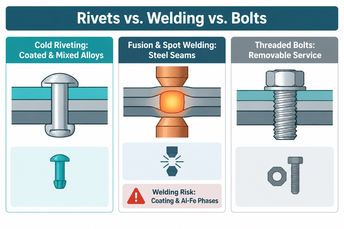
In sheet metal fabrication, choose cold mechanical riveting for coated, heat-sensitive, or dissimilar sheets that distort or embrittle under welding heat. Use resistance spot welding for discrete steel lap joints and bolts for joints that must be disassembled.
On weldable steel sections, fusion welding creates a continuous, leak-tight seam. In contrast, resistance spot welding joins sheets at a discrete location. Additional sealing may be required to achieve a leak-tight seal. A 2025 review published in Frontiers in Materials (Vol. 12, Du et al.) states that the multi-material structure of vehicles places limitations on welding. Welding thin pre-painted metal sheet burns off protective zinc coatings, and welding steel directly to aluminum forms brittle iron-aluminum intermetallic phases. The unretained nuts and bolts can also come loose due to vibration.
Separate load tiers when engineers use rivets for fastening materials that cannot weld cleanly. Structural rivets are an essential cold-joining option alongside bolts and adhesives, whereas non-structural open-end blind hardware fits light enclosures. Primary shear and fatigue joints rely on solid pins, mechanically locked structural blind fasteners, lockbolts, or SPR. Installation damage should be considered for joints used on structures composed of polymers or brittle materials. Heavy impact bucking or high radial hole expansion crushes resin matrices and triggers fiber delamination in CFRP, while high upsetting pressure cracks brittle 0.150-inch SMC panels. On fragile laminates, rivets may require low-force semi-tubular roll clinching, soft alloys with backing washers, or pre-holed upper layers.
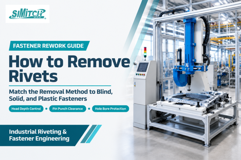
Conventional solid, tubular, and break-mandrel blind rivets are removed destructively rather than unscrewed during maintenance. Technicians follow controlled drill-out steps to remove rivets without enlarging holes before setting replacement hardware.
Matching Rivet Types to Installation Tools and Automated Riveting Systems

After specifying the right rivet to use on a drawing, match station kinematics, anvil support, and force capacity to shank geometry and line takt time. Handheld pullers fit low-volume bench work, while guided orbital, radial, hydro-pneumatic, and servo presses control forming loads in production cells.
What is the difference between a rivet machine and a rivet gun?
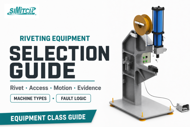
A rivet gun is a portable handheld manual, battery, or pneumatic tool for field pulling or bucking, whereas a rivet machine is a frame-mounted station applying guided, repeatable forming force. Maintenance crews use a portable rivet gun or hammer for large frames. Bench and automated machines instead monitor axial, orbital, radial, or C-frame strokes across volume assemblies used in manufacturing.
Engineers partition industrial rivet work into forming motion and power source for production lines. In Assembly Magazine’s report on orbital and radial forming, rotary cold heading is contrasted against impact presses by Chuck Rupprecht (BalTec), Bryan Wright (Orbitform), and Phil Huber (Taumel). An orbital head drives a non-rotating peen tilted at 3 to 6 degrees (typically 900 to 1,200 rpm), while radial machines trace an 11-lobe rosette path. Assembly Magazine describes orbital and radial applications using sub-1 mm pins and reports servo forming forces up to 38,500 lbf. It also reports forming malleable shanks up to Rockwell 35C and quotes BalTec’s Rupprecht on using force-and-distance monitoring to prevent shank swelling in pivot applications.
When plants use a rivet in automated cells, published machine ratings show how force scales across industrial riveting equipment. In SIMITCH’s published specifications, servo riveting assembly systems pair an 80 kN power unit with a 200 mm stroke and 0 to 333 mm/s ram speed. SIMITCH self-piercing configurations span 50 kN and 75 kN hydro-pneumatic presses plus 5T and 8T servo C-frames with 100 mm or 200 mm strokes. In TWI paper SAE 2001-01-0979, prototype 850 mm deep-throat C-frames targeted linear deflection under 7 mm and angular deflection below 1 degree at 64 kN (steel) and 53 kN (composite).
Servo and hydro-pneumatic controllers sample force-displacement curves every cycle to catch missing pins or gross thickness drift. Still, curve windows have non-detection blind spots, such as part tilt or micro-undercut shifts within peak force bounds. In-line curve monitoring complements destructive cross-sectioning and peel or shear qualification on sample stacks.
You’ll need to provide the following six inputs for defining joints before requesting a quote for an automated station:
- Precise sequence of punch-to-die sheet stacks, specifying thickness of each layer, coatings, adhesives and alloy tempers (ex: tensile strength or Rockwell hardness).
- Fastener family and print dimensions, covering nominal diameter, length or grip band, and semi-tubular bore depth or SPR hardness class.
- Part 3D CAD geometry, flange width, minimum edge distance, and the deepest C-frame throat to clear surrounding walls.
- Target joint mechanical function to determine if it’s a rigid structural clamp, sealed enclosure seam, or a controlled clearance rotating pivot.
- Required cycle rate in fasteners per minute, and manual versus robotic part loading, as well as blow-tube versus magazine feeding.
- Joint qualification plan combining force-displacement window logging with destructive cross-section interlock and peel or shear acceptance limits.
Multi-Material Lightweighting and Force-Monitored Riveting in Manufacturing
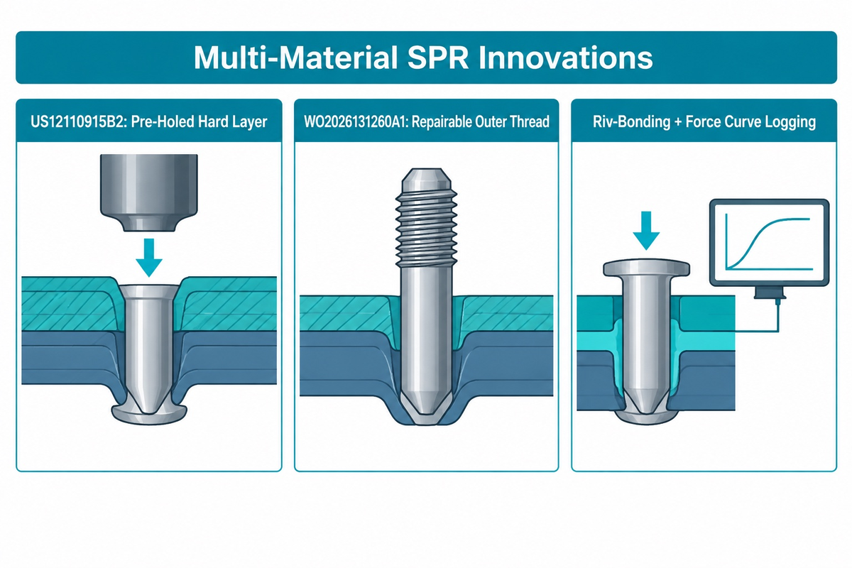
In modern plants, rivets are commonly used wherever lightweight structures combine alloys that can’t be spot welded cleanly. EV battery enclosures and mixed body-in-white frames pair 6000-series aluminum extrusions with ultra-high-strength steel (UHSS), magnesium castings, and composite lids. Mechanically locked structural blind rivets are used in rail car shells and used in construction curtain-wall subframes facing wind vibration.
Recent patents cite examples of fastener engineers addressing brittle layer cracking and collision repair (all cited patents belong to their named assignees). U.S. Patent US12110915B2 was granted on October 8, 2024 to Ford Global Technologies LLC (inventors Aindrea McKelvey Campbell and Amanda Kay Freis). It addresses CFRP delamination and pin buckling by placing a clearance hole through a hard, upper or middle, layer and self-piercing a ductile lower layer. International application WO2026131260A1 was filed by Tucker GmbH and Newfrey LLC and published in 2026 (inventors Vadim Sartisson and Steffen Mathia). It discloses a grooved outer-thread self-piercing pin punched without pre-drilled holes into high-strength steel and EN AW 5182 aluminum, allowing rotational unscrewing during repair.
Plants increasingly pair structural epoxy adhesive with SPR or locked blind hardware (riv-bonding) alongside cycle-by-cycle servo force-displacement logging. For die-button checks and stack-up rules, see our self-piercing riveting joint design guide.
Frequently Asked Questions About Types of Rivets
What is the most common type of rivet used in industry?
Open-end break-mandrel blind rivets (POP rivets) are among the most widely used general-purpose industrial rivets because one operator sets them quickly from one side.
They are used in many sheet-metal cabinets, HVAC ducts, machine covers, brackets, equipment housings, lighting enclosures, and appliances, and are commonly used in home and field repair kits. The primary aircraft skins use fatigue resistant solid aluminum pins. Multi-material automotive bodies use self-piercing rivets and mechanically locked structural blind hardware for high joint stiffness.
Which type of rivet is used in aircraft structures?
Aircraft structures primarily use solid 2117-T4 (“AD”) aluminum alloy rivets in universal-head AN470/MS20470 and 100-degree flush MS20426 styles.
Where closed wing boxes block backside access, approved mechanically locked structural blind fasteners provide one-sided installation. Conventional titanium or steel lockbolts used in critical load paths require two-sided access for the installation and swaging of the collar. Follow applicable approved design or repair data and manufacturer instructions; where manufacturer repair instructions are unavailable on nonpressurized civil aircraft areas, assess whether FAA AC 43.13-1B guidance applies.
What type of rivets are used on aluminum boats and gutters?
Light non-structural aluminum rain gutters and above-waterline trim panels commonly use closed-end sealed 5000-series aluminum blind rivets paired with compatible sealant.
Below the waterline or along structural hull chines, ribs, and frames, marine builders prefer bucked solid aluminum pins (such as 2117-T4 or 5052/5056 alloys) wet-set with marine elastomeric compound. Always check joint load requirements prior to blind fastener substitution on hull plating. Avoid open-end aluminum pop fasteners with plain carbon-steel stems in wet service, because trapped steel stubs rust, stain panels, and let water seep through.
What are split rivets and drive rivets used for?
Both fasteners handle light, non-structural attachments without mandrel-pulling guns.
Bifurcated two-pronged pins pierce soft materials like leather, luggage fiberboard, and thin plastic, and then fold flat; drive rivets spread slotted legs inside masonry or nameplate holes.
What type of rivets are best for leather and jeans?
Double-cap tubular rivets and solid copper burr-and-rivet sets are best for leather craft and heavy denim stress points.
Brass posts leave both ends smooth on belts and bags. Hand-peened copper posts with burrs hold seams on workwear without snagging.
Why are hot-driven rivets no longer used in heavy steel construction?
Heavy steel bridges and building frames replaced hot-driven rivets with high-strength structural bolts and arc welding for safer crews, faster erection, and verifiable joint performance.
Multi-person crews forged and threw red-hot steel pins on high scaffolding, and variable clamp tension across gussets was a byproduct of uneven cooling shrinkage. Properly installed tension control bolts provide controlled bolt pretension, and inspected structural welds transfer loads through fused metal. Cold-formed rivets remain useful in aircraft skins, EV battery trays, appliances, and thin or dissimilar sheet assemblies because they avoid welding heat, coating burn-off, and thermal distortion.
Can structural blind rivets replace solid rivets in high-vibration joints?
Mechanically locked structural blind rivets often replace solid pins in approved truck bodies, rail cars, and heavy enclosures where backside bucking access is unavailable.
Structural blind rivets positively retain the mandrel via a locking mechanism, whereas the common rivet design doesn’t provide positive mechanical retention. Under certain types of vibration, a portion of the retained mandrel can be lost, resulting in a reduced shear capacity. Because the locked stem is in the shear zone, structural blind hardware carries a dynamic shear load. Airframes, bridges, and other safety-critical structures still require approval by the OEM or an engineer after it’s confirmed that shear allowables and hole tolerances are acceptable.
References & Sources
- Federal Aviation Administration (FAA): AC 43.13-1B Change 1, Aircraft Inspection and Repair
- NASA Lewis Research Center: NASA RP-1228, Fastener Design Manual (Richard T Barrett)
- ISO: ISO 15977:2002 (Confirmed 2023), Open-End Blind Rivets (2.4–6.4 mm)
- ISO: ISO 15973:2000 (Confirmed 2026), Closed-End Blind Rivets
- The Welding Institute (TWI): SAE 2001-01-0979, Lightweight Self-Piercing Riveting Equipment
- Frontiers in Materials (2025, Vol. 12, Du et al.): Mechanical Joining and SPR in Multi-Material Structures
- Assembly Magazine (Jim Camillo): What’s New With Orbital and Radial Forming
- Assembly Magazine (John Sprovieri): Assembling Magnesium Parts and Galvanic Corrosion
- Universal Rivet Inc.: Semi-Tubular and Full-Tubular Rivet Specifications
- Jay-Cee Sales & Rivet Inc.: IFI Grade 11, 19, and 30 Blind Rivet Tables
- Design World (Rosa E. Hearn, CFS): Typical Riveting Faults and Avoidance
- USPTO / Google Patents: US12110915B2 (Ford Global Technologies LLC, 2024)
- WIPO / Google Patents: WO2026131260A1 (Tucker GmbH & Newfrey LLC, 2026)


WHY WE WRITE THIS
About SIMITCH
SIMITCH develops sheet-metal joining equipment for clinching, riveting, servo pressing, pneumohydraulic drive and hot-melt connection applications. Our engineering team starts with the material stack, access envelope, cycle target and acceptance method before recommending a machine route.
Founded in 2006 in Taicang, Jiangsu, SIMITCH combines research and development, in-house production and global sales. These guides turn field experience into practical decision support for process engineers, plant teams and industrial buyers.
OUR EXPERIENCE
Since 2006
Equipment engineering, machining, assembly and joint validation under one manufacturing system.
OUR EXPERTISE
Five joining routes
Clinching, riveting, SPR, precision press-fit and hot-melt connection for production lines.