Get in touch with Suzhou Simitch Machinery Co., Ltd Company

Updated July 2026
Quick Decision Inputs
| Part evidence | Drawing, joint locations, access envelope, support points |
| Material evidence | Grade, thickness order, coating, temper, surface condition |
| Production evidence | Joint count, cadence, changeovers, utilities, data interfaces |
| Approval evidence | Section geometry, mechanical tests, process window, monitoring plan |
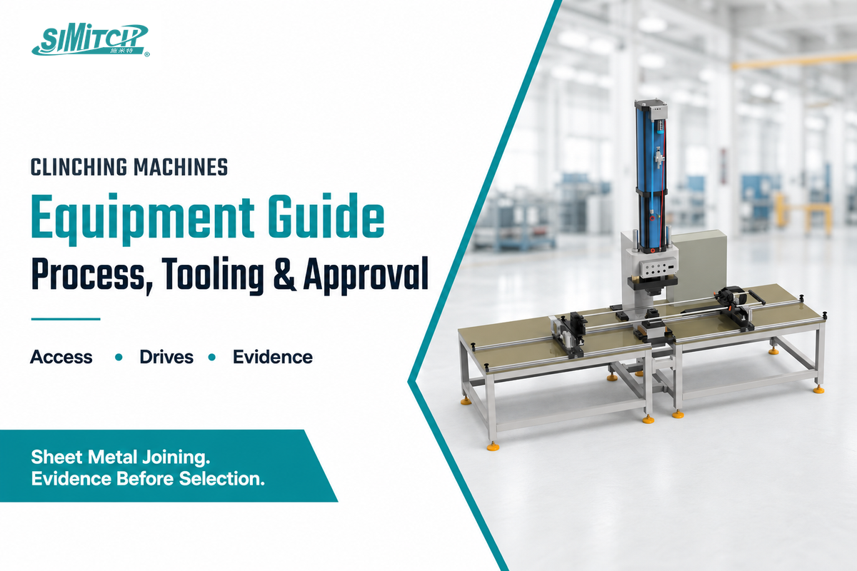
Clinching Machines & Equipment refers to the complete joining system—press or tongs, matched punch and die, frame, controls, guarding, and part support—used to form a mechanical interlock between sheet layers without a separate fastener. Select the system from the part backward, not from a press catalogue forward. Maximum force, a servo label, or a clean sample button cannot prove that tooling will reach the joint, the sheet stack will form reliably, or the finished connection will survive its service load.
This guide explains how the joint forms, how equipment families differ, which hidden constraints change the recommendation, and what evidence belongs in a production RFQ. Readers who already have a defined part can also review Simitch’s clinching machines and equipment solutions; the commercial page covers available solution paths, while this article concentrates on engineering decisions and approval evidence.
Direct answer: Clinching equipment forms a mechanical interlock by pressing sheet layers between matched punch and die tooling. Sound selection must fit the access geometry, material stack, production pattern, controls, safety concept, and test plan; rated force alone is not an approval rule.
What matters most
- Visible button formation is evidence, not complete proof of joint performance.
- Access, reaction-force support, and part presentation can rule out an architecture before press capacity is compared.
- Static tensile-shear results do not automatically approve cyclic, corrosive, or differently constrained service.
- Monitoring can detect a deviation, but diagnosis still requires tooling, alignment, material, utility, and maintenance checks.
What Is Sheet Metal Clinching, and How Does the Joint Form?
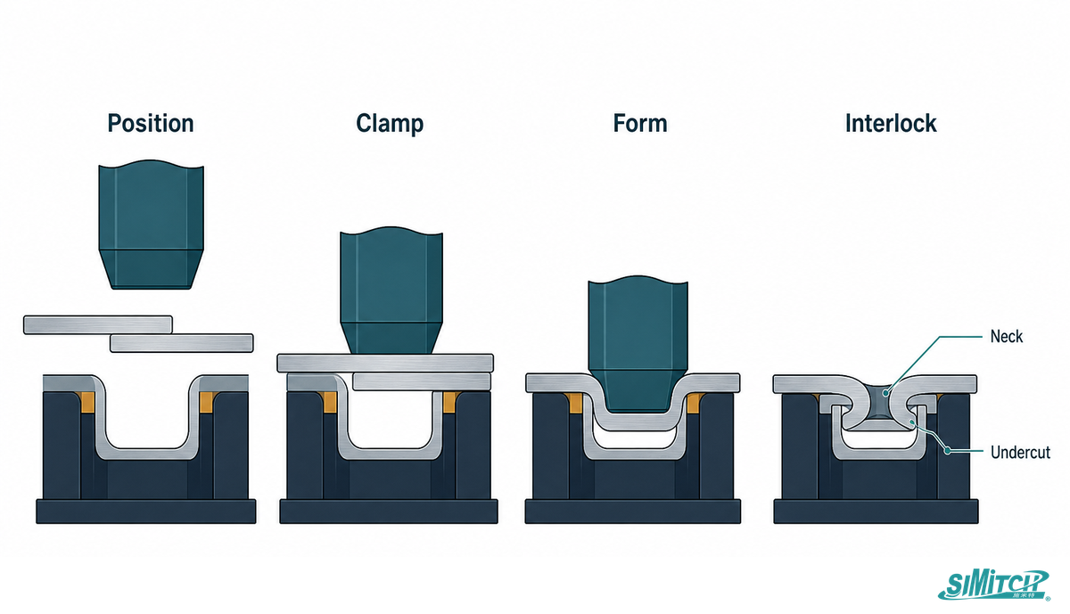
Sheet metal clinching is a cold-forming method that joins overlapping, sufficiently formable sheets without a separate rivet or a fused weld nugget. During forming, the punch drives the stack into a matched die, material flows laterally, and the resulting neck plus undercut creates a mechanical interlock after the tools release.
What is the process of clinching sheet metal?
Process flow is mechanical and local: position the sheets, clamp or support the stack, form it between punch and die, then release the tools and inspect the button. Unlike spot welding, the operation does not depend on melting a nugget. Unlike conventional riveting, it does not add a separate fastener.
- Position the stack — locate the sheets and support the surrounding flange so the intended joint center stays aligned.
- Close the tooling — bring the punch and die together while controlling stack movement and off-axis loading.
- Form the interlock — displace material through the die geometry to create the neck and undercut without intentional melting.
- Release and inspect — open the tools, verify the visible formation, and move the sample into the defined approval plan.
Useful cross-section terms include neck thickness, interlock or undercut, bottom thickness, cracks, and local thinning. Those features depend on the material and tool system together. A sheet metal clinching tool must therefore be evaluated with its production stack, not by button diameter alone. Similar visual appearances can hide different section geometry.
Common mistake: treating “button formed” as the end of validation. Formation confirms that the operation occurred; it does not establish load capacity, fatigue life, corrosion durability, or repeatability.
Clinching Machine Types: From Handheld Tools to Robotic Cells
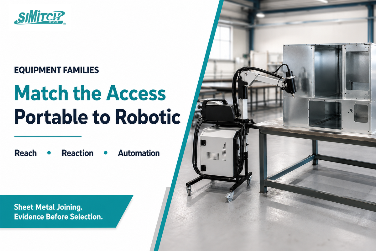
Clinching machine types differ mainly in how they reach the joint, react forming force, support the part, present multiple joint locations, and connect to production controls. A 2017 open review ties joint quality to clinch type, equipment adjustment, and loading direction, so handheld, fixed, and robotic equipment should not be read as a simple upgrade ladder.
Research published by Fraunhofer and Paderborn in 2024 describes driven C-frames mounted on industrial robots for car-body joining. That is evidence for one flexible architecture, not a rule that robotic equipment is best for every automotive component. For a small part that can be presented consistently, a stable bench press may be the better choice.
| Equipment family | Access and production pattern | Main advantage | Limitations / not suitable for |
|---|---|---|---|
| Manual hand tool | Open edge, low joint count, repair or trial work | Low infrastructure burden | Operator effort and limited traceability |
| Suspended tong | Large part with reachable flanges | Tool follows the workpiece | Balancer, hose, reaction, and ergonomic constraints |
| Portable C-frame | Edge access with one defined throat path | Rigid two-sided tooling route | Deep internal joints may exceed throat access |
| Portable X-frame | Alternative approach around local obstructions | Different jaw kinematics | Clearance and support still require a part check |
| Bench or floor press | Part brought to a fixed joint station | Repeatable presentation | Awkward or very large parts may be hard to load |
| Fixed C-frame press | Defined reach and dedicated operation | Stable reaction-force path | Frame reach and part support are fixed constraints |
| Multi-point fixture | Several repeatable joints on one assembly | Parallel or sequenced productivity | Higher fixture and alignment complexity |
| Indexed station | Repeated parts moving through defined positions | Controlled cadence and part flow | Changeover and accumulation logic must be engineered |
| Gantry or robotic cell | Distributed joints and programmable presentation | Flexible motion and line integration | Payload, frame mass, reaction forces, guarding, and cycle path |
Simitch publicly organizes its range into nine press or equipment families and separates portable C-type and X-type routes. Buyers can use those labels to begin a conversation, but a category name still needs force, stroke, utilities, weight, access, and trial evidence. Its portable and handheld clinching equipment page is therefore a family reference, not a substitute for a part review.
Pneumatic, Hydraulic, or Servo: What Changes?
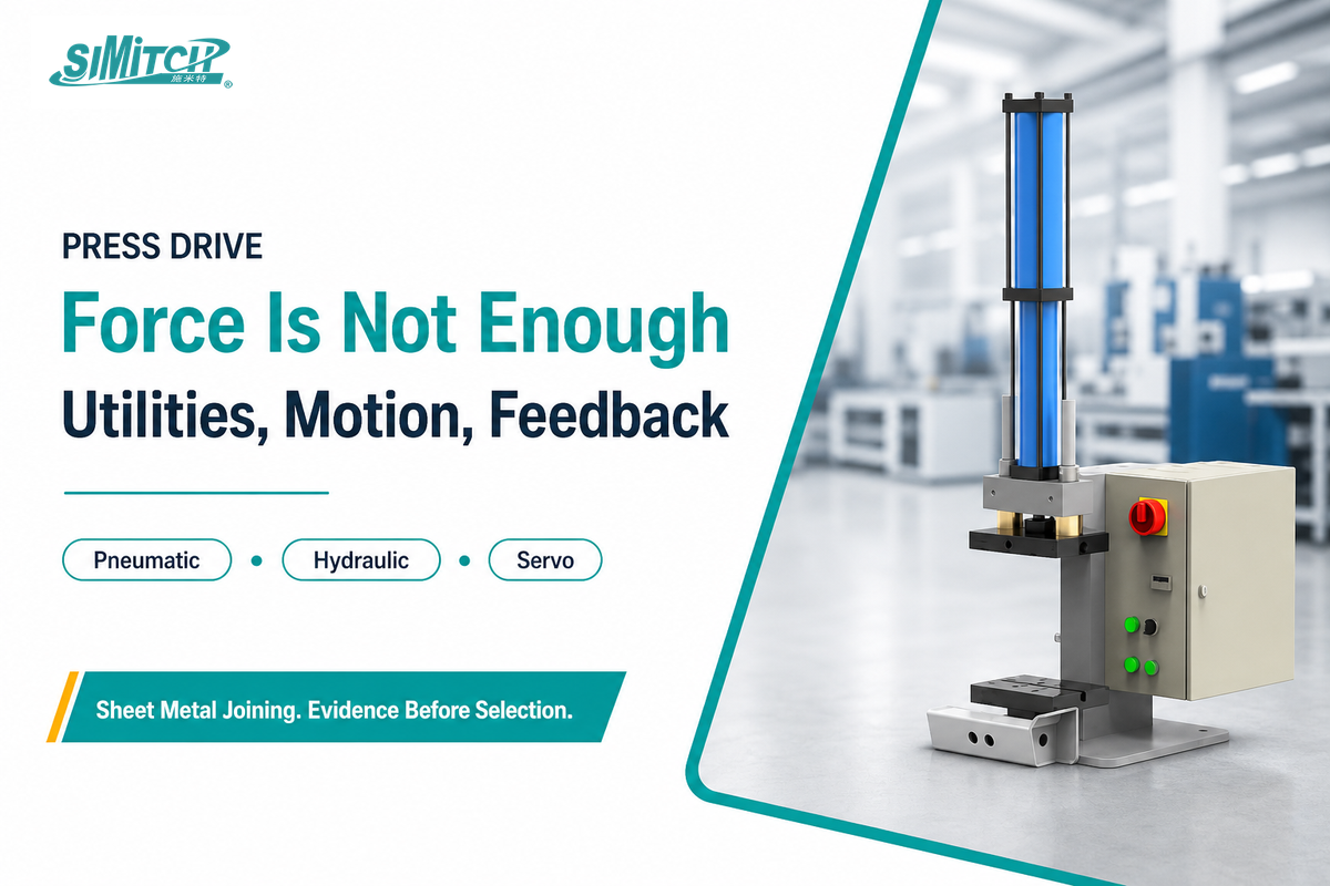
Pneumatic, hydro-pneumatic, hydraulic, and servo drives change how a press generates motion and force, which utilities it needs, and what feedback can be captured. They do not remove the need to qualify the tooling, machine deformation, joining velocity, alignment, and material stack on the actual application. A peer-reviewed process-chain review likewise treats design, joining, and operational behavior as connected evidence.
| Drive route | What changes | Useful when | Qualification boundary |
|---|---|---|---|
| Pneumatic | Compressed-air supply, valve timing, pressure stability | Required force and control envelope fit the architecture | Air quality and pressure behavior remain process inputs |
| Hydro-pneumatic | Air-powered approach with intensified working stroke | Compact force generation and plant air suit the station | Booster sizing and fluid/air condition require maintenance |
| Hydraulic | Hydraulic power unit, pressure control, heat and leak management | Duty and force profile justify the utility package | Force capacity alone does not prove joint geometry |
| Servo-electric | Programmable motion, position feedback, curve acquisition | Recipe control and traceability are material requirements | Control resolution cannot compensate for poor access or tooling |
Simitch publishes an attributed fixed-press family envelope of 18.4–990 kN and a suspended hand-tong envelope of 45–75 kN. Those are supplier family ranges, not universal joint forces and not a promise that every value is available in every frame, stroke, or control arrangement. Review the current pneumatic and servo clinching press families before requesting a specific configuration.
Research from 2022 reports that changing the press system can change interlock through joining velocity, press deformation, and angular or lateral tool misalignment. In practice, compare drives by the controlled outcome and machine behavior, then approve the joint on the complete setup.
Tooling and Access Geometry: The Constraint Buyers Miss
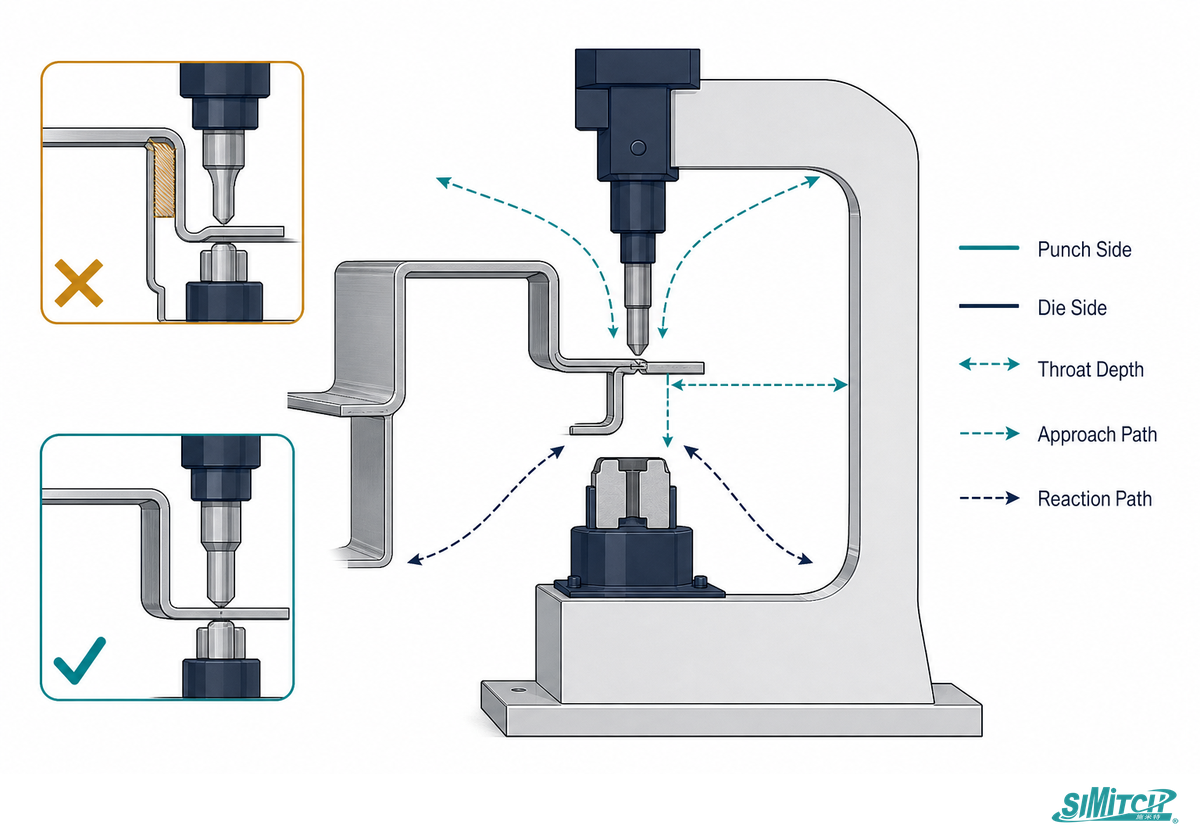
Tooling access can disqualify a nominally powerful clinching press because conventional joints need coordinated punch-side and die-side access, a workable approach direction, sufficient throat depth, and a reaction path that does not distort the assembly. Part drawings must therefore lead tooling selection, not follow it.
“The deeper the joint is in the center of the workpiece, the larger the clinching machine frame will need to be.”
One United States patent discloses an offset die and anvil arrangement intended to reach narrower flanges. Another patent describes a punch taper of 20°–35°. These disclosures show that access and punch geometry are engineered variables; a patent claim is not production-performance evidence for a different material or joint.
Consider a cabinet panel with a joint line well inside the outer edge. Despite adequate rated force, a portable tool can still fail the layout because the frame cannot clear a return flange, the die side is blocked by a rib, or the panel lacks support against reaction force. Moving the joint, changing the approach, adding a fixture, or selecting another joining method may be cheaper than specifying a larger press after tooling is frozen.
Document before quotation: joint-center coordinates, edge distance, throat path, flange width, punch-side clearance, die-side clearance, approach direction, obstruction zones, and permitted witness-mark side.
Material Stack, Coatings, and Joint Geometry
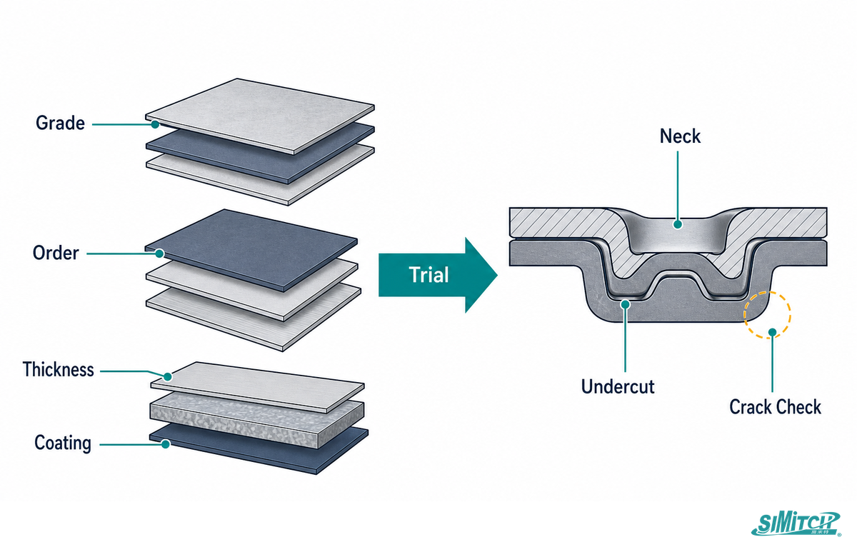
Every clinching trial needs the actual sheet stack, not a label such as “aluminum and steel.” Grade, thickness order, temper, coating, pre-deformation, number of layers, die-side material, fit-up, and surface condition can change material flow, neck thickness, undercut, cracks, and the resulting failure mode.
Research published in 2026 on three-layer aluminum-steel shear clinching treated inner punch diameter, preload, application class, die-side material, force-displacement response, and joint geometry as interacting variables. That scope argues against transferring a tool recipe from one stack to another merely because total gauge is similar.
An earlier robustness study examined 1.5 mm HCT590X steel with 2.0 mm EN AW-6014 T4 aluminum. Its force-displacement and section evidence again shows why a peak-force value is not enough when thickness and pre-strain change.
Can coated or dissimilar sheets be clinched?
Coated or dissimilar sheets may be clinchable, but feasibility must be established with the production material order, coating system, surface condition, and functional load. Forming success on day one does not answer whether coating damage, trapped moisture, a galvanic couple, cleaning chemistry, or outdoor duty will change service performance.
One 2025 two-dimensional numerical study of aluminum-aluminum joints modeled pits of 50 µm and 100 µm. Pitting near the internal neck reduced modeled high-cycle fatigue life. This narrow environmental-risk example is not a universal allowance or a substitute for corrosion and fatigue tests on the real assembly.
Material-stack record: include certificates or exact grades, individual thicknesses in punch-to-die order, coating name and thickness where known, temper or work history, layer count, surface treatments, lubricants or contamination controls, and representative cut samples.
How to Select a Clinching Machine for Your Part and Production Plan
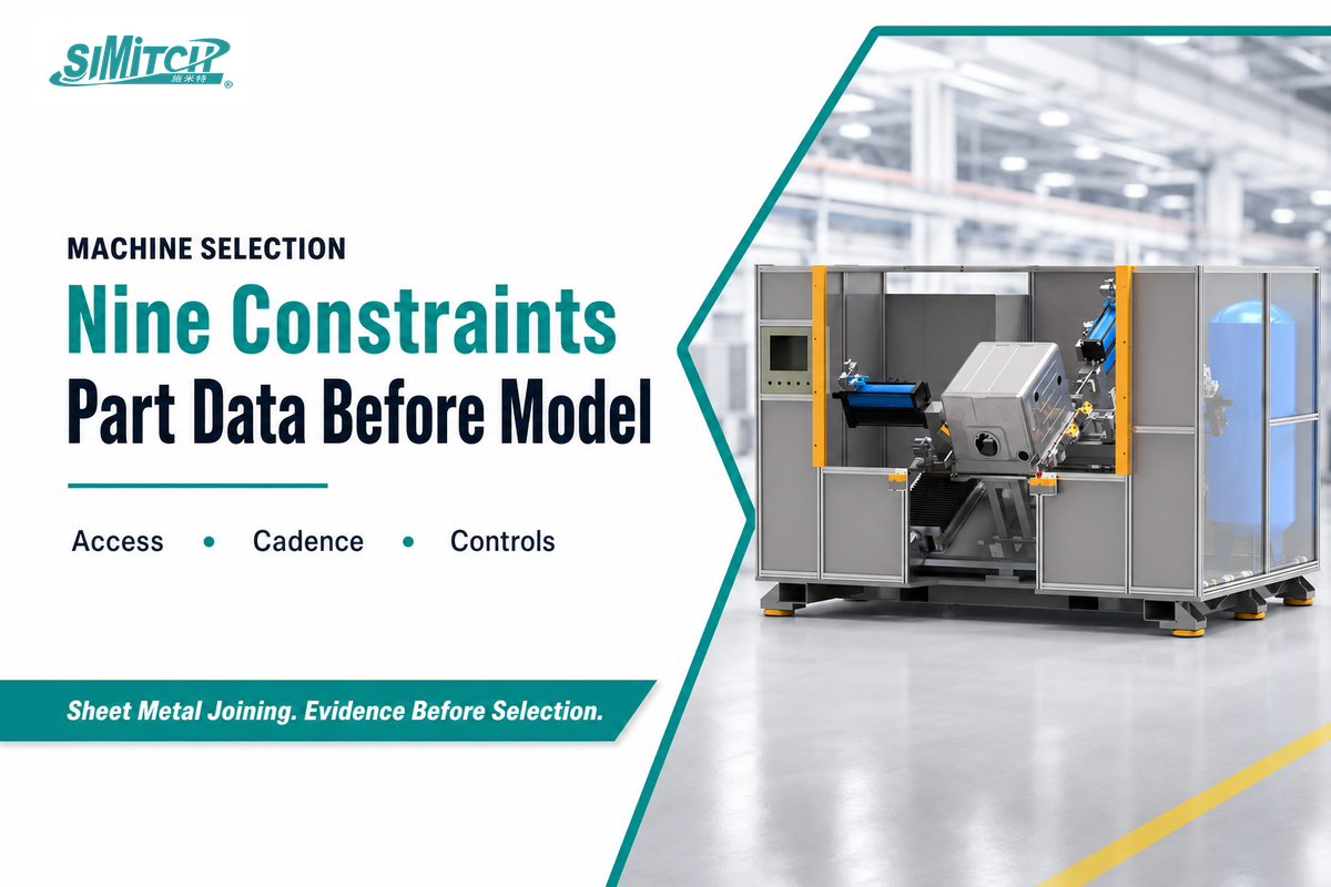
Defensible clinching machine selection follows nine linked constraints: part access, joint pattern, material stack, acceptance evidence, part support, production cadence, changeover, utilities and data, and project ownership. A peer-reviewed process-chain review supports evaluating design, joining, and operational behavior together; the nine-field structure here is an editorial decision tool.
| Visible specification | Hidden bottleneck | Risk owner | Evidence to request | Decision that changes |
|---|---|---|---|---|
| Maximum force | Actual stack and tool process window | Process engineering | Trial curve plus sectioned joints | Drive and press size |
| Throat depth | Obstructions along the approach path | Product design | Marked drawing and clearance model | Frame or joint location |
| Cycle rate | Part handling and tool travel dominate | Industrial engineering | Time study with full motion path | Manual, indexed, or robotic route |
| Joint count | Pattern, simultaneity, and fixture alignment | Manufacturing engineering | Joint map and sequence | Single or multi-point tooling |
| Portable label | Tool mass, hose routing, reaction, ergonomics | Operations and EHS | Handling trial and risk review | Balancer or fixed station |
| Servo control | Data ownership and acceptance logic | Quality and controls | Signal list and traceability plan | Controller and storage scope |
| Changeover time | Tool, fixture, recipe, and verification work | Production | Variant matrix and first-off plan | Dedicated or flexible equipment |
| Joint sample | No agreed acceptance owner or service load | Product and quality | Signed test and acceptance plan | Trial scope and release timing |
| Turnkey quote | Undefined guarding, installation, interfaces, training | Project management | Responsibility matrix and site data | Scope, price, and schedule |
Consider a large HVAC panel as a worked example. Distributed joints and two-sided access first point toward a movable tool or indexed fixture. Panel width then raises support and distortion questions. Several product variants make changeover and recipe control relevant, while a traceability requirement adds signal and record-retention work. None of those inputs yields a responsible model number without a drawing and part trial, but they do narrow the architecture and expose who must approve each boundary. Simitch’s application-built clinching systems for HVAC and appliances show the application route after these inputs are prepared.
Selection rule: ask the supplier to explain which input changed the recommendation. If the answer is only maximum kN, the access, support, acceptance, and production evidence is still incomplete.
Worked sample-run record with illustrative values
The figures below show how a buyer can complete a measurable trial record; they are not Simitch ratings, universal process limits, or acceptance recommendations. Replace every value with the drawing, product requirement, site condition, and signed test plan for the actual part.
| Record field | Illustrative entry | Buyer action |
|---|---|---|
| Sheet stack | 1.0 mm upper sheet + 1.2 mm lower sheet | Replace with certified grades, coatings, and punch-to-die order. |
| Section targets | 8.0 mm button, 0.50 mm interlock, 0.40 mm minimum neck | Set limits only after representative section and performance work. |
| Access model | 85 mm side clearance, 420 mm throat, 0.20 mm permitted fixture movement | Check the full approach path, not one section view. |
| Production demand | 12 joints per part and 240 joints/min at target cadence | Discount theoretical output for loading, handling, and changeover. |
| Loaded time | 7.5 hours per shift, 15 hours/day, 5 days per week | Use the real shift calendar and planned downtime. |
| Site utilities | 6 bar air at 500 L/min; 400 V, 50 Hz, 3 kW electrical basis | Confirm loaded pressure, power quality, isolation, and local code. |
| Motion basis | 3 sec cycle, 120 mm working stroke, 40 mm/s approach | Separate forming time from part handling and safety reset. |
| Trial sampling | 30 joints total, 10 joints per setting, 2 hours observation | Define randomization, section locations, and custody of samples. |
| Static screen | 1.2 kN average, 0.9 kN minimum, 10 joints tested | Replace with product-owned limits and failure-mode criteria. |
| Cyclic screen | 0.4 kN peak at 5 Hz across 6 joints | Match load direction, ratio, environment, and life requirement. |
| Environment | 240 hours exposure at 23 °C, followed by 48 hours dry-back; site humidity recorded | Use the buyer’s approved corrosion or conditioning method. |
| Monitoring setup | 10 kHz acquisition, 0.01 mm position resolution, 24 hours example retention, force window set from the approved trial baseline | Verify what the proposed controller actually records and retains. |
| Reaction trigger | 0.20 mm geometry drift, product-owned load-change limit, 2 joints for containment, 30 min review window | Assign stop, segregation, review, and restart authority. |
How Do You Validate a Clinched Joint? The 4-Stage Joint Approval Ladder
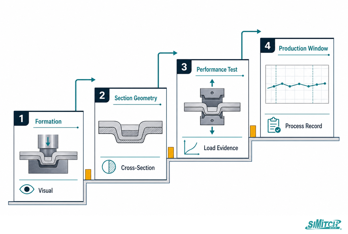
Production approval for a clinched joint passes through four evidence stages: confirm formation, measure section geometry, test mechanical performance for the application, and prove a controlled production window. This ladder is a project method, not an ISO standard, and every acceptance limit must come from the product’s requirements and representative tests.
| Stage | Evidence | Typical checks | Acceptance owner |
|---|---|---|---|
| 1. Formation | Repeatable formed button without obvious damage | Location, button appearance, cracks, marking, distortion | Process engineering |
| 2. Section geometry | Measured cross-sections from the defined sample plan | Neck thickness, interlock, bottom thickness, symmetry | Quality or laboratory |
| 3. Performance | Tests that represent the product function | Static load, failure mode, peel/shear direction, fatigue or environment where required | Product engineering |
| 4. Production window | Repeatability and a documented reaction plan | Curve limits, sample frequency, tool-life interval, traceability, containment | Manufacturing plus quality |
ISO 12996:2013, confirmed current in 2024 on the ISO catalogue, defines a tensile-shear specimen geometry and test procedure for single mechanical joints. Its scope is narrower than a complete clinching quality system. It can inform one test, but it does not supply universal pass/fail values for a finished product.
In one 2026 study on pre-deformed 6060 aluminum specimens, destructive load changed from 607 N to 712 N across the reported conditions. That study-specific movement illustrates why material history belongs in the sample plan; it is not a general clinching capacity range.
How do you know a clinched joint is strong enough?
Joint strength is acceptable only when representative specimens meet the product owner’s documented criteria with the required margin and repeatability. Visible geometry and force-displacement curves can support control, but they must be linked to destructive or functional evidence that represents the actual loading direction and service condition.
Static approval must be separated from service-life approval. ISO’s public catalogue page identifies ISO/TR 12998:2019 as guidance for fatigue testing of mechanical joints. For cyclic service, define the representative load direction, range, local stiffness, duty, environment, and acceptance criteria before selecting the applicable fatigue method. This article does not paraphrase clauses that were not visible on the public page.
Engineering note: keep the static ISO 12996 specimen/procedure reference separate from the project’s fatigue, corrosion, sealing, appearance, and functional requirements. Record the exact specimen geometry, loading direction, units, sample count, conditioning, and acceptance owner in the test plan.
Clinching Problems: Symptoms, Causes, and Corrective Checks
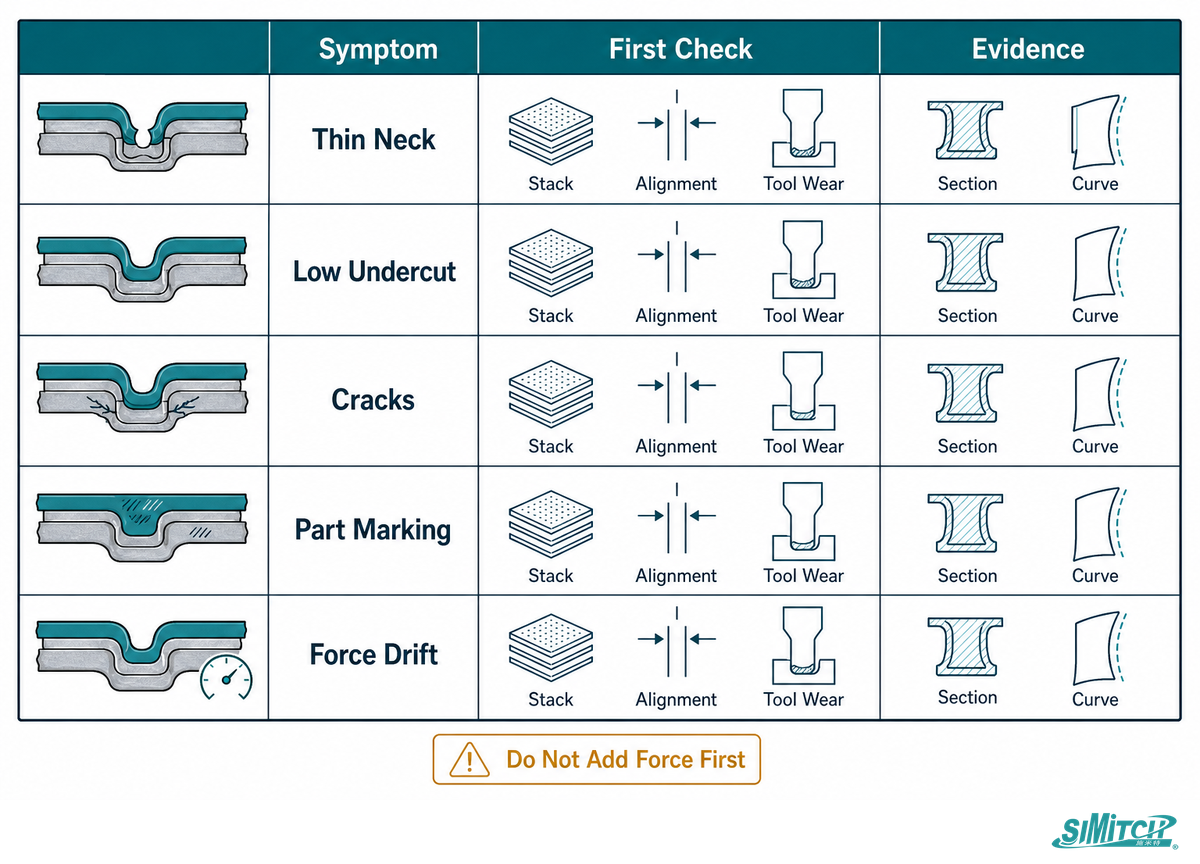
Clinching problems should be triaged from the observed symptom to the smallest defensible set of checks. Adding force first can worsen neck thinning, marking, distortion, or tool damage. A force-curve alarm is useful containment evidence, but it does not identify the root cause without inspection and comparison data.
| Symptom | First checks | Evidence needed | Stop or escalate when |
|---|---|---|---|
| Visible crack | Material condition, punch radius, tool geometry, alignment | Section image and material record | Crack enters the accepted load path |
| Low interlock | Die depth, stroke, stack, tool wear, press deformation | Cross-section and curve comparison | Geometry misses the approved window |
| Excessive neck thinning | Tool geometry, material order, over-travel, lubrication | Measured neck and setup record | Cracking or unstable failure mode appears |
| Surface marking | Contact faces, debris, coating, support pressure | Marked-side photos and clean-tool trial | Cosmetic requirement is breached |
| Part distortion | Fixture support, joint sequence, reaction path | Datum measurements before and after | Assembly fit or sealing surface moves |
| Variable button | Stack fit-up, pressure or power stability, alignment | Run chart and incoming-material data | Variation exceeds the approved process window |
| Joint opens in test | Failure mode, interlock, test direction, sample preparation | Failed sample and test trace | Functional acceptance is missed |
| Tool pickup or wear | Surface contamination, coating transfer, cleaning, tool condition | Magnified tool inspection and cycle history | Geometry or surface damage becomes unstable |
| Force-curve drift | Tooling, alignment, material, contamination, utilities, sensors | Golden-run overlay and physical inspection | Cause cannot be isolated inside the reaction time |
One real-case study abstract on long-term clinching integrity highlights systematic maintenance and continuous follow-up. That supports a production plan with tool-life limits, inspection intervals, reference-part checks, maintenance ownership, and escalation rules. Its abstract does not expose a complete root-cause list, so the diagnostic table above also relies on separately reviewed press-influence and field sources.
Do
- Contain suspect output when a monitored signal moves outside the approved window.
- Compare tooling, alignment, material, utility, and sensor evidence before naming a cause.
- Keep a reference part and section schedule tied to the maintenance plan.
Don’t
- Raise force automatically when the joint changes.
- Treat a curve alarm as proof of tool wear.
- Release production after a cosmetic check alone.
What are the disadvantages of clinching?
Clinching needs access for matched tooling, sufficient material formability, reaction-force support, application-specific qualification, and ongoing tool/process control. It can also leave a visible button and may not suit joints that require disassembly, a separate fastener, one-sided access, or a service condition that the formed stack cannot meet.
Integration and Utility Requirements for Production Equipment

Production clinching equipment must be specified as an interface set, not only as a press. Freeze utilities, physical envelope, part flow, controls, fieldbus, sensors, data retention, changeover, maintenance access, guarding, and responsibility boundaries before layout release; otherwise late integration work can overturn the selected architecture.
| Interface | Freeze before design release | Acceptance evidence |
|---|---|---|
| Air or hydraulic service | Pressure/flow basis, quality, connection, isolation | Utility sheet and loaded test |
| Electrical power | Voltage, frequency, installed load, disconnect | Electrical drawings and site verification |
| Physical envelope | Frame, motion, service clearances, floor or support loads | Approved layout and access review |
| Part flow | Loading, unloading, datum, reject and buffer route | Cycle demonstration with representative parts |
| Controls and fieldbus | PLC ownership, handshake, tag map, recipes | Interface test and approved signal list |
| Quality data | Signals, limits, record key, storage and retention | Traceability challenge and record retrieval |
| Changeover | Tool, fixture, recipe, verification and authorization | Timed change plus first-off approval |
| Maintenance | Tool-life limits, access, spares, reference-part interval | Maintenance trial and escalation drill |
| Safeguarding | Hazard review, point-of-operation protection, safe loading, interlocks | Risk assessment and jurisdiction-specific sign-off |
OSHA’s mechanical-power-press eTool states that barrier guards must prevent access to the point-of-operation danger zone and describes behavior for interlocked guards under 29 CFR 1910.217. Treat that as a United States safety-design reference point. Final clinching architecture and installation jurisdiction determine which rules and conformity work apply.
Assembly-servo monitoring example, not a clinching-machine rating
Simitch’s BP precision assembly press page publishes six force classes: 10 kN, 30 kN, 60 kN, 100 kN, 150 kN, and 200 kN. It also lists 0.01 mm repeat positioning, 10 kHz acquisition, six fieldbus options, up to 5,000,000 curve points, and 100,000 stored records. These figures illustrate questions a buyer can ask about monitoring and retention; they aren’t clinching force ratings.
0.01 mmpublished repeat positioning
10 kHzpublished acquisition rate
5,000,000published curve-point capacity
Use the precision servo press monitoring options only as an attributed interface example. For a clinching project, request the signals, sampling behavior, data structure, acceptance logic, and retention that are actually available on the proposed machine.
The 12-Field Clinching RFQ Pack
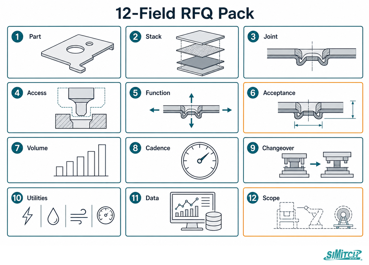
A usable clinching RFQ gives a supplier twelve connected inputs covering the part, stack, joint, access, function, acceptance, production, controls, and project scope. This pack reduces speculative model selection and makes omissions visible before tooling, fixtures, guarding, or integration commitments enter the quotation.
You can copy the following fields into a quote request. “To be confirmed by trial” is an acceptable entry when the owner and required evidence are named; a blank field is not.
RFQ checklist — copy these into your quote request:
| Field | Required input | Why it matters | How to verify |
|---|---|---|---|
| 1. Part drawing | Revision-controlled geometry and datums | Defines reach and support | Marked drawing plus representative part |
| 2. Material grade | Exact grade or certificate | Controls formability and evidence scope | Material certificate |
| 3. Thickness and order | Each layer in punch-to-die order | Changes flow and joint geometry | Stack record and measured samples |
| 4. Coating and surface | Coating, temper, lubricant, contamination limits | Affects forming and service exposure | Specification and production sample |
| 5. Joint map | Locations, count, sequence, witness side | Drives tooling and motion | Annotated CAD or drawing |
| 6. Access envelope | Approach, throat path, punch/die clearance | Can eliminate a frame | Clearance model and tool sketch |
| 7. Functional load | Static, cyclic, direction, environment | Defines the test plan | Product requirement |
| 8. Acceptance method | Geometry, load, failure mode, sampling | Defines release evidence | Signed approval plan |
| 9. Production cadence | Parts, joints, shifts, buffers | Shapes architecture and duty | Time study and capacity plan |
| 10. Changeover mix | Variants, frequency, authorization | Changes tooling and recipe scope | Variant matrix and trial |
| 11. Utilities and controls | Air, power, PLC, fieldbus, data retention | Defines interfaces | Site sheet and signal list |
| 12. Scope and site | Installation, guarding, training, spares, location | Prevents responsibility gaps | Responsibility matrix |
Send representative sheets and parts where practical, then ask for section images, applicable tensile-shear test results, process settings, curve samples, tooling assumptions, and a list of items excluded from the supplier’s scope. With those inputs prepared, compare Simitch’s clinching machine solution paths without turning a family name into a premature model commitment.
Review a real part with the right evidence
Before the meeting, have the drawing, stack, joint map, access envelope, acceptance plan, and service requirements ready.
When Clinching Is the Wrong Joining Method
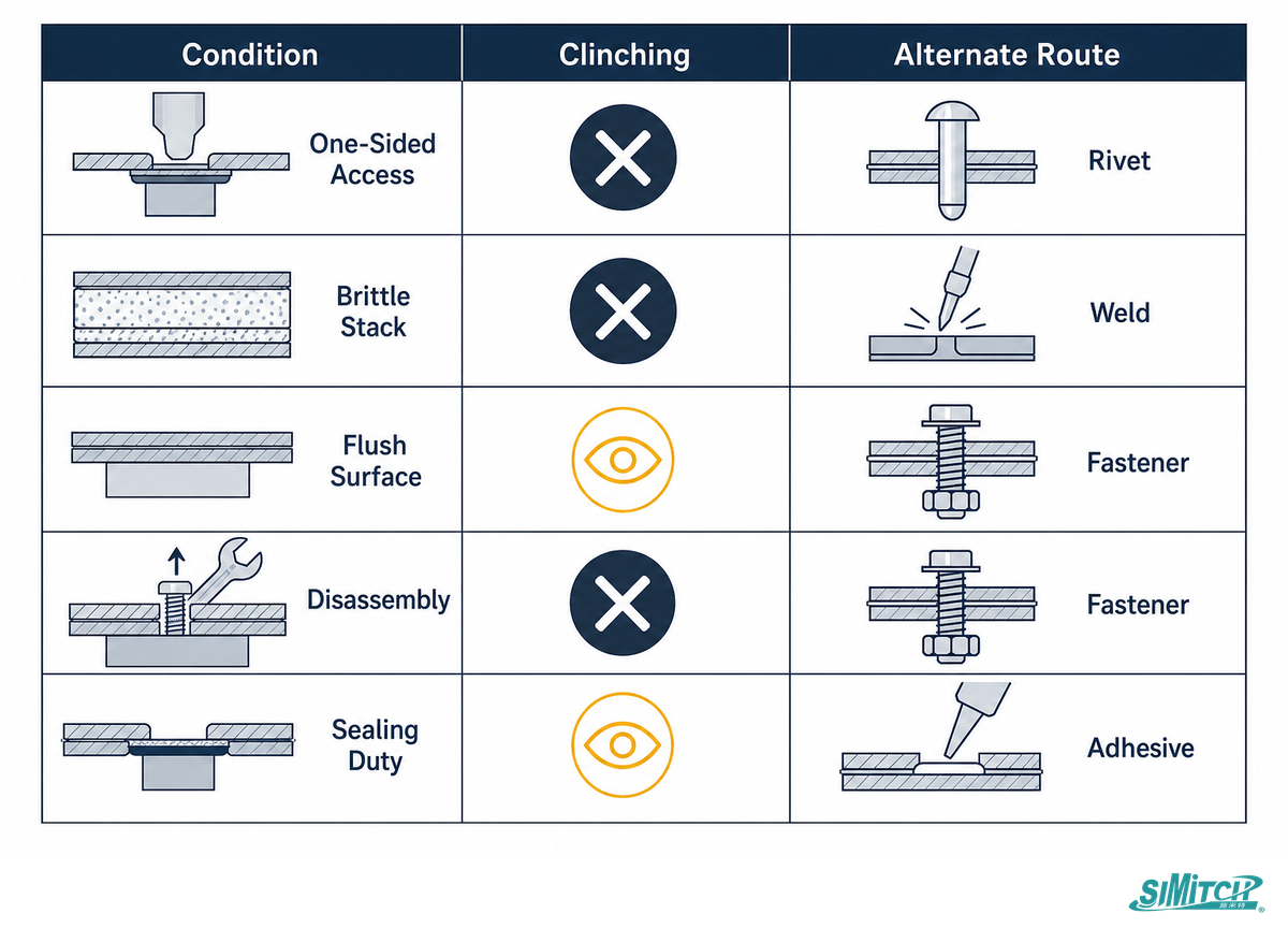
Clinching is the wrong method when the part cannot provide suitable two-sided access, the material stack cannot form an acceptable interlock, the visible button is prohibited, disassembly is required, or representative testing cannot demonstrate the needed static, fatigue, corrosion, sealing, or appearance performance.
Advantages worth testing
- No separate rivet in the formed joint
- No intentional weld-nugget melting
- Potential fit for coated or dissimilar stacks after qualification
- Visible and measurable formed geometry
Limitations that can stop the project
- Matched tooling access and reaction support
- Material formability and application-specific tooling
- Permanent button and possible witness marks
- Static, cyclic, environmental, and process-control evidence
| Constraint | Why clinching may not fit | Alternative to evaluate | Evidence needed |
|---|---|---|---|
| One-sided access only | Matched punch/die path is blocked | Self-piercing or blind fastening route | Access model and joint trial |
| Low ductility or cracking | Required material flow is unstable | Fastener, adhesive, weld, or modified clinch process | Section and performance tests |
| Separate fastener required | Fastener provides a specified function | SPR or conventional riveting | Functional requirement and comparison test |
| Heat is acceptable and weld criteria dominate | A welded joint may better match the established process | Spot welding | Weld qualification and total-process comparison |
| Disassembly required | Clinched joint is intended to be permanent | Threaded or serviceable fastener | Service procedure |
| Service-life evidence fails | Static formation cannot offset fatigue or environmental weakness | Redesign, hybrid joining, or another process | Representative fatigue/corrosion evidence |
DVS lists mechanical-joining guidance across fundamentals, design, metallic materials, quality assurance, testing, and work safety. An open review likewise ties joint quality to clinch type, equipment adjustment, and loading direction. Compare complete manufacturing and qualification routes rather than declaring clinching, riveting, adhesive joining, SPR, or spot welding universally superior.
Normalize marketplace language before comparing equipment
Search intent matters. Queries such as “clinching machines for sale,” “used clinching machines for sale,” and “new clinching machines” lead to inventory pages, not process guidance. An “air cam clinching machine” is an architecture label, while BTM and Norlok are brand searches; none of those labels proves that a machine fits a part. Keep transactional selection on the commercial solution page and use this guide to normalize the engineering evidence.
Commercial phrases such as “less expensive than conventional clinching” or “more expensive than conventional clinching machines” need a defined comparison boundary. Calling a machine an “economical method to clinch two” sheets, a “simple and economical method,” or the “simplest and most economical method” says nothing about tooling, changeover, utilities, rejects, qualification, or lifecycle cost.
Treat “28 to 14 gauge mild steel” as a vendor-specific claim, not a universal material window; even the phrase “14 gauge mild steel” omits grade, coating, stack order, and application load. A reliable equipment comparison asks the manufacturer to prove high-speed operation on representative parts instead of accepting “quality clinching” or “reliable” as evidence.
For custom clinching solutions, compare sheet metal joining and metal assembly requirements by channel geometry, fabrication sequence, throat depth, capacity, and duty. A “wide range” is not an acceptance criterion. Efficient production and efficiency claims belong in a timed sample run with an agreed reject definition and record-retention plan.
Frequently Asked Questions
What is the process of clinching sheet metal?
Short answer
Clinching places overlapping sheets between a punch and die, applies forming force, and displaces material to create a neck and mechanical undercut. Tool release leaves no separate rivet in the joint. After forming, inspect the button, section representative samples, and run the product owner’s specified performance tests. Those checks should cover the real stack, tooling, loading direction, and production window rather than accept one attractive sample from appearance alone.
What are the disadvantages of clinching?
Short answer
Clinching normally needs coordinated punch-side and die-side access, formable sheet material, reaction-force support, matched tooling, and application-specific qualification. Visible buttons may conflict with appearance requirements, while process drift requires tool and machine controls. Projects needing disassembly, one-sided access, a separate fastener, or an unproven fatigue and corrosion envelope should compare other joining methods before equipment is purchased.
How are clinching machines powered?
Short answer
Clinching equipment may use pneumatic, hydro-pneumatic, hydraulic, or servo-electric actuation. Drive choice changes utilities, motion control, force generation, feedback, and maintenance needs. Selection should start with the required process outcome and duty, then confirm the complete machine, frame, tooling, alignment, velocity, deformation, and material-stack window on representative parts before production approval.
Floor-mounted, desktop or portable clinchers?
Short answer
Choose by access and part presentation. Portable equipment follows the assembly; desktop or floor equipment requires the part to reach a stable station.
Can coated or dissimilar sheets be clinched?
Short answer
They may be, but “coated” or “dissimilar” isn’t enough information. Qualification should use the production grades, individual thicknesses in punch-to-die order, coating identity and thickness where known, temper, previous forming, surface condition, layer count, fit-up, and service environment. Review section geometry and functional tests on the real stack. Where cyclic loading, moisture, salt, cleaning chemistry, temperature, or galvanic interaction is relevant, add representative fatigue or environmental evidence. Specify which side may carry a witness mark, how coating transfer will be inspected, and what incoming-material change triggers a new trial. A first-day button can confirm formation, but it can’t approve a lifetime that was never tested.
Do you offer tooling and spare parts?
Buyer requirement
Don’t assume tooling and spares are included with any machine. Ask the supplier to identify the punch, die, blank holder, wear items, expected inspection method, recommended spare quantity, change procedure, lead time, drawing ownership, and whether replacement tooling requires a new first-off or sectioned-joint approval.
Conclusion: Approve the Evidence, Not the Label
Sound selection puts part data first, machine architecture second, and representative approval before production release. Clinching can be a clean, fast metal joining method, but only when access, stack, tooling, service load, safeguarding, maintenance, and ownership are treated as one system.
Key takeaway
Clinching becomes a defensible production choice only after the part, material stack, access path, acceptance evidence, controls, safety concept, and long-run maintenance plan agree.
Prepare the part data before choosing the press
Bring the drawing, stack record, joint map, service requirements, cadence, controls, and acceptance plan to the engineering discussion.
Related Articles and Planning Tools
How This Guide Was Framed
Simitch has worked in intelligent joining equipment since 2006, including clinching, riveting, SPAC, SPR, hydro-pneumatic boosters, and precision servo pressing for automotive, battery, photovoltaic, appliance, and HVAC applications. This guide converts public research and published equipment fields into a buyer-side validation and RFQ method; it does not replace a part trial or current model data. Reviewed by the Suzhou Simitch Machinery Co., Ltd. technical team.
References & Sources
- Review of the clinching process chain and operational properties — Journal of Advanced Joining Processes, 2022
- Robustness of clinching process and joint geometry — Journal of Advanced Joining Processes, 2021
- Three-layer aluminum-steel shear-clinching study — Journal of Advanced Joining Processes, 2026
- Pre-deformation and clinched-joint response study — Materials, 2026
- ISO 12996:2013, Mechanical joining — Destructive testing of joints — Specimen dimensions and test procedure for tensile shear testing of single joints — ISO
- ISO/TR 12998:2019, Mechanical joining — Guidelines for fatigue testing of joints — ISO
- Numerical investigation of pitting corrosion and high-cycle fatigue in clinched joints — Acta Mechanica, 2025
- Flexible self-pierce riveting and clinching with a single joining system using the same unified joining tools — ESAFORM 2024 conference paper
- Machine Guarding eTool: Press Barrier Guards — Occupational Safety and Health Administration
- Five Clinching Issues and How to Troubleshoot Them — Canadian Fabricating & Welding
- Mechanical clinching process and joint-quality review — open-access review, 2017
- Influence of the press system on clinched-joint formation — Key Engineering Materials, 2022
- Offset die and anvil access arrangement — US8650730B2
- Clinching punch taper disclosure — US10328481B2
- Long-term clinching process integrity case study — Journal of Materials Processing Technology, 2006
- DVS mechanical joining guidance catalogue — DVS
- Sheet Metal Clinching 101 — The Fabricator, 2024