Get in touch with Suzhou Simitch Machinery Co., Ltd Company

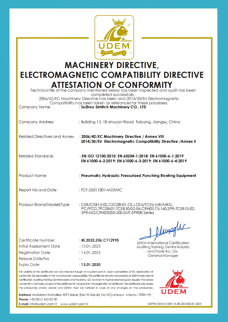
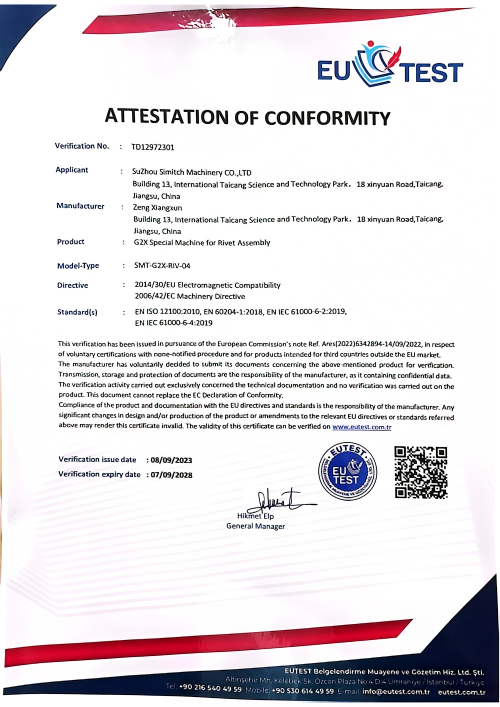
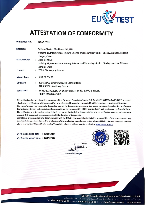
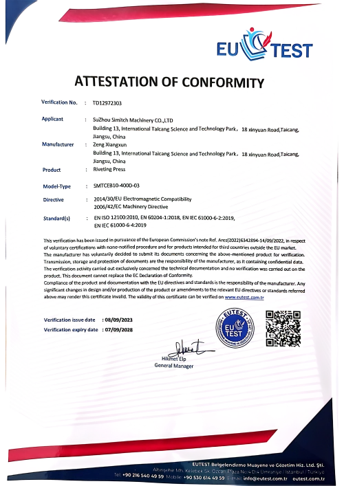
ISO Certified
Pneumatic & Servo Clinching Presses
Pneumatic & Servo Clinching Presses for Sheet Metal Joining
A sheet metal clinching machine must fit the part, form an acceptable clinch joint in the real material stack and support a safe production cell. Simitch starts with those inputs, then matches a documented pneumatic-hydraulic family or defines the missing requirements for a servo press.
Request a Clinching Press Quote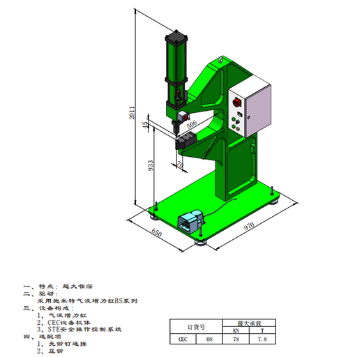
9
Documented press families
18.4–990 kN
Recorded fixed-press load range
45–75 kN
Suspended hand-tong range
5 gates
Before a recommendation
Five Gates Before a Clinching Press Recommendation
A machine can have enough nominal force yet fail at the neck or interlock because access, material flow and tooling set the real risk. An 18.4 kN bench press and a 990 kN floor press still need the same application proof; the honest version is that physics won’t yield to catalog tonnage.
01 Access
Confirm two-sided punch-and-die access, joint location, edge distance, fixture space and the loading path.
02 Material Stack
Record grade, condition, coating, each layer thickness, total thickness and planned punch-side orientation.
03 Frame
Fit the throat, work height, table, suspended tool or column opening around the part and fixture envelope.
04 Drive & Data
Define output force, stroke, air or power supply, control sequence, monitoring need and production interface.
05 Trial Approval
Agree on joint geometry, destructive checks, load tests, routine inspection and the evidence needed for release.
Recorded Product Data
Family names, rated loads, source-drawing dimensions and listed options are shown in the product section.
Your Application Inputs
Material condition, coating, layer order, access envelope, joint loading and output targets come from your part.
Trial Results
Formed geometry, test loads, section results and the agreed inspection window come from samples, not a catalog.
Engineering Confirmation
Tooling, final press model, servo hardware, controls, interfaces, guarding and commercial scope need project review.
“A rated load is a machine boundary, not a joint approval. We recommend the press only after the part, stack, tooling route and acceptance evidence line up.”
Simitch Application Engineering Principle
Start With the Rejection Conditions
No practical two-sided access, a brittle or unproven stack, or no reliable inspection route? Those are reasons to pause before discussing tonnage, because a larger press doesn’t fix the wrong joining route.
Define the Material Stack and Clinch Joint Acceptance Window
Peer-reviewed reference: Review of clinch-joint geometry, tooling and material behavior.
Poor fit-up and alignment can create inconsistent clinch geometry even when machine settings are unchanged. That risk persists because an 18.4 kN or 990 kN rating can’t reveal neck thickness, interlock or bottom thickness in your fixture and production material.
Information to attach to a sample request
- Material grade and condition for every layer
- Individual and total sheet thickness
- Stainless steel, mild steel, aluminum, copper or mixed stack
- Galvanized, painted or other coating system
- Proposed punch side and die side
- Joint edge distance and surrounding formed features
- Peel, shear, tension or service-load direction
- Appearance limits and allowed surface marks
- A good-looking button is not the release criterion
Early destructive tests can establish whether the tool and stack produce a usable joint, while routine production may use agreed visual or dimensional checks. Monitoring helps detect process change, but research also warns that some non-destructive indicators aren’t conclusive on their own.
| Decision Stage | Evidence to Review | What it Answers | Boundary |
|---|---|---|---|
| Feasibility | Access study, coupons, material certificates | Can the tool reach and form the stack? | Not proof of service strength |
| Tool trial | Neck, interlock, bottom thickness, visible defects | Is the joint geometry inside the agreed window? | Window is stack- and tool-specific |
| Mechanical approval | Shear, peel, tensile or part-level test | Does the joint meet the buyer’s load target? | Test method and sampling must be agreed |
| Routine control | Visual checks, dimensions, force-displacement window if specified | Has the process moved away from the approved state? | Does not replace the original validation plan |
Punch-side orientation is a trial input
Material strength, thickness and coating can change how the joint form. Treat any simple “harder sheet on this side” rule as a starting hypothesis, then approve the orientation from your samples.
Choose a Frame Around the Part, Not the Catalog
Hazard-planning reference: OSHA hydraulic press eTool.
A deep throat doesn’t solve a joint that lacks punch-and-die access from both sides, and the wrong frame create a fixture or operator risk. CEC’s 506 mm throat and 933 mm work height help define space, whereas Simitch still has to confirm the full production envelope.
Compare Pneumatic-Hydraulic and Servo Clinching Routes
Monitoring references: ISIJ International on observing clinching process conditions and a peer-reviewed clinching review. This category-level evidence does not verify a Simitch servo model.
Force-displacement monitoring is a hardware and measurement-chain decision, not a label for every 78–990 kN press. Buyers comparing a pneumatic press machine with a servo press first need to define the production motion, sensing and control requirements.
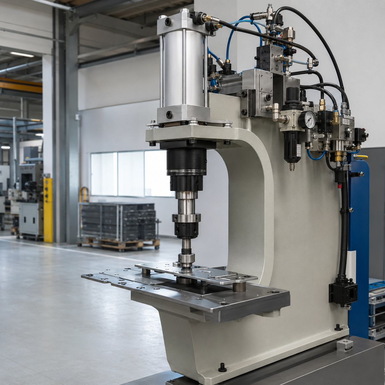
Documented pneumatic-hydraulic route
- Nine recorded families with rated load and frame data
- Compressed-air input with a pneumatic-hydraulic power stroke
- C-frame, deep-throat, floor, suspended and column forms
- PC source sheet lists optional force-displacement monitoring
Engineering-defined servo route
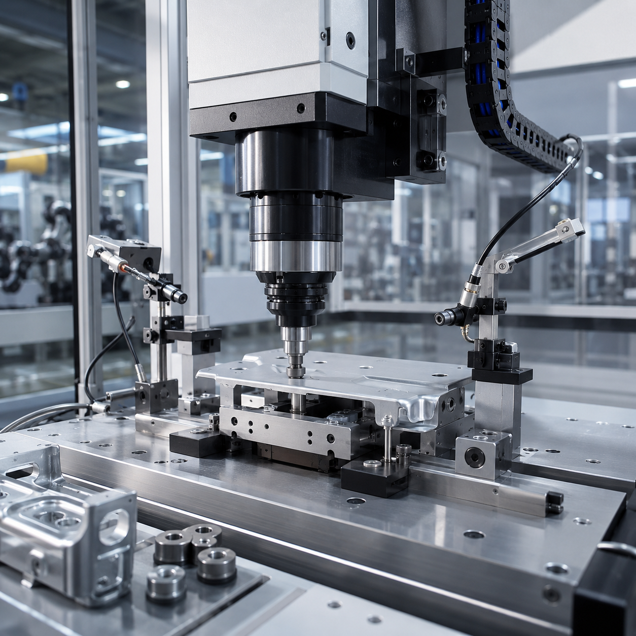
- Specify press force and full motion or stroke profile
- Define servo motor, load cell and position feedback needs
- Set force control, recipe, traceability and real-time data boundaries
- Confirm interfaces, calibration plan and acceptance method
When measured motion may matter
Academic work shows that force-versus-travel measurement and monitoring windows can reveal condition changes in clinching experiments. That evidence supports asking whether a line need programmed motion or process monitoring; it doesn’t prove a Simitch servo model, accuracy, repeatability or energy result.
| Decision item | Pneumatic-hydraulic project | Servo project |
|---|---|---|
| Current product evidence | Loads, dimensions and options for nine families | No model-specific data supplied |
| Drive definition | Air supply, approach, power stroke, return and pressure setting | Motor, drive, motion profile, force and position loop |
| Measurement | Optional only where the selected model and scope support it | Sensor, sampling, limits, storage and calibration must be specified |
| Selection proof | Part fit plus sample and acceptance evidence | The same evidence, plus verified controller and measurement-chain data |
Do not buy the keyword
“Servo press” can describe very different pressing and joining systems. Buy the motion, sensing, acceptance and interface functions your clinching process needs, not an unverified assumption that electric drive is always better. That trade-off belongs in the project definition, not in an unsupported energy or ROI claim.
Simitch Pneumatic-Hydraulic Clinching Press Families
Evidence Boundary: model values below come from customer-supplied sheets. See peer-reviewed clinching process context for category terminology, not Simitch specifications.
A clinching machine for sheet metal can still be the wrong buy when a 45 kN suspended tool or 990 kN floor press doesn’t fit the fixture. Simitch publishes 9 families and 36 parameter rows so frame and tooling risk remain visible, rather than being reduced to a generic list of hydro pneumatic press manufacturers.
Specification Status: values are transcribed from the supplied Simitch sheets and must be confirmed in the issued engineering drawing and quotation before order.
[ CRH03 | CEC | CEB | TCEU | CEU | CEJ | PC | MA | MB ]
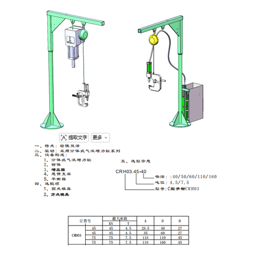
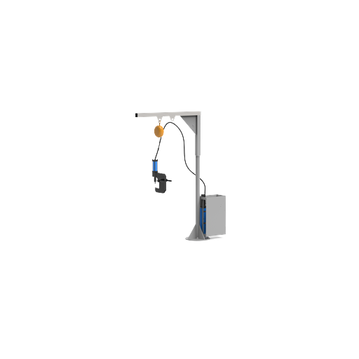
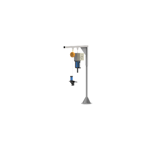
CRH03 Suspended Hand-Tong Clinching Press
The CRH03 clinching tool goes to the work piece instead of taking the large component into a fixed frame. It notes 45 and 75 kN load classes with the option of various throat / reach lengths.
- Flexible suspended arrangement
- Split pneumatic-hydraulic booster-cylinder drive
- Optional round-point and square-point tooling
- Recorded reach options: 40, 50, 60, 110 and 160 mm
| Order No. | Max Load | Load Class | A | D | H |
|---|---|---|---|---|---|
| 45 | 45 kN | 4.5 t | 28.5 mm | 40 mm | 27 mm |
| 45 | 45 kN | 4.5 t | 35 mm | 60 mm | 27 mm |
| 75 | 75 kN | 7.5 t | 118 mm | 110 mm | 45 mm |
| 75 | 75 kN | 7.5 t | 118 mm | 160 mm | 45 mm |
Click Image to Switch
CEC Universal Clinching Press
CEC is the documented fixed-frame option with a 506 mm throat and a working height of 933 mm. It’s a 78 kN pneumatic-hydraulic press machine in the supplied sheet.
- Extra-deep throat
- Pneumatic-hydraulic booster-cylinder drive
- CEC equipment frame
- Source sheet lists an STE safety operating control system; final safety functions require machine review
| Order No. | Max Load | Load Class | Overall Height | Working Height | Throat | Base L × W |
|---|---|---|---|---|---|---|
| 08 | 78 kN | 7.8 t | 2011 mm | 933 mm | 506 mm | 970 × 650 mm |
A 45 mm detail dimension is also recorded; confirm its reference points on the engineering drawing.
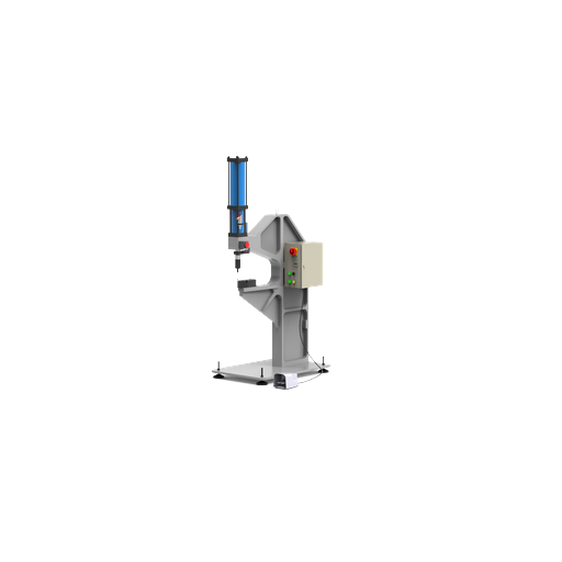
CEB C-Frame Bench-Top Clinching Press
CEB covers six recorded sizes from 18.4 to 283.6 kN. This C-frame bench form suits parts supported at table height, subject to the A, H envelope shown in the source drawing.
- Bench-top C-frame form
- Integrated pneumatic-hydraulic booster cylinder
- Model pattern: CEB load class with 02, 01 or 00 tooling arrangement
- T-Slot field retained exactly from the supplied parameters
| Order | Max Load | A | B | C | D | E | H | T-Slot |
|---|---|---|---|---|---|---|---|---|
| 02 | 18.4 kN / 1.84 t | 400 | 400 | 220 | 160 | 100 | 300 | 10 |
| 04 | 38.2 kN / 3.82 t | 450 | 450 | 220 | 160 | 100 | 300 | 12 |
| 08 | 78 kN / 7.8 t | 450 | 480 | 250 | 160 | 120 | 320 | 12 |
| 15 | 134 kN / 13.4 t | 500 | 600 | 314 | 200 | 150 | 350 | 14 |
| 20 | 184 kN / 18.4 t | 500 | 660 | 450 | 300 | 200 | 350 | 18 |
| 30 | 283.6 kN / 28.36 t | 550 | 660 | 450 | 300 | 200 | 350 | 18 |
A, H entries are millimeters; the source sheet doesn’t define every letter in English.
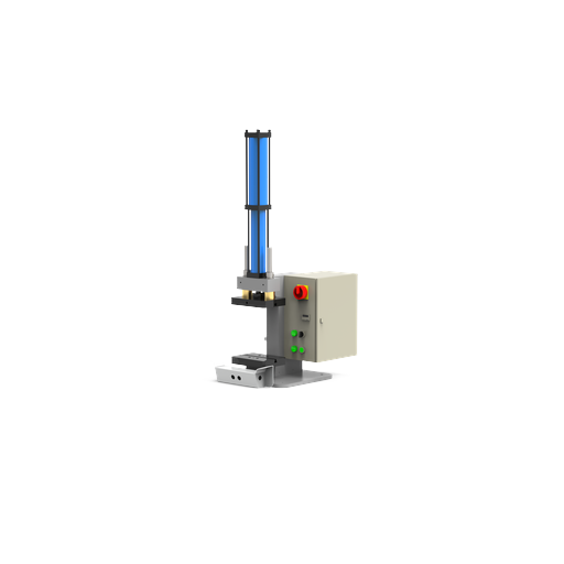
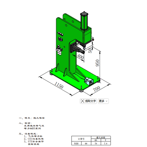
TCEU Air-Duct Clinching Equipment
TCEU is the named air-duct arrangement in the customer sheet. Its documented boundary is 78 kN with a 400 mm throat; material, sheet thickness and production rate still need a sample-based review.
- Extra-deep throat arrangement
- Pneumatic-hydraulic booster-cylinder drive
- CEC equipment frame
- Source sheet lists STE safety operating control
| Order No. | Max Load | Load Class | Overall Height | Throat | Detail | Base L × W |
|---|---|---|---|---|---|---|
| 08 | 78 kN | 7.8 t | 950 mm | 400 mm | 50 mm | 1150 × 700 mm |
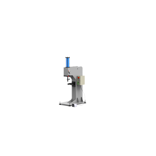
CEU Universal Floor Clinching Press
CEU provides 78 and 134 kN recorded load classes in a floor-standing universal frame. Both rows retain the 1100 mm C field, 500 mm D field and 60 mm H field from the source drawing.
- Extra-deep throat form
- Pneumatic-hydraulic booster-cylinder drive
- CEC equipment frame
- Final point-of-operation protection is defined for the real loading arrangement
| Order | Max Load | A | B | C | D | H |
|---|---|---|---|---|---|---|
| 08 | 78 kN / 7.8 t | 935 mm | 700 mm | 1100 mm | 500 mm | 60 mm |
| 15 | 134 kN / 13.4 t | 1045 mm | 800 mm | 1100 mm | 500 mm | 60 mm |
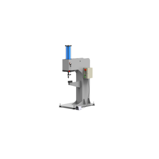
CEJ C-Frame Floor Clinching Press
CEJ records a 134 kN floor C-frame model and a worktable that may be adapted to the customer’s product. That adaptation still begins with the part and fixture envelope, not the rated force.
- Customer-product worktable option
- Pneumatic-hydraulic booster-cylinder drive
- CEJ equipment frame
- Source sheet lists STE safety operating control
| Order | Max Load | A | B | C | D | H |
|---|---|---|---|---|---|---|
| 15 | 134 kN / 13.4 t | 1100 mm | 1050 mm | 890 mm | 130 mm | 260 mm |
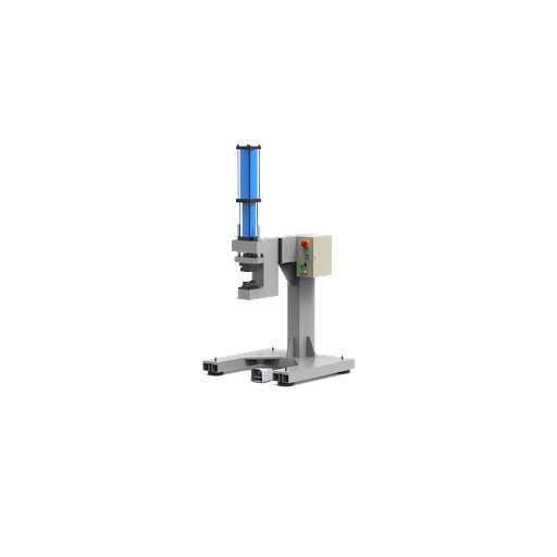
PC Floor-Standing Clinching Press
PC spans seven supplied load classes from 78 to 990 kN. The source sheet also lists optional guarding and optional force-displacement monitoring, which must be scoped as actual hardware, controls and acceptance logic for the chosen press.
- Machine size may be adapted to the customer’s product
- Pneumatic-hydraulic booster cylinder and PC frame
- 04 four-guide-column, 02 two-guide-column or 00 no-guide-column model pattern
- Optional guarding and force-displacement monitoring
| Order | Max Load | A | B | C | D | H | T-Slot |
|---|---|---|---|---|---|---|---|
| 08 | 78 kN / 7.8 t | 900 | 600 | 750 | 205 | 280 | 12 |
| 15 | 134 kN / 13.4 t | 900 | 660 | 750 | 225 | 350 | 14 |
| 20 | 184 kN / 18.4 t | 1200 | 750 | 750 | 255 | 400 | 18 |
| 30 | 283.6 kN / 28.36 t | 1300 | 800 | 750 | 255 | 450 | 18 |
| 50 | 477.6 kN / 47.76 t | 1400 | 1000 | 750 | 255 | 550 | 18 |
| 75 | 735.7 kN / 73.57 t | 1500 | 1200 | 750 | 255 | 550 | 18 |
| 100 | 990 kN / 99 t | 1600 | 1200 | 750 | 255 | 550 | 18 |
A, H values are in millimeters. Monitoring isn’t presented as standard equipment or as proof of joint acceptance.
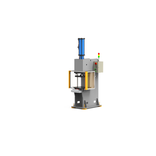
MA Four-Column Clinching Press
MA uses a four-column frame and seven supplied load rows. The source sheet lists optional guarding plus a UM die base or welded base, while final open height and die space must be checked against the part.
- Machine size may be adapted to the customer’s product
- Pneumatic-hydraulic booster-cylinder drive
- 04 four-guide-column or 00 no-guide-column model pattern
- Optional UM die base or welded base
| Order | Max Load | A | B | C | D | E | H | T-Slot |
|---|---|---|---|---|---|---|---|---|
| 04 | 38.2 kN / 3.82 t | 790 | 810 | 775 | 200 | 160 | 280 | 10 |
| 08 | 78 kN / 7.8 t | 790 | 810 | 775 | 310 | 200 | 350 | 12 |
| 15 | 134 kN / 13.4 t | 790 | 810 | 775 | 350 | 250 | 380 | 14 |
| 20 | 184 kN / 18.4 t | 790 | 810 | 775 | 360 | 260 | 400 | 18 |
| 30 | 283.6 kN / 28.36 t | 790 | 810 | 775 | 360 | 260 | 400 | 18 |
| 50 | 477.6 kN / 47.76 t | 1000 | 810 | 775 | 460 | 260 | 550 | 18 |
| 75 | 735.7 kN / 73.57 t | 1000 | 810 | 775 | 500 | 280 | 350 | 18 |
Check the MA 75 H field: The source row prints H as 350 mm, lower than the 50 row’s 550 mm. It’s reproduced here without correction and needs engineering confirmation before it supports a selection.
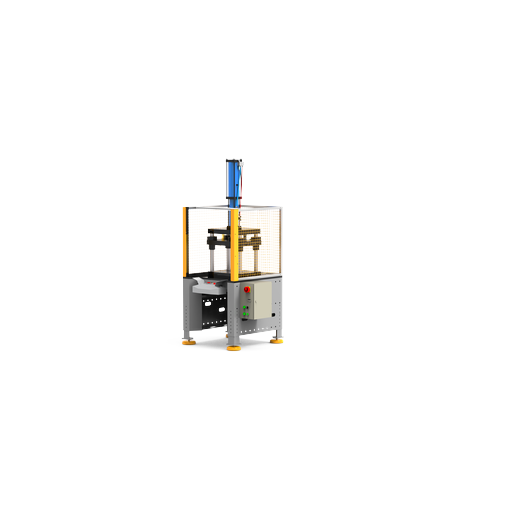
MB Double-Column Clinching Press
MB shares the 38.2 to 735.7 kN recorded range while using a double-column frame. The D and E fields increase across several rows, so both directions need to be mapped to the workpiece and die concept.
- Machine size may be adapted to the customer’s product
- Pneumatic-hydraulic booster-cylinder drive
- 04 double-guide-column or 00 no-guide-column model pattern
- Optional guarding, UM die base or welded base
| Order | Max Load | A | B | C | D | E | H | T-Slot |
|---|---|---|---|---|---|---|---|---|
| 04 | 38.2 kN / 3.82 t | 790 | 810 | 775 | 270 | 300 | 280 | 10 |
| 08 | 78 kN / 7.8 t | 790 | 810 | 775 | 290 | 300 | 350 | 12 |
| 15 | 134 kN / 13.4 t | 790 | 810 | 775 | 300 | 350 | 380 | 14 |
| 20 | 184 kN / 18.4 t | 790 | 810 | 775 | 360 | 350 | 400 | 18 |
| 30 | 283.6 kN / 28.36 t | 790 | 810 | 775 | 360 | 350 | 400 | 18 |
| 50 | 477.6 kN / 47.76 t | 790 | 810 | 775 | 460 | 450 | 550 | 18 |
| 75 | 735.7 kN / 73.57 t | 790 | 810 | 775 | 500 | 500 | 350 | 18 |
Check the MB 75 H field: The supplied row prints H as 350 mm after the 50 row lists 550 mm. Keep that value provisional until the drawing and machine proposal agree.
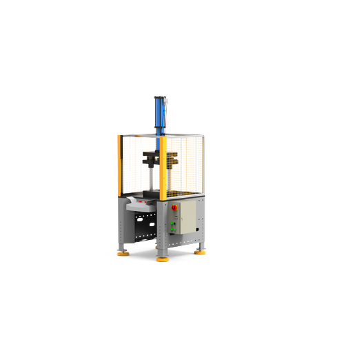
Specify Controls, Monitoring and Machine-Specific Safeguarding
Regulatory baseline: OSHA 29 CFR 1910.212. It does not certify a delivered machine or cell.
Point-of-operation and material-handling hazards change with loading, initiation and guarding because the operator and fixture share one opening. OSHA 29 CFR 1910.212 gives the baseline, but a control-system name doesn’t prove that a 78–990 kN cell is safe.
Initiation and cycle control
- Foot control, two-hand initiation, automatic cycle or external command
- Single-cycle, setup and maintenance states
- Approach stroke, power stroke, hold and return sequence
- Stop, reset and restart behavior after interruption
Access and material handling
- Front, side and rear access to the point of operation
- Manual loading, fixture loading, conveyor or robot feed
- Suspension balancer, clamps and part-support devices
- Scrap, rejected part and tool-change paths
Risk-reduction architecture
- Fixed or movable barriers where the layout permits
- Interlocks, two-hand devices or electronic safety devices as assessed
- Emergency-stop placement and isolation provisions
- Interfaces with upstream and downstream equipment
Measurement chain
- Sensor type, range and mounting location
- Force and displacement sampling plus decision window
- Recipe control, user access and real-time data needs
- Calibration, storage and reaction to an out-of-window cycle
A control-system name is not a safety conclusion
Several supplied sheets list an STE safety operating control system, and some families list guarding as an option. The buyer and machine supplier still need to confirm the delivered functions, risk assessment, validation evidence and local legal duties for the final cell.
Monitoring has a narrower job
A force-displacement trace may flag a changed process condition when the sensor, limits and reference window are valid. It can’t by itself prove joint strength, replace material-stack trials or make every cycle acceptable without a defined reaction plan.
Why Simitch for Clinching and Precision Pressing
Company and project references: Simitch About page and ISO 10006:2017 project-quality guidance. Broader development history below remains attributed to Simitch.
Supplier proof matters on a new site because unverified industry claims create risk for production and procurement. Simitch states that it began in 2006 and now presents 9 product families with 36 parameter rows; patent and certificate claims remain outside this page until public evidence is available.
Est. 2006
Company-Provided History
9 Families
Image And Parameter Records
36 Rows
Published With Source Boundaries
Trial-Gated
Part Evidence Before Release
A Practical Project Path
| Stage | Working Output | Decision |
|---|---|---|
| Part review | Joint map, access envelope and fixture constraints | Is two-sided clinching access practical? |
| Joinability review | Material-stack risk list and sample plan | Can a useful trial be designed? |
| Frame & drive selection | Shortlist with missing inputs stated | Documented air-over-oil family or servo definition? |
| Tooling & trial plan | Punch and die concept plus acceptance checks | What evidence will approve the joint? |
| Equipment build | Agreed machine, controls and cell interfaces | Does the delivered scope match the approved proposal? |
| Handover & support | Agreed records, training, spares and support boundary | Can production own and maintain the process? |
×
![Enlarged View]()
Pneumatic & Servo Clinching Press Engineering Tools
01
Clinching Press Family Selector
Screen the nine documented Simitch pneumatic-hydraulic families by work format, load boundary and access preference. The result narrows an engineering conversation; it does not approve a material stack or tooling design.
Access Tool
02
Compare Simitch Clinching Press Families
Place two documented pneumatic-hydraulic families side by side. The comparison keeps frame, load range, source-sheet options and open questions visible instead of treating the largest rating as the automatic winner.
Access Tool
03
Five-Gate RFQ Readiness Checker
Estimate whether your inquiry contains enough information for a useful clinching-press review. The score measures input completeness, not joint feasibility, safety compliance or purchase approval.
Access Tool
Frequently Asked Questions for Clinching Equipment Buyers
What is the difference between a sheet metal clinching machine and a sheet metal clinching hand tool?
A production clinching machine may be bench-mounted, floor-standing, column-guided or suspended, with a defined frame, drive and control system. A retail hand tool is a different buying category; CRH03 is an industrial suspended hand-tong press family, not a manual pair of pliers.
Why does material stack order matter in clinching?
Punch-side and die-side materials don’t deform in the same way. Grade, condition, coating and thickness can change the neck and interlock, so orientation belongs in the sample plan.
How do coatings and different sheet strengths affect a clinch trial?
Coatings may change friction, surface marking or local cracking, while strength mismatch changes material flow. Send real production material rather than relying only on nominal thickness.
How do I choose a suspended, bench, floor or column press?
Start with the part and fixture envelope. Suspended tooling reaches large or awkward assemblies; bench and C-frame machines suit accessible joint locations; column frames serve layouts that need a guided open work area. The final choice also depends on loading, safeguards and trial results.
What is the difference between pneumatic, hydro-pneumatic and servo clinching routes?
A pneumatic press uses compressed-air force directly, while a hydro-pneumatic press uses air with a hydraulic power stage to raise output force. A servo press uses an electric motor and control system for defined motion; Simitch servo details must be specified and verified for each project.
Is a Simitch servo clinching press model documented on this page?
No. Only pneumatic-hydraulic families are documented in the supplied product sheets, so any servo model, specification, controller or availability must be provided and verified in writing for a project.
What press force do I need for my sheet-metal joint?
There’s no safe answer from total thickness alone. Tool geometry, material stack, joint target and press losses all matter, so rated output force is a machine boundary and a trial confirm the application.
Can Simitch customize the worktable, frame or guarding?
The CEJ sheet lists a customer-product worktable option, while PC, MA and MB sheets state that machine size may be adapted; PC, MA and MB also list guarding as optional. The exact changes and the resulting risk control need a written machine proposal.
When is force-displacement monitoring relevant?
Consider it when the process need a measured signature, an out-of-window reaction, stored cycle data or tighter change detection. The PC sheet lists it as an option, but sensor range, sampling, decision logic and calibration still need definition.
What should I send for a sample trial and quotation?
Send production-grade sheets, layer order, coatings, a part drawing, joint locations, service-load direction and acceptance targets. Add volume, loading method, utilities, destination and control interfaces if they’re known.
What affects the total quote scope of a clinching press?
Machine size is only one line. Tooling, fixtures, sample work, monitoring, guarding, automation interfaces, training, spares, technical records and freight can all change the scope, so ask for them separately.
How are tooling, spare parts, training and technical documents handled?
They should be named in the proposal with quantities, formats, language and delivery boundary. No standard Simitch package is assumed on this page.
When should Simitch decline or redirect an application?
A different joining method should be considered when two-sided access is impossible, the stack can’t form an acceptable joint, the service requirement can’t be validated, or the required cell can’t be safeguarded as designed. Saying no early is better than sizing a press around a process that hasn’t passed feasibility.