Portable & Handheld Clinching Machines for Sheet Metal Assembly

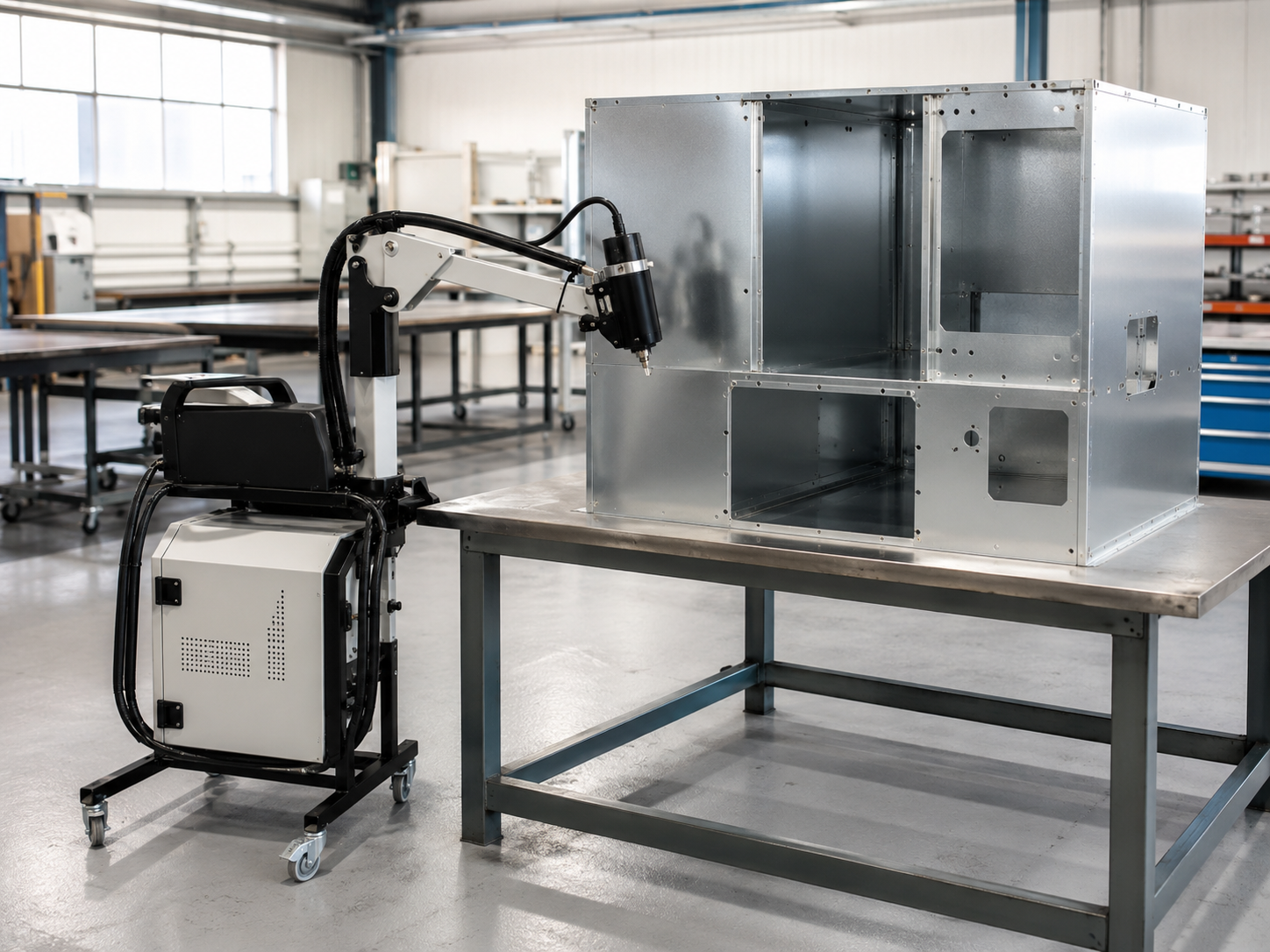
Large parts and formed profiles can be difficult to move into a fixed press. A handheld clinching tool brings punch-and-die joining to the workpiece, while Simitch reviews joint access, material stack and acceptance criteria before suggesting a C-type or X-type configuration.

Request a Portable Clinching Quote
Industrial sheet-metal joining equipment, not a clipper, stapler, upholstery tool or general-purpose plier.
Portable and Handheld Clinching Machines for Sheet Metal Assembly

Choose C-Type or X-Type

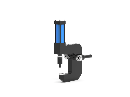
Simitch C-Type Portable Configuration

C-Type Portable Configuration

  • Shortlisted from measured reach, opening and obstruction data.
  • Final force, utility and tooling depend on the material stack you propose.
  • Production recommendation follows a sample-joint review.
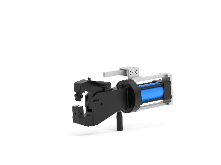
Simitch X-Type Portable Configuration

X-Type Portable Configuration

  • Shortlisted from approach direction, profile geometry and surrounding clearance.
  • Frame configuration isn’t treated as proof of load capacity or material condition.
  • Tooling and acceptance criteria are established on the actual part.
2

customer-supplied portable configuration renders

2 sides

required for punch-and-die access at the joint

0

added rivets or screws in a clinched joint

3 layers

access, joint mechanics and production control

4 states

confirmed, buyer input, sample output or not supplied

Since 2006

Simitch sheet-metal connection machinery experience

Drawing-led

configuration shortlist before commercial scope

Sample-led

joint approval before production recommendation

Portable Clinching Where the Part Cannot Move to a Fixed Press

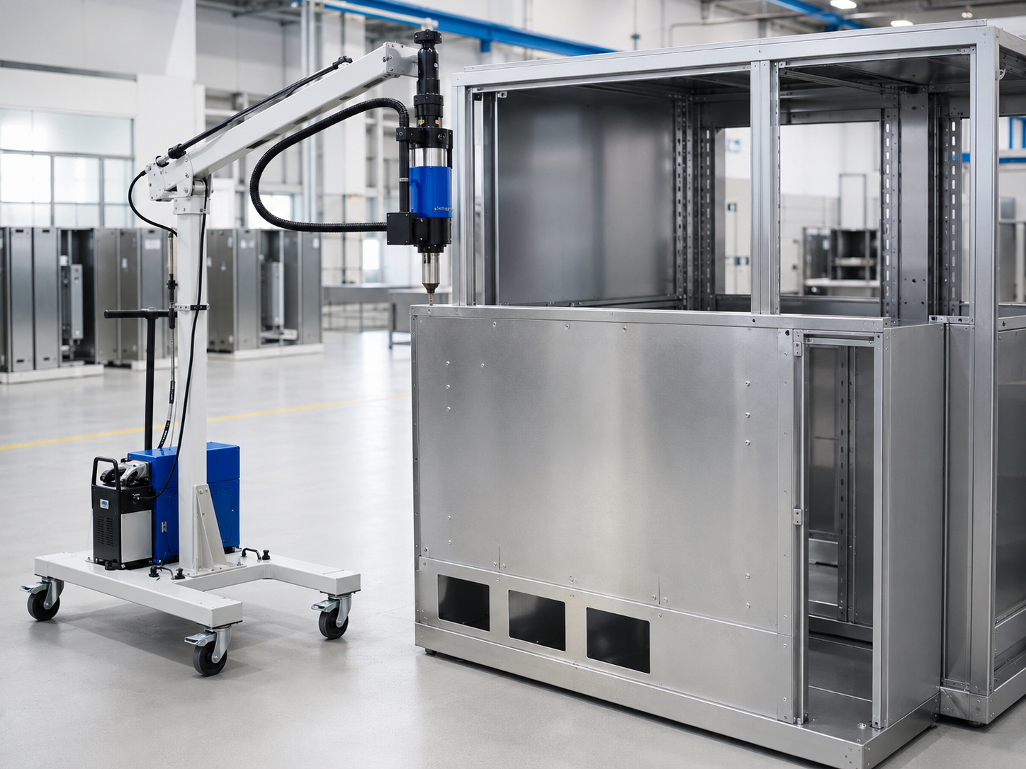
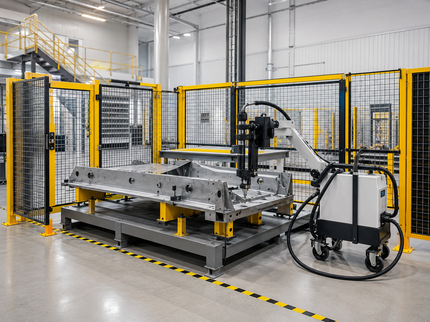
Large panels, constructed frames and assembled enclosures often introduce an access problem before a joining problem. Portable clinching machines take the tool to the joint while leaving the part supported at its workplace.

Portable Clinching Machine Tooling
  • Punch-and-die tooling must reach opposite sides of the planned joint configuration.
  • Throat opening, reach distance, approach angle and nearby returns must be established from the part drawing.
  • Hoses, wires, suspension and operator access must be considered in the real work area.

One common failure: the frame can look portable but still fail when two-sided tooling can’t reach the joint. An honest trade-off is that Simitch engineering must review the tool path and part drawing before a portable outline becomes a credible selection.

Request a Simitch engineering access check with the front, side and section views.
  • HVAC duct sections and formed fittings
  • Electrical enclosures, cabinets and boxes
  • Appliance and equipment panels
  • Channels, frames and large assemblies
  • Material compatibility or total thickness
  • Required forming force or tool life
  • Joint strength in the customer’s load direction
  • Simitch model fit without drawing and sample review
Common review candidates for portable clinching
What the category name does not prove

A joint-location or process change is appropriate whenever two-sided access can’t be created without risk to personnel or equipment.

Trade-press guidance treats two-sided access and throat depth as physical limits rather than setup details. Refer to The Fabricator’s sheet metal clinching overview for the access principle.

Choose a C-Type or X-Type Handheld Clinching Configuration

Frame geometry creates access; it isn’t proof of load capacity, material qualification or joint strength. Selection begins with the part and moves through material behavior, punch-and-die geometry and the load used for approval.

Confirm two-sided reach
STEP 1
STEP 1

Confirm two-sided reach

Mark the joint center, tool approach and obstructions on front, side and section views. If both tooling sides can’t reach, move the joint or review another process.

Measure the access envelope
STEP 2
STEP 2

Measure the access envelope

Record required reach, opening, edge distance, flange depth and clearance around the linkage. Compare those dimensions with controlled Simitch drawings, not with a product photograph.

Define the sheet stack
STEP 3
STEP 3

Define the sheet stack

List material grade, coating, individual thickness, total thickness and which layer sits on the punch side. A 2021 study found that sheet stiffness and order changed cross-tension and shear performance in different ways.

Approve the joint, then the machine
STEP 4
STEP 4

Approve the joint, then the machine

Specify the load direction, section measurements and failure evidence needed for approval. Configuration advances only after the sample plan matches the buyer’s acceptance criteria.

Why sheet order belongs in the inquiry

Changing which sheet sits on the punch side can alter joint strength, and the preferred sheet order may reverse for different load modes. Its publisher abstract describes this trade-off between cross-tension and shear behavior.

  • Review the material and thickness configuration study.
  • Ask Simitch engineering to record the intended punch-side sheet and load direction.
  • Treat C-type and X-type as access candidates until the part drawing and sample resolve these risks.
Decision input C-type candidate X-type candidate Engineering review route
Customer-supplied product renders 1 render 1 render 0 performance conclusions from image alone
Minimum drawing views requested 3 views 3 views Front + side + joint section
Access dimensions requested 2 core measures 2 core measures Required reach + required opening
Material fields requested 3 fields 3 fields Grade + individual thickness + total stack
Joint-validation outputs 4 outputs 4 outputs Section + tensile-shear + peel/cross-tension + failure mode
When the drawing is inconclusive Hold selection Hold selection Custom tooling, different joint location or another process

Keep frame choice separate from joint approval

This shortlist records what each frame can reach without implying that frame shape proves strength. Unlike a photo-led choice, it keeps material, tooling and sample evidence attached to the decision.

Request a C-type or X-type drawing review from Simitch

How the Clinch Joint Forms Without Rivets or Welding

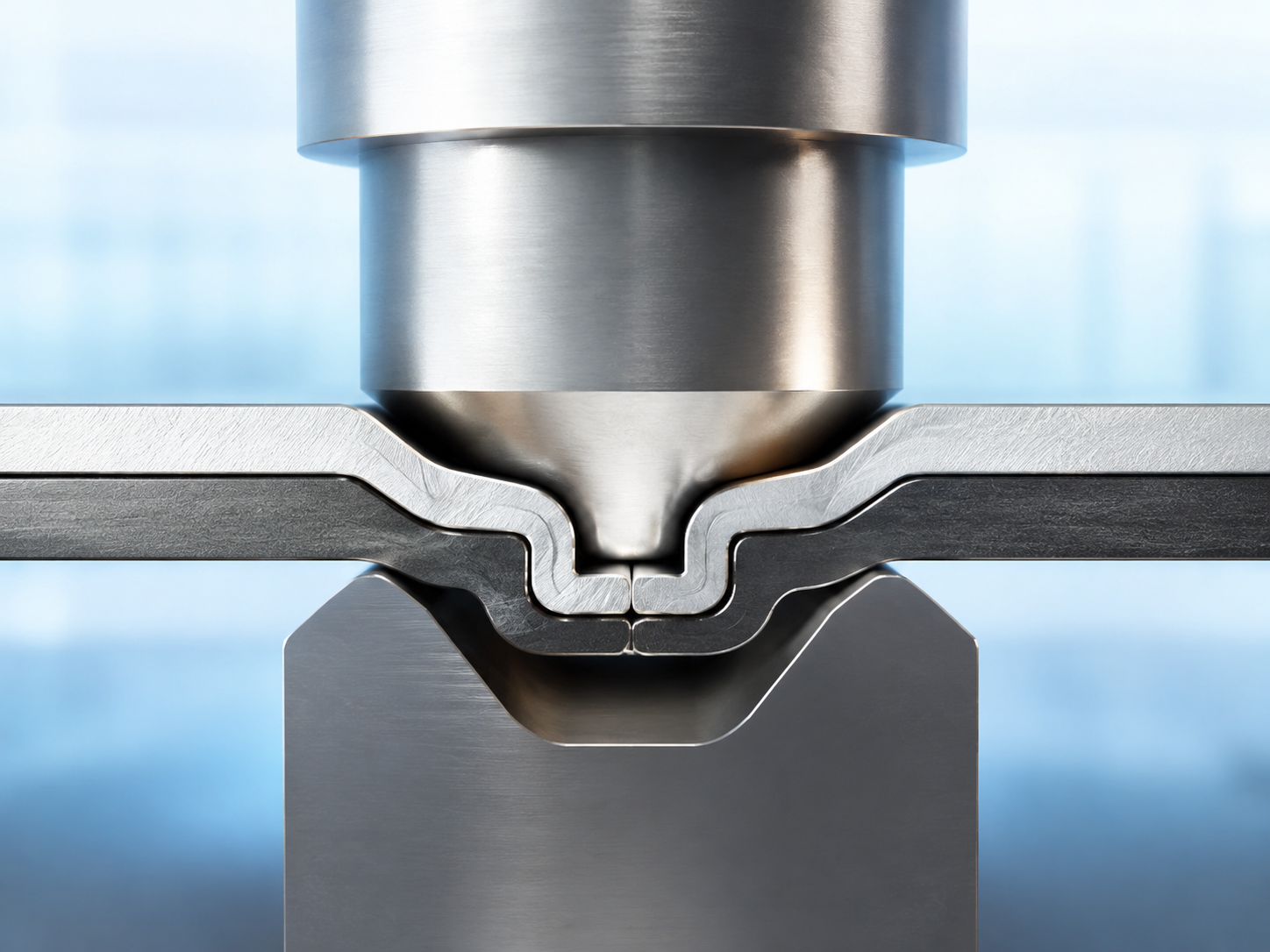
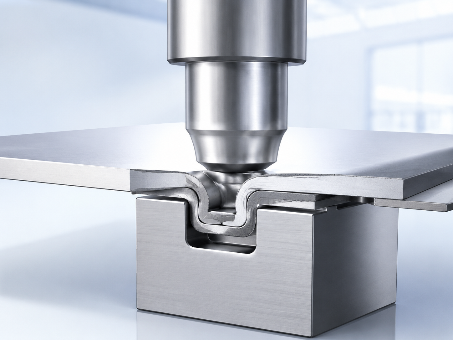
Punch-and-die mechanical joining deforms overlapping panels to create an interlock. This method adds no rivet and no welding heat at the joint, but it still requires two-sided tooling and a ductile material stack.

How the Clinch Joint Forms Without Rivets or Welding
  • Neck thickness near the punch-side transition
  • Undercut or interlock that resists button separation
  • Final bottom thickness after forming
  • Cracks, neck fracture and button-separation evidence

Joint geometry to examine

Joint-proof checkpoint

In practice, a visually acceptable button doesn’t guarantee the required load behavior. Failure risk remains because neck thickness and undercut must be tied to the load case before Simitch engineering releases a sample conclusion.

Request a Simitch engineering sample plan with section and load evidence.
Strength is a test result, not a shape claim

Strength is a test result, not a shape claim

An acceptable-looking surface button doesn’t guarantee the required load behavior. Neck thickness, undercut and bottom thickness can govern failure, as summarized in the clinching review hosted by PubMed Central.

Simitch engineering associates the concept of the punch-and-die with the material stack you’re working with. Include at least 2 evidence routes: section geometry and the approved load test. Verifiable results come from a test record, not a shape-based strength claim.
Added joining elements
0
Primary tool contacts
2: punch + die
Thermal joining stage at the point
0
Mandatory access assumption
2 tooling sides
Acceptance evidence
Section + load test
Added joining elements
1 rivet
Primary tool contacts
2: setter + reaction tool
Thermal joining stage at the point
0
Mandatory access assumption
Depends on rivet process
Acceptance evidence
Fastener/joint inspection + load test
Added joining elements
0
Primary tool contacts
2 electrodes
Thermal joining stage at the point
1
Mandatory access assumption
2 electrode sides
Acceptance evidence
Weld inspection + load test

0 added fasteners

Commercial evaluation must still include tool life, joint count, utilities, inspection, maintenance, sample work and quotation scope. A peer-reviewed joining-cost study supports this driver-based method, not a universal payback claim.

Match the Tool to Material Stack, Joint Location and Production Duty

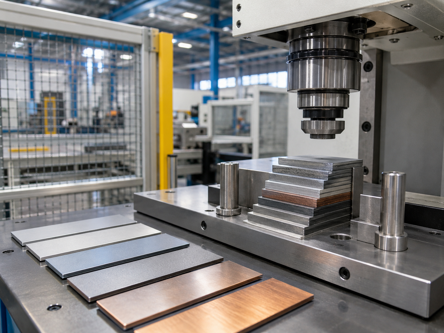
HVAC ducts, electrical boxes or appliance panels are an application category, not a joinability guarantee. A compact tool may be considered for a mild steel, stainless or other ductile stack, but the clinching process still requires material, access, load and production-control approval.

Tool to Material Stack 02
Tool to Material Stack 01
Tool to Material Stack 03
Production-fit checkpoint

A first sample doesn’t define long-term control when tooling, materials or surfaces drift. Future mismatch risk exists because 1 approved trial can’t represent every material heat, wear state or load direction, so Simitch engineers tie the application drawing to a revalidation plan.

Request a Simitch production-duty review with the drawing, material and shift inputs.

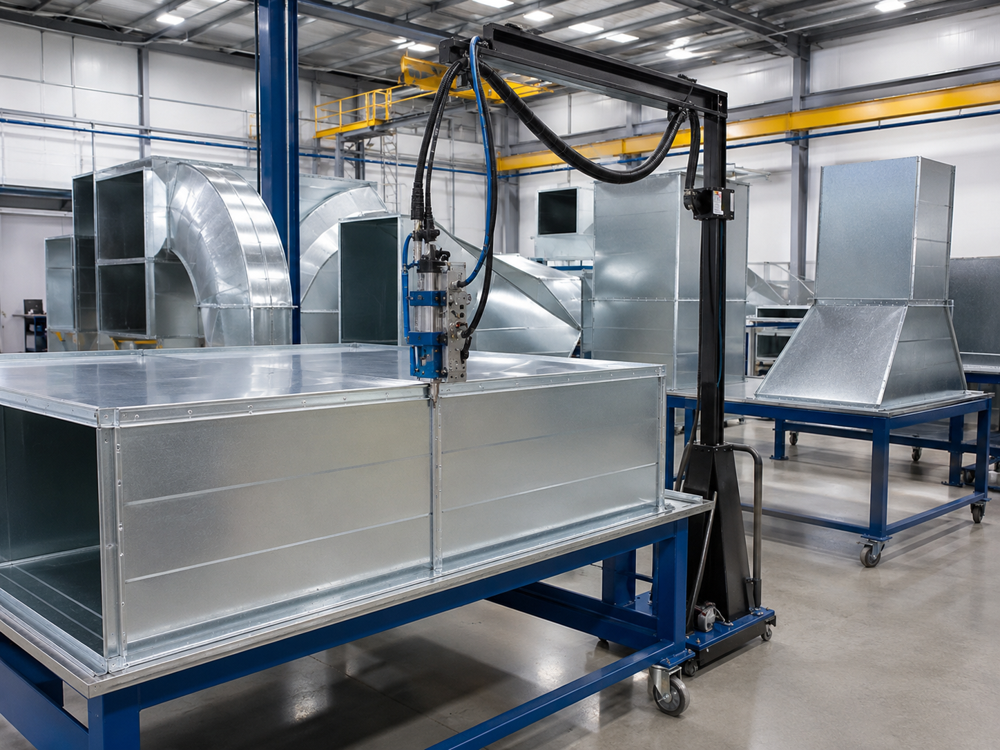
HVAC and duct fabrication

HVAC and duct fabrication

  • Record coating and individual gauge for every layer.
  • Mark folded edges, corners and internal obstructions.
  • Define joint spacing and the load or leak criterion.
  • Confirm handling around hoses, cables or suspension.
Cabinets and electrical enclosures

Cabinets and electrical enclosures

  • Show door returns, channels and hardware conflicts.
  • Identify the visible side and finish restrictions.
  • Specify peel, shear or stiffness expectations.
  • Send a representative corner or flange sample.
Panels, profiles and large assemblies

Panels, profiles and large assemblies

  • Measure required reach from the nearest open edge.
  • Describe how the part is supported during joining.
  • State shift duty and expected joints per part.
  • Determine if a portable tool or fixed station is the better fit.

Current literature also warns that higher-strength or less-ductile stacks don’t become acceptable just because the tool can reach them. An independent technical review treats material joinability, process parameters and tool design as interrelated variables.

  • Joints per part and parts per shift
  • Available pneumatic, hydraulic or electrical utility
  • Operator handling, suspension and reaction support
  • Tool change, inspection and spare-tooling plan
  • New material heat, grade or coating
  • Changed individual thickness or sheet order
  • Punch/die wear, replacement or eccentricity
  • Surface contamination or a changed load case
Match the Tool to Material Stack
Application evidence boundary

A first sample doesn’t define long-term control when tooling, materials or surfaces drift. That risk exists because 1 approved trial can’t represent every later material heat, wear state or load direction.

Simitch engineering can tie the suggested tool to the actual drawing and sample scope.

Portability and production duty are balanced before the quote is frozen.

These scenarios are still review pathways, not asserted Simitch customer results.

What to Send for a Sample Joint and Accurate Quotation

The honest version is simple: a comparable quote begins with 1 controlled technical package. Without it, 2 suppliers could price different frames, utilities, tooling, acceptance work and support while seeming to quote the same machine.

Sample Joint and Accurate Quotation

Quotation input package

  • Material grade, coating and surface condition
  • Individual sheet thickness and total stack
  • Punch-side and die-side sheet order
  • Front, side and joint-section drawings
  • Joint position, edge distance and obstructions
  • Joints per part, production rate and shift duty
  • Available air, hydraulic or electrical utility
  • Peel, tensile-shear or cross-tension requirement
  • Documentation language and destination market
  • Tooling, spares, training and support scope

Separate feasibility from approval

check if both tooling sides can reach and whether the stack is an appropriate candidate.

specify punch, die, approach, force source and handling assumptions without copying another supplier limits.

produce joints on typical material, including the projected coating and sheet order.

match section geometry, load results and failure mode to the customer’s acceptance criteria.

quote the machine, tooling, validation, spares, documents and support as 1 controlled scope.

ISO 12996:2013 specifies tensile-shear specimen geometry and a test method for a single mechanical joint on single or multilayer specimens up to 4.5 mm single-sheet thickness. Its fit for a Simitch project must be agreed against the customer’s material, joint type and acceptance plan.

Request a sample and quotation review with the same material, joint and scope inputs.

Request a quotation review

Simitch Engineering, Tooling and Production Control

Suzhou Simitch Machinery Co., Ltd. was established in 2006 and began with sheet-metal connection machinery. Supplied company history describes a move from introduced clinching technology to independent research and development, trademarks, technical patents and in-house production of key equipment and core parts.

Operator and point-of-operation review

Capability-proof checkpoint

Procurement risk begins with believing that nearly 20 years of company experience proves every configuration detail. Because every application is different, Simitch supplies drawing, sample and document proof for the quoted scope; unlike a borrowed specification, that evidence can be compared to the buyer’s criteria.

Request a Simitch capability and document review for the proposed machine.
“We do not select a portable frame from its outline alone. We start with the part drawing, material stack, tool approach and acceptance test, then decide what should be proved in a sample.”
— Simitch Engineering Team
01

Application review

02

Access shortlist

03

Tooling concept

04

Sample trial

05

Acceptance review

06

Production scope

Company history

Established in 2006

Technology path

Introduction to independent R&D

IP status

Trademarks and technical patents reported

Production scope

Key equipment and core parts reported in-house

Operator and point-of-operation review

Portable powered equipment still requires a configuration-specific safety assessment. OSHA 1910.212 requires guarding where an employee is exposed to injury at a point of operation; machine-specific safeguards vary by design and local rules.

Patents show why tool geometry needs controlled engineering review. US10328481B2 describes a dimensioned clinching-punch taper intended to influence joint strength; it isn’t evidence of Simitch dimensions.

Simitch Engineering, Tooling and Production Control
Documents available on request

Documents available on request

  • Obtain the most current product drawing and verified configuration information.
  • Ask for the sample record and agreed acceptance evidence.
  • Obtain, for your evaluation, actual quality and safety documentation provided with the offer.
  • Solicit tooling, spare parts, training and maintenance in a written scope for the project.

Need a document-led supplier review?

A mismatch can arise between requested proof and the documents supplied with a specific machine, because company history alone doesn’t establish configuration compliance. Simitch provides the current drawing, sample record and available documents for comparison with the buyer’s acceptance criteria.

Engineering Assessment Tools for Portable Clinching

Assess material compatibility, total thickness limits, and mechanical strength requirements to ensure optimal clinch forming integration.

Open Tool

Calculate required C-frame throat depth, punch stroke, and die-side accessibility against your specific 3D part geometries.

Open Tool

Evaluate clinching against spot welding and riveting based on cycle time, energy consumption, and long-term structural integrity.

Open Tool

Validate utility connections, tooling balances, safety controls, and material availability prior to scheduling equipment trials.

Open Tool

Frequently Asked Questions About Portable Clinching Tools

Verify drawing access, approach, opening, reach and interference with reference to part dimensions and surrounding structure. Both candidate machines may be feasible subject to material, sheet order, loading mode, joint condition and sample validation.


Simitch range currently isn’t represented within the available customer data. Send the full grade, thickness, coating, sheet arrangement and quantity for a tooling and sample-feasibility review.

Portable clinching may use various drive technologies, and the attached Simitch data doesn’t clearly demonstrate applicability for the two referenced systems. Define the available drive systems at each workstation for reference, and request revised configuration drawing documentation.

Only when the verified tool envelope clears the part and nearby structures.

  • Dimension the joint location, opening and required throat.
  • Show nearby folds, flanges, fasteners and fixtures.
  • Refer to the approved drawing to verify envelope of linkages – a photograph doesn’t establish the real space occupied.

Define required section measurements; tensile-shear or peel/cross-tension test, direction; sample quantity and acceptable failure modes prior to trial. Visual button inspection isn’t equivalent to validated destructive testing of the section and/or sample strength required for acceptance of a joint production process.

Components of the total offer, from machine features (frame, drive train, force capability, suspension, controls) through tooling, materials, sample processing, controls, documentation, service (spares, training) to logistics and warranty are variable. Specific prices/lead times from Simitch must be negotiated, not inferred from generic data.

Record the approved material, coating, thickness, sheet order, tooling, section measurements and load evidence. Revalidate after meaningful changes in tool wear, material, surface condition or load direction.

Reject the process if material ductility, access, load behavior, production controls, etc., can’t be approved.

  • Relocate the joint if access can’t be provided simultaneously for both tools; alternate approach; or use a joining technology where access can be provided simultaneously to both tool/anvil locations of the joint area.
  • Consider another joining method if the material arrangement forms an unstable interlock.