Get in touch with Suzhou Simitch Machinery Co., Ltd Company

Self-Piercing Riveting (SPR) Machines — Servo, Pneumatic-Hydraulic & Robotic Production Systems
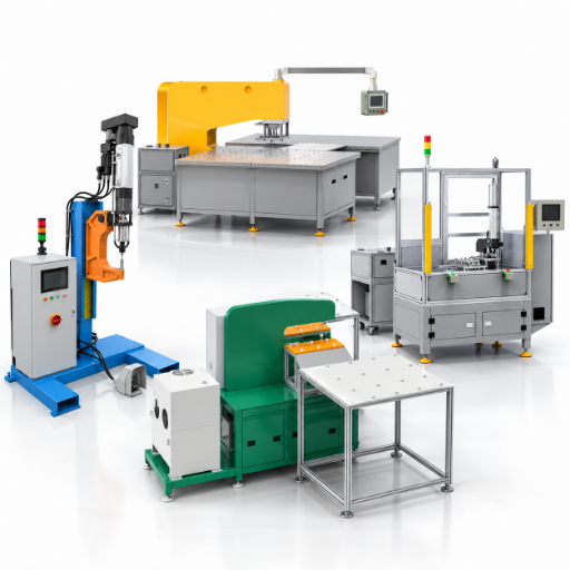
Choose self-piercing equipment based on your materials, joints, access and production—not on force alone. Simitch can provide hand-operated machines, CNC servo-driven systems and robotic automated riveting cells with the rivet, die, feed and control options your application needs.
2006
Simitch company establishment year
50 / 75 kN
Pneumatic-hydraulic punching-force options
5T / 8T
CNC servo thrust options
100 / 200 mm
Available servo stroke options
3 s
Nominal cycle in the supplied parameter sheets
Choose the Joint Before You Choose the Self-Piercing Riveting Machine
A successful SPR joint begins with a well-defined material stack: type of material, coating, arrangement of layers, thickness of each sheet, total thickness and performance requirements (static or fatigue). Then, punch and die action must provide the necessary rivet flare and interlock without causing cracks in the bottom sheet, buckling or damaging the rivet head.
Ensure that your assembly offers accessibility on both sides of the joining process – die side and punch side.
Employ a ductile material on the bottom, and test the expected layering arrangement.
Decide how any added components—sealants, coatings, gaps and adhesives—may influence the joining operation.
Establish objective test and inspection criteria; the joint should be assessed for head condition, joint cross section and joint-load results.
Why a force rating cannot be the whole specification
A peer-reviewed overview of SPR failures and optimization shows why a force rating alone cannot prove that a rivet, die and material stack will form an acceptable interlock. Rivet hardness, leg length, die design, metal strength and ductility, and the coating also affect the load-elongation characteristics and final joint cross-section.
Engineering note
Use head perpendicularity primarily as a tool to monitor process variability, not as the sole determinant of successful or failed joints. During joint development, section the assembly to check for rivet bloom, interlock formation, minimum bottom-sheet thickness, cracks, head engagement and gaps between sheets.
A machine can reach the target force and still fail if the lower sheet lacks ductility or the die side is inaccessible. Therefore, Simitch will typically request your part or a complete material-stack description before recommending a self-piercing system.
+
Define
List every layer, coating, thickness and joining requirement.
+
Trial
Choose a starting rivet, die and force window for sample joints.
+
Validate
Inspect head condition, cross-section geometry and mechanical load.
+
Release
Freeze the tool set, recipe, monitoring window and inspection plan.
Where SPR fits—and where it does not
This cold joining process is suitable for aluminum, steel and some dissimilar materials without pre-drilled holes or thermal welding. It can create clean surfaces for structural sheet assemblies and OEM production lines.
| Fit question | Positive signal | Boundary that needs a test |
|---|---|---|
| Material stack | Ductile die-side layer with a controlled total thickness | Brittle composites, very high-strength sheet or an unfavorable layer order |
| Part access | Clear punch-side and die-side access around the joint | Closed geometry that prevents die support |
| Production intent | Repeatable joints from manual, suspended, fixture or robotic equipment | Frequent unplanned stack changes without recipe and tool control |
| Quality plan | Sample cross-sections, load testing and monitored production | Approval based only on rivet-head appearance |
Confirm the joint before locking the machine
A proven application window, validated with your samples, is more useful than a larger force rating alone. Request a detailed assessment of your drawings and sample materials from the Simitch engineering team.
Compare Pneumatic-Hydraulic, Servo and Automated Riveting Systems
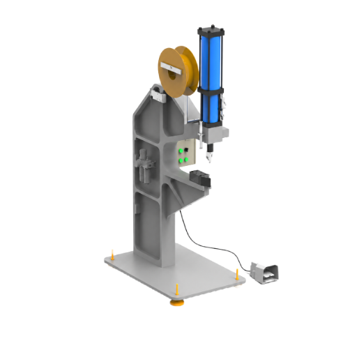
Compact Pneumatic-Hydraulic SPR System
- Main power pneumatic or hydraulic
- Maximum punching force 50 kN or 75 kN
- Nominal cycle 3 seconds
- Control handle or foot switch
- Rivet feed automatic feed bowl or manual feed
- Mounting bracket, suspension or 360-degree suspension
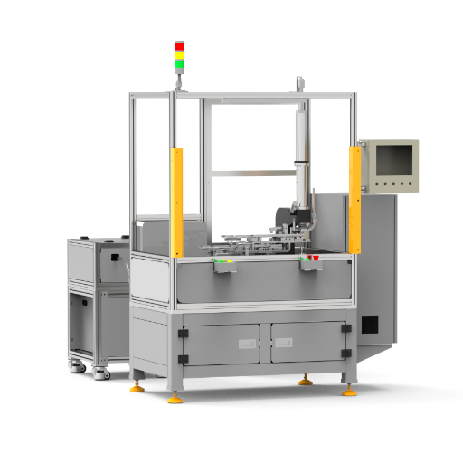
CNC Servo-Driven SPR System
- Main power CNC servo drive
- Thrust 5T or 8T
- Stroke 100 mm or 200 mm
- Nominal cycle 3 seconds
- Control HMI with user-permission modes
- Mounting bracket, suspension, 360-degree suspension or robot
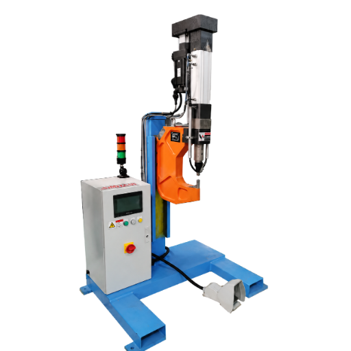
Automated Flexible SPR Station
- Architecture modular automated station
- Integration fixture, material handling or industrial robot
- Process data storage for defect analysis and process improvement
- Quality method joining-force evaluation with application-set pressure
- Production use repeatable multi-point or multi-part assembly
- Configuration engineered to the part and line interface
A practical machine-selection matrix
Automation is not necessarily the lowest-cost alternative. A hand-operated or suspended riveter might be a more appropriate solution for pre-production models, prototypes, reparable fixtures, or varied part numbers, whereas automated, servo-driven riveting machines excel when standardized production and precise data logging are required.
| Decision factor | Pneumatic-hydraulic | CNC servo-driven | Automated flexible station |
|---|---|---|---|
| Available force or thrust | 50 / 75 kN | 5T / 8T | Selected around the installed setting unit |
| Available stroke | Defined by the selected unit and tooling | 100 / 200 mm | Defined by setting unit, fixture and robot path |
| Operator interaction | Handle or foot switch | HMI and permission-controlled modes | Line HMI, interlocks and automatic sequence |
| Rivet feeding | Manual or automatic feed bowl | Configured manual or automatic feeding | Rivet feeding system matched to line demand |
| Quality data | Inspection plan defined around the application | Online quality monitoring and data storage available | Process traceability and result storage planned at cell level |
| Typical fit | Flexible manual work, suspended tooling and moderate-volume assembly | Recipe-based production and force-displacement monitoring | Mass production, robotic cells and integrated fixtures |
Ask Simitch for a joint trial and an equipment recommendation before committing to a 50 kN, 75 kN, 5T or 8T configuration.
Request Joint TrialBuild Repeatability Into the Riveting Process
Quality comes from control over the total joining system: part location, fixture position, clamp state, rivet attitude, tooling approach and material stack. A PLC may manage the signals but can’t fix a bad joint design. Peer-reviewed SPR process literature likewise treats joint geometry and process response as application-specific evidence.
- Lock recipe to the part and rivet/die combination once acceptable.
- Verify rivet presence, feed-system readiness, fixture state and safe-zone status before the setting cycle begins.
- Timestamp the recorded results tied to machine identifiers, part data and process lines to aid traceability.
- Establish acceptable parameters for a normal production release including appropriate methods for error handling, recovery rules, and permitted operators.
The honest version: process monitoring improves control only after the joint has been physically validated. It does not turn an untested rivet-and-die choice into a qualified joint.
Force-displacement monitoring should answer a specific question
For servo-machine applications, force and position data from a successful trial can establish an expected joining-process signature. Use data from validated samples to monitor process drift—don’t simply transfer limits from another application.
Quality-monitoring sequence
- Produce additional joints across the established range of material and process variation.
- Cross-section representative joints and run the agreed mechanical test.
- Correlate accepted samples with a reference on the force/displacement curve, the status of the head, and other relevant data.
- Use those limits to define warning and reject points, then confirm them during a controlled production run.
A flush-looking rivet head is not necessarily proof of a sound subsurface interlock. Visual head appearance is useful for process drift, but it cannot replace cross-section and load testing during joint development.
Robot integration, end-of-arm tooling and line ownership
Use a six-axis robot to place the setting tool on an assembled structure, or use a stationary C-frame accessed by a robot that presents the part. Other factors include tool weight, robot reach, umbilical routing, accessibility, fixture datums and available cycle time.
| Integration item | Question to close before design release | Evidence at acceptance |
|---|---|---|
| Robot and end effector | Who owns reach, payload, collision and service-position checks? | Approved simulation, access review and dry-cycle record |
| Control system | Which controller owns recipes, safety handshake, alarms and reset logic? | Interface list, sequence chart and fault-recovery test |
| Automatic feeding | What is the permitted refill interval, jam response and low-level warning? | Run-off under representative rivet consumption |
| Data logging | Which fields, identifiers, retention time and export format are required? | Sample production record and retrieval test |
| Maintenance | Which wear parts are stocked, and how is a changed tool requalified? | Spare-parts list, maintenance plan and restart checklist |
Look for descriptive terms such as “closed-loop control,” “predictive maintenance,” “digital twin” or “overall equipment effectiveness,” but don’t assume those functions are included because the machine has an HMI. Clarify each function, its data source, the data owner and the performance-verification method before issuing the request for quotation.
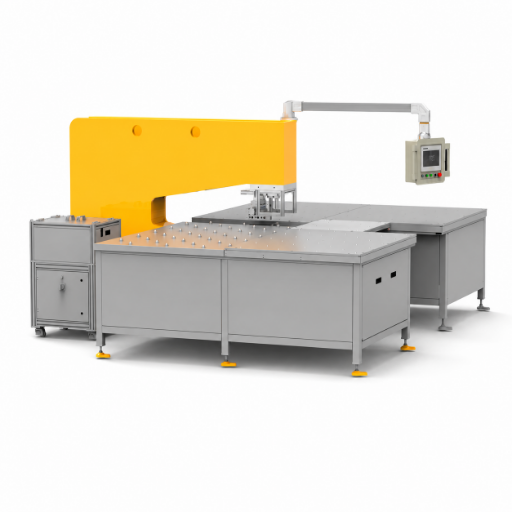
Release the Joint With Evidence, Not Appearance Alone
Final joint verification connects the functional design to actual part performance. Depending on the end-use conditions, tensile-shear, peel, fatigue, corrosion or leak testing may apply to automotive assemblies, household appliances, signposts, rail components and aerospace substructures.
- Rivet presence and feed confirmation
- Head contact or flushness trend
- Force and displacement response
- Recipe, tool and part-number match
- Visual cracks, gaps or surface damage
- Cross-section geometry and interlock
- Rivet-leg spread and buckling
- Remaining bottom material
- Joint-specific mechanical load
- Failure mode and consistency across samples
Peer-reviewed SPR literature addresses head form, interlock shape, observed cracks and the force-displacement signature, but it does not provide one universal set of values for every material system. Acceptable joint parameters are finalized after testing the specific aluminum alloys, steels, adhesives, coatings and rivet materials in the proposed joint.
Provide material designations or certificates, description of layer configuration and thickness of each material element, details on coatings, drawing information regarding joint geometry, the envelope of the available C-frame, and specification of the required load or customer standard. Include sufficient samples to determine process parameters, perform cross sections, and perform mechanical tests if the physical system is available.
More force is not always the right choice. Excessive force may increase deformation or mask a misaligned die and rivet, while insufficient force may leave the setting stroke incomplete; the correct force is the one proven by a validated joint.
| Observed condition | Possible process question | Next check |
|---|---|---|
| Raised or inconsistent head | Did stack thickness, rivet length, die support or stroke change? | Compare trend data and cross-section samples |
| Cracked die-side material | Is the lower layer sufficiently ductile and correctly ordered? | Review stack order, rivet geometry and die profile |
| Weak or variable joint load | Is interlock formation stable across tolerance limits? | Correlate load results with geometry and force-displacement curves |
| Feed interruption | Are rivet presentation, hose routing or bowl settings unstable? | Run an extended feed test at representative consumption |
Match the SPR Equipment to the Part, Volume and Factory Flow
SPR is used in cars, buildings, appliances, road signs and general sheet metal. An open-access engineering study also evaluates polymer-metal hybrid structures. Given this diversity, a single machine or tool set cannot do everything.
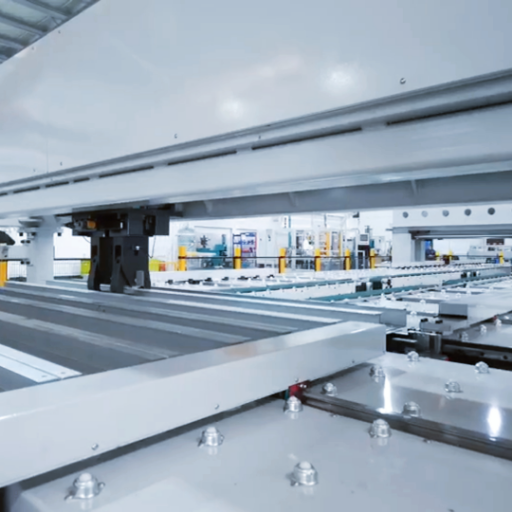
[ SYSTEM CONFIGURATION / PROCESS DATA ]
Detailed application parameters and equipment configuration for this specific structural requirement.
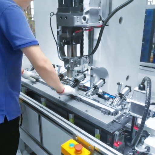
[ SYSTEM CONFIGURATION / PROCESS DATA ]
Detailed application parameters and equipment configuration for this specific structural requirement.
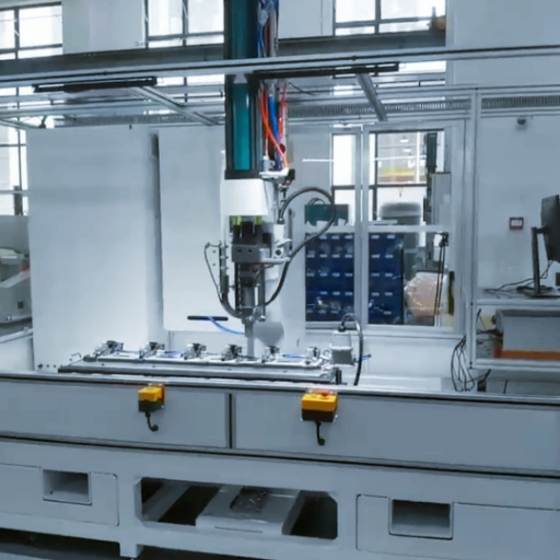
[ SYSTEM CONFIGURATION / PROCESS DATA ]
Detailed application parameters and equipment configuration for this specific structural requirement.
Plan Machine Guarding, CE Records and Handover by Configuration
Regulation (EU) 2023/1230 sets health and safety requirements for machinery placed on the European market, including technical documentation, conformity assessment, an EU declaration of conformity, CE marking and instructions. The applicable obligations depend on the scope, supply date, destination market and project responsibilities, so confirm them for the final configuration.
Risk assessment
Hazards, limits, intended use and foreseeable misuse
Technical file
Configuration drawings, calculations and supporting evidence
Conformity route
Applicable requirements, assessment and declaration
Instructions
Installation, operation, maintenance and residual risks

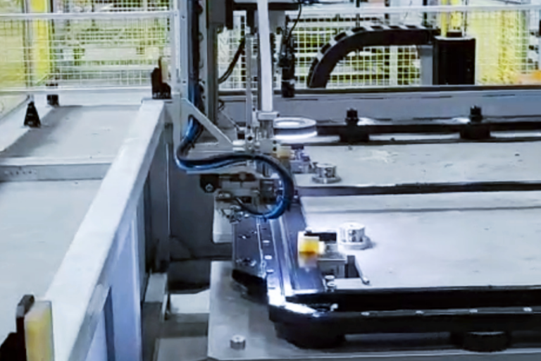
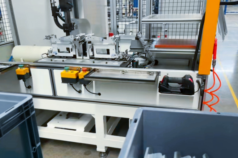
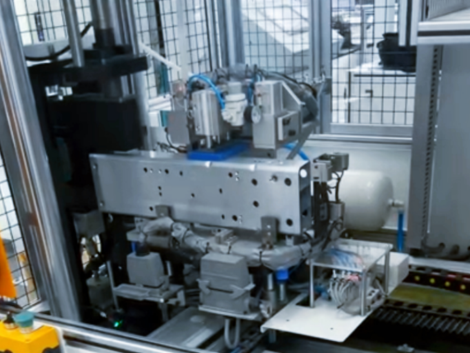
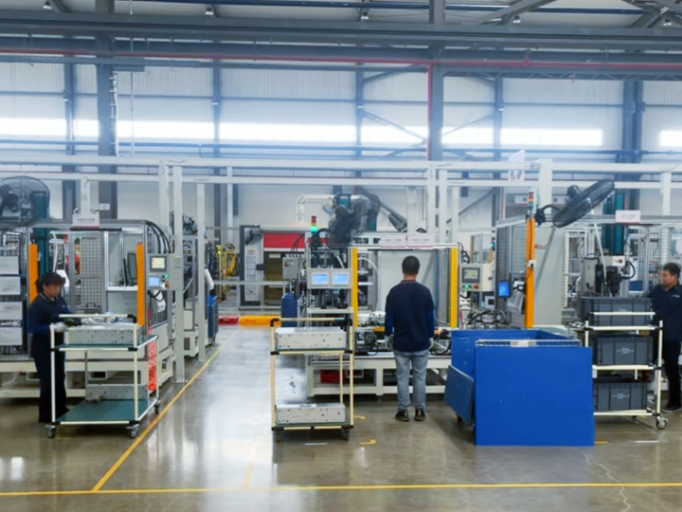
Point-of-operation safety must be designed around the cycle
OSHA 1910.212 requires guarding where machine operation exposes an employee to injury, including the point of operation. Depending on the layout, suitable measures may include fixed or interlocked guards, two-hand controls, electronic protective devices, safe fixtures and controlled operating modes.
- Define loading, setup, teaching, maintenance and jam-recovery modes separately.
- Prevent access to the punch-and-die danger zone during the operating cycle.
- Document how the introduction of a suspended tool, a foot switch, robot cell, and/or a fixture affects the risk.
- Verify each safety function within the finalised machine or production line.
A CE logo in a brochure does not replace a configuration-specific technical file, a risk assessment and the declaration of conformity. The same also applies to a general patent declaration by a supplier, which should be audited by asking for the specific public identifier(s) if intellectual property evidence contributes to the qualification.
Technical-file request
In the request for quotation, specify the destination country, system language, interface scope and required standard. Request a document index before final order placement so responsibility for the setting unit, robot, fixture, feed system and completed cell is clear.
Confirm the configuration boundary
The plain truth is that a safety file for a 50 kN manual tool doesn’t magically become the safety file for a 75 kN system on a robotic production line.
Ask for a bespoke Simitch compliance document review and a responsibility matrix for the risk assessment.Frequently Asked Questions About SPR Machines
What information is needed to select a self-piercing riveting machine?
Provide every material layer and thickness, layer order, coatings or adhesive, joint drawing, target load, accessible tool envelope, joints per shift and required quality record. Add the planned operating method, destination market, part-change pattern and any customer standard that will govern acceptance. A physical sample is preferred when the material stack is new or difficult because its cross-section and load result anchor the tool and parameter choice.
Can one SPR machine join both aluminum and steel?
Sometimes, but each stack needs its own validated rivet, die and process window.
How do I choose between 50 kN, 75 kN, 5T and 8T configurations?
Do not convert the labels into a recommendation without a joint trial. Simitch selects a starting version from the material stack, access envelope and tool geometry. Cross-sections and the required mechanical test then show whether the setting produces acceptable interlock, head condition and failure behavior across the expected material tolerance.
Is a servo-driven riveting system always better?
No. Servo equipment earns its place when data or recipe control is required; flexible manual work may favor a simpler pneumatic-hydraulic system.
Does self-pierce riveting need access to both sides of the part?
Normally, yes: the punch acts from one side and a die supports and forms the joint from the other. Send the part geometry early so throat depth, C-frame clearance and collision risks can be checked.
Can head flushness prove that an SPR joint is good?
Head condition is a useful non-destructive process indicator, but it does not expose the subsurface interlock or every crack and layer gap. Cross-section and load testing are used during joint development to establish the approved process window.
What cycle time should I use for production planning?
Supplied parameter sheets list a nominal 3-second machine cycle for the shown pneumatic-hydraulic and servo versions. Actual line throughput must also include part handling, robot travel, clamping, rivet feeding, inspection, changeover and fault recovery.
Can Simitch integrate the equipment with a robot?
The supplied servo configuration lists robot mounting, and the automated station material describes robot integration and production-data storage. Final responsibility for the robot, fixture, safety, controls and completed cell should be defined in the project interface list.
What should a factory acceptance test cover?
Cover qualified sample joints, cycle sequence, tooling, feed stability, recipe control, alarms, safety functions, data records, recovery steps and an agreed production run. The protocol should state the sample size, acceptance criteria and owner of each corrective action.
How is SPR machine pricing determined?
Pricing changes with the setting unit, force and stroke, C-frame or suspended tooling, rivet feed, monitoring, fixture, robot interface, guarding, technical records and service package. A complete request for quotation lets suppliers separate standard equipment from application-specific engineering.